EP0484720B1 - Dispositif d'injection d'air préchauffé dans un four à cuve et procédé de fabrication de rotules convexes d'articulations sphériques - Google Patents
Dispositif d'injection d'air préchauffé dans un four à cuve et procédé de fabrication de rotules convexes d'articulations sphériques Download PDFInfo
- Publication number
- EP0484720B1 EP0484720B1 EP91117866A EP91117866A EP0484720B1 EP 0484720 B1 EP0484720 B1 EP 0484720B1 EP 91117866 A EP91117866 A EP 91117866A EP 91117866 A EP91117866 A EP 91117866A EP 0484720 B1 EP0484720 B1 EP 0484720B1
- Authority
- EP
- European Patent Office
- Prior art keywords
- ball
- refractory
- pipe
- joint
- shielding
- Prior art date
- Legal status (The legal status is an assumption and is not a legal conclusion. Google has not performed a legal analysis and makes no representation as to the accuracy of the status listed.)
- Expired - Lifetime
Links
- 238000000034 method Methods 0.000 title claims description 6
- 229910000831 Steel Inorganic materials 0.000 claims abstract description 22
- 239000010959 steel Substances 0.000 claims abstract description 22
- 230000001681 protective effect Effects 0.000 claims abstract description 3
- 238000004519 manufacturing process Methods 0.000 claims description 31
- 238000005266 casting Methods 0.000 claims description 11
- 239000011819 refractory material Substances 0.000 claims description 10
- 210000002105 tongue Anatomy 0.000 claims description 9
- 230000002093 peripheral effect Effects 0.000 claims description 4
- 210000004417 patella Anatomy 0.000 description 7
- 229920002994 synthetic fiber Polymers 0.000 description 7
- 239000002184 metal Substances 0.000 description 6
- 239000000919 ceramic Substances 0.000 description 5
- 239000000835 fiber Substances 0.000 description 5
- 230000000295 complement effect Effects 0.000 description 4
- 238000007789 sealing Methods 0.000 description 4
- 238000003466 welding Methods 0.000 description 4
- 230000015572 biosynthetic process Effects 0.000 description 2
- 238000006073 displacement reaction Methods 0.000 description 2
- 238000009413 insulation Methods 0.000 description 2
- 230000002427 irreversible effect Effects 0.000 description 2
- 230000004087 circulation Effects 0.000 description 1
- 230000002860 competitive effect Effects 0.000 description 1
- 238000005520 cutting process Methods 0.000 description 1
- 239000003292 glue Substances 0.000 description 1
- 238000009434 installation Methods 0.000 description 1
- 238000012423 maintenance Methods 0.000 description 1
- 239000000463 material Substances 0.000 description 1
- 230000007935 neutral effect Effects 0.000 description 1
- 230000000149 penetrating effect Effects 0.000 description 1
- 230000035515 penetration Effects 0.000 description 1
- 230000000717 retained effect Effects 0.000 description 1
- 230000006641 stabilisation Effects 0.000 description 1
- 238000011105 stabilization Methods 0.000 description 1
- 239000002023 wood Substances 0.000 description 1
Images





Classifications
-
- C—CHEMISTRY; METALLURGY
- C21—METALLURGY OF IRON
- C21B—MANUFACTURE OF IRON OR STEEL
- C21B7/00—Blast furnaces
- C21B7/16—Tuyéres
- C21B7/163—Blowpipe assembly
Definitions
- the present invention relates to a device for injecting preheated air into a shaft furnace, consisting of several distinct cylindrical elements or segments consisting of an outer steel shield and an inner refractory lining and comprising at least one connected central tubular element, on one side, by a first spherical articulation and first compensator to an upper tube secured to a circular duct for supplying preheated air surrounding the furnace and, on the opposite side, by a second spherical articulation and a second compensator to a tube lower which is extended by an elbow and a nozzle, the latter being articulated on a nozzle fixed in the wall of the furnace and in which device the spherical joints comprise a convex ball formed by the end of one of the segments and able to pivot in a concave base formed by the end of the adjacent segment and a refracting joint soft interposed area.
- wind carrier is exposed to mobility and sealing problems. Indeed, due to the high temperature of the preheated air (temperature of the order of 1200 ° C. or more) and the high temperature prevailing inside the oven, the wall of the latter, as well as the pipe circular and the blower are exposed to thermal expansion and deformation causing significant relative displacements between the circular pipe and the wall of the oven. It is therefore necessary that the wind carrier is able to compensate for these relative displacements while avoiding leaks of gas or preheated air.
- US Patent No. 3,766,868 provides a wind carrier of the kind described in the preamble.
- This wind carrier was subsequently perfected by the design of a universal joint with a spherical joint of the kind described in document DE-C2-2218331.
- the three articulations of this wind carrier allow the compensation of all the relative movements between the circular duct and the wall of the furnace.
- the tightness at the joints is ensured by bellows compensators, while the mechanical stability is ensured by associated cardanic connections, at the two universal joints, at the two opposite ends of the central tubular element.
- the object of the present invention is to provide a new device of the kind described in the preamble, which has better resistance to wear at the joints, which, by its numerous variants, adapts perfectly to the requirements of the user. , which offers more ease of manufacture and replacement, while allowing a reasonable manufacturing price.
- the device proposed by the present invention is essentially characterized in that the radius of curvature of each spherical joint is of the order of magnitude of half the diameter of the various cylindrical elements and in that the convex ball joints of the spherical joints include a protective sheath made of refractory steel and which extends to the diametrical base of the ball joint.
- the reduction in the radius of curvature of the spherical joints allows better guidance of the ball joints in their base while reducing the risk of impact and wear of the soft joints and allowing to always keep the same width of the joint.
- the present invention also proposes a new method of manufacturing a convex ball joint of a spherical joint of a device for injecting preheated air into a shaft furnace, consisting in first making the ball joint sheath in refractory steel and providing this of an interior refractory lining, characterized in that the end of a refractory steel tube is deformed until it has the shape of a convex dome with a central opening and a surface convex spherical extending between the central opening and the cylindrical surface of the tube in that the sheath thus formed is placed on a support, in that there is axially inside a cylinder with a slightly diameter smaller than the diameter of said central opening and in that refractory material is poured between the cylinder and said sheath
- the ball joints are formed by the lower ends of the upper tube and of the central tubular element.
- the ball of the central tubular element can either form an integral part of this element, or be separated from it by a transverse cut filled by an annular seal.
- the shield of the central tubular element and that of the lower tubing can be connected directly to each other through a compensator, or by means of a flange or a detachable weld.
- the base of the lower joint can be formed in the refractory lining cast in a cylindrical sheath of refractory steel arranged coaxially inside the shielding of the lower pipe.
- the refractory soft seal can be partially attached to the shield and partially to the edge of the plate. It can also be partially attached in an interior housing of the cylindrical sheath and partially on the refractory. According to a variant, it can also be partially attached to the refractory and partially in a housing delimited by the upper part of the sheath and by a ring welded inside the shielding.
- the plates of the two spherical joints are provided respectively at the two opposite ends of the central tubular element, while the convex ball joints are provided on the upper tube and the lower tube.
- the known blower portrayed in FIG. 1 by the reference 20 connects a main circular pipe 22, arranged around a blast furnace, to the wall 24 thereof.
- This blower has a rectilinear oblique section consisting of a central tubular element 26 articulated at its upper end on a tube 28 fixed on a connector of the circular pipe 22 and, by its lower end on a tube 30 which is clamped on a elbow 32.
- This elbow 32 is extended by a nozzle 34 whose end is articulated on a nozzle 36 fixed in the wall 24 of the oven.
- the upper 38 and lower 40 joints between the central tubular element 26 and the two pipes 28 and 30 are universal joints allowing relative movements between the circular pipe 22 and the wall of the furnace 24.
- Each of the two joints 38, 40 is constituted by a convex part subsequently called a ball joint and by a concave part subsequently called a plate.
- the ball joint forms part of the upper tubing 28 and enters the plate formed by the upper end of the central element 26.
- the lower part of this forms the ball joint of the joint 40 and enters the plate formed by the upper part of the lower tube 40.
- the ball joint of the joint 40 is an integral part of the central element 26, that is to say that its refractory lining extends, without interruption, from the upper end to the tip of the patella.
- This constitution of the central element 26 facilitates its manufacture in comparison with the variant illustrated in FIG. 1a in which the ball joint is separated from the rest of the central element and is attached to the latter at the level of the flange provided for fixing. gimbal 50a.
- This variant illustrated in FIG. 1a has, on the other hand, the advantage of allowing separate disassembly of the lower part constituted by the tube 30 and the joint 40a or the upper part constituted by the rest of the central element 26 and l 'upper articulation 38 with the tubing 28.
- the upper articulation 38 must necessarily be constituted in accordance with FIG. 1a in order to be able to detach the wind carrier from the circular pipe 22.
- FIG. 2 illustrates a known embodiment of an articulation as proposed in document DE-C2-2218331.
- This embodiment is essentially distinguished from that of FIG. 1 by the fact that the articulations are spherical as shown by the joint between the ball joint 58 and the base of the tube 30.
- the ball joint 58 is also separated from the central element 26 like FIG. 1a.
- the embodiment according to Figure 1 remains however also possible.
- a first sealing ring 62 for example, made of ceramic fibers is incorporated into the refractory of the plate 60 and closes the passage between the plate 60 and the tip of the ball joint 58.
- Another seal also made of ceramic fibers is disposed in the annular space between the lower end of the metal sheath 68 of the ball joint 58 and the cylindrical connection of the compensator 44. This seal 64 is wedged between the edge of the plate 60 and a peripheral ring 66 welded to the sheath 68.
- seals 62 and 64 are essentially to prevent or reduce the penetration of hot air inside the compensators 44 in order to better protect them from high temperatures.
- the lower edge of the sheath 68 can come to crush the seal 64 on one side, while on the opposite side, the ring 66 tends to compress the seal 64 in the axial direction. Since these refractory joints lack elasticity, they risk undergoing by these movements an irreversible deformation, which reduces their effectiveness.
- This device according to FIG. 2 has another handicap, insofar as the sheath 68 of refractory steel extends only up to the limit of the cylindrical part of the ball joint 58.
- the refractory point of the ball joint 58 is, of this fact, quickly invaded by micro-cracks which are at the origin of a rapid wear and a rupture of the point of the patella.
- the absence of support for the refractory of the tip of the ball joint 58 also requires a relatively large radius of curvature R to prevent this convex tip not supported by the sheath 68 from being too tapered. This, in turn, is at the origin of the cutting edge between the cylindrical part and the convex part of the sheath 58 and which risks crushing the seal 64 during the angular movements of the ball joint.
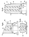
- FIGS. 3 and 3a each show half of a joint in accordance with the present invention, the figures being brought together so as to show an entire joint, the left part of which represents the version with ball joint separated from the central segment and whose Right version is the one whose kneecap is part of the central segment.
- Figures 3 and 3a show that the ball proposed by the present invention 70, 70a is completely enveloped by its refractory steel sheath 72, 72a which extends to the base of the ball around its convex section.
- the manufacture of such a refractory sheath 72, 72a in one piece with a convex section is made possible by a clever manufacturing process explained in more detail below.
- the ball joint proposed by the present invention has a smaller radius of curvature, of the order of magnitude of half the diameter of the segments of the wind carrier, which improves its mobility.
- a joint 74 for example made of ceramic fibers, is provided between the ball joint 70, 70a and the refractory of the tubing 76.
- This joint can, for example, be bonded to the shielding of the tubing 76 between two retaining rings 78, 80
- the joint 74 perfectly matches the shape of the point of the ball joint and extends over the major part of the convex section thereof. If the wind carrier is designed to accommodate a maximum axial misalignment of 7 °, the ball joint 72, 71, can deviate by 3.5 ° on either side from its neutral position in the figures, which is illustrated in the angles ⁇ and ⁇ . During such extreme pivoting, the seal 74 always forms a thick sealing cushion without being compressed by the ball joint 70, 71, owing to the fact that the width of the slot remains constant during the relative pivotings.
- a cylindrical tube 82 made of refractory steel is used, possibly provided with a small peripheral flange 84 if it is the embodiment of FIG. 3.
- a small peripheral flange 84 On the side opposite to the flange 84, it is practiced on all around, at regular intervals, cuts according the generator, of a depth corresponding to the length of the convex section of the patella to be produced.
- These cutouts 86 thus define tongues 88 identical to each other.
- tongues 88 are then folded down towards the axis of the tube 82 until the cutouts 86 are completely closed to define a spherical dome having a central opening 90 formed by the front facets 92 juxtaposed with the tongues 88.
- This folding of the tongues 88 can be carried out in a mold with a spherical bottom.
- the sheath 72 is then finished by welding the different tabs 88 to one another over the entire length of the cuts.
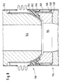
- FIG. 5 illustrates a first embodiment of the oblique section of a wind carrier with two spherical articulations 94 and 96 identical to each other and each comprising a ball joint wrapped in a refractory steel sheath produced according to the method described with reference to FIG. 4.
- the means for mechanical stabilization of the joints 94 and 96 have not been shown.
- These means although present in practice, may be means known per se, such as cardan joints or tie rods in accordance with document EP-A1-0363576.
- FIG. 5a illustrates the variant already described above, according to which the ball joint of the lower articulation 96a is separated from the central tubular element 98a.
- the sealed connection between the central element 98 and the lower tube 100 is produced by means of a flange 102 at the upper end of the sheath of the ball joint.
- the central element 98 also includes an upper flange 104 beyond the compensator of the upper articulation 94 to be fixed to the connector of the circular pipe not shown.
- these flanges 102 and 104 are moreover necessary in order to be able to manufacture the three elements separately, namely the central element 98, the lower tube 100 and the upper tube 106 which is simply constituted by the ball joint of the ball joint 94. This fabrication will now be illustrated with reference to FIGS. 6a, 6b and 6c.
- FIG. 6a illustrates the manufacture of the refractory of the ball joint 106.
- the sheath 72 produced according to the method described with reference to FIG. 4 is turned over on a support 108, for example made of wood, the central opening 90, of preferably down.
- a cylindrical shape 110 for example made of expanded synthetic material, is introduced into the sheath 72 and it is ensured that it is held in place, for example by means of a plug 112 fixed in the support 108 and penetrating into an axial channel of the form 110. It therefore only remains to pour the refractory material 114 into the annular space delimited by the form 110 and the sheath 72 by using the latter as a mold.
- FIG. 6b illustrates the manufacture of the central element 98.
- the assembly formed by the shield 116 of the central element with the sheath of the lower ball joint and the upper compensator is turned over, the flange 104 downwards.
- the ring 120 delimiting the housing of the joint of the upper articulation 94 closing the opening around the support.
- the upper profile of the support 118 is complementary to the shape of the base of the articulation 94.
- Figure 6c illustrates the manufacture of the lower tubing.
- the shield 126 of this tube including the compensator of the lower joint is turned upside down, upper flange, on a support 128 identical to the support 118 used previously.
- a form of expanded synthetic material 130 whose external shape corresponds to the inner channel of the tubing 100 finished and the space around the shape 130 is filled with refractory material.
- the three forms of synthetic material 110, 122 and 130 can remain in place for the purpose of mounting the blower, since they will be consumed automatically when the blower is put into service.
- FIG. 7 shows a second embodiment of a wind carrier with a central element 132, a lower tube 134 and a ball joint 136.
- the shielding of the central element 132 is connected through the compensator of the lower articulation to the shielding of the pipe 134.
- the flange 102 of the embodiment of FIG. 5 has therefore disappeared, which makes it possible to reduce the manufacturing price of the wind carrier .
- the manufacturing step illustrated in Figure 6c is no longer possible and it is necessary to provide other devices in order to be able to pour the plate of the lower joint.
- the refractory of the tubing 134 is poured in two successive operations, which is symbolized by the interruption 138.
- This also has repercussions on the design of the lower articulation, in particular of the 'trim of the tubing 134 and Figures 8 and 9 illustrate several embodiments.
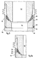
- FIG. 8 shows the details of the spherical joint 140 between the central element 132 and the lower tube 134.
- the ball joint 142 is identical to the previous embodiment, that is to say with a refractory sheath produced according to the figure 4.
- the base 144 of the joint 140 formed by the upper part of the refractory lining of the tubing 134 is modified.
- the refractory lining forming the plate 144 is poured inside a cylindrical sheath 146 made of refractory steel and arranged coaxially inside the metal shielding of the pipe 134.
- the sheath 146 can be held in place by means of two rings 148 and 150 fixed respectively on the inner wall of the shield and the outer wall of the sleeve 146.
- the thermal insulation is ensured by a thick seal 152 made of ceramic fibers bonded to the inner surface of the shielding of the tubing 134 and extending downward between the ball joint 142 and the plate 144.
- Two annular supports 154 and 156 welded to the shielding maintain this seal.
- the plate 144 is also placed inside a sheath 158 of refractory steel which, compared to the embodiments of FIG. 8, is longer than the sheath 146.
- the part of the sheath 158 which exceeds the refractory lining is in fact designed as a housing for the seal 160 made of ceramic fibers.
- the embodiment of FIG. 9 has, compared to that of FIG. 8, the advantage that the seal 160 can be put in place before the assembly of the wind carrier and be introduced with the plate 144.
- the embodiment of FIG. 8 has, compared to that of FIG. 9, the advantage of better thermal insulation because of a seal 152 which is thicker than the seal 160.
- FIG. 9a presents a compromise between the embodiments of FIGS. 8 and 9 insofar as the sheath 162 also serves as a housing for the joint 164 but in association with an annular ring 166 welded on the interior surface of the shielding.
- the seal 164 can therefore also be placed on the front plate the assembly of the wind carrier, as in the case of Figure 9, but unlike the latter the ring 166 forms a thermal bridge contributing to the flow of heat from the seal 164 to the outer shielding.
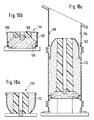
- FIG. 10a illustrates the casting of the refractory in a sheath according to FIG. 4 to produce the upper ball joint 136. This phase is identical to that described with reference to FIG. 6a and does not require further explanation.
- FIG. 10b there is the intermediate phase illustrated in FIG. 10b and representing the separate pouring of the plate 144 from the lower articulation 140.
- the sheath 158 is first placed on a wooden mold 168, the housing provided for the joint 160 ( Figure 9) being oriented downwards.
- the profile of the upper face of this mold 168 is complementary to that of the refractory lining of the plate 144.
- axially inside the sheath 158 is placed on the support 168 a form 169 of expanded synthetic material corresponding to the opening of the plate 144 and the refractory material is poured between this shape 169 and the sheath 158.
- After the casting and the removal of the mold 168 it is possible to immediately fix, for example glue the seal 160 (FIG. 9) in its housing inside the sheath 158.
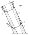
- FIG. 11 illustrates a third embodiment similar to that of FIG. 7 and comprising a central element 170 connected through an upper spherical articulation 176 to a ball joint 172 and by a lower spherical articulation 178 to a tube 174.
- the lower tube 174 and the lower joint 178 are identical to the embodiment of Figure 5 and, therefore, do not require additional description.
- the central element 170 for its part, is similar to that of the embodiment of FIG. 7 insofar as it does not have a flange to make its connection with the tube 174.
- a detachable connection is provided between the shielding of the central element 170 and that of the pipe 174.
- the upper connector 180 of the compensator 182 is welded to the shield of the central element 170 at the level of a metal shoulder 184 on which is also welded the sheath of the ball joint of the joint 178.
- the solidity of the welding of the fitting 180 on the shoulder 184 must be a compromise between the need to have to undo the welding in the event of disassembly, on the one hand, and the need to seal and contain the internal pressure, on the other hand.
- FIG. 11 offers the advantage of the same simplicity of manufacture as that of the mode of Figure 5 embodiment, that is to say not to have to flow the lower tube in two stages and the advantage of the embodiment of Figure 7, to spare the connecting flange between the central element and the lower tubing.
- the embodiment of Figure 11 requires the presence of a weld to contain the internal pressure.
- This embodiment according to FIG. 13 also includes a central tubular element 200 connected through a spherical articulation higher to a ball joint 202 and through a lower spherical articulation 208 to a lower tubing 204.
- the two plates of the joints 206 and 208 are provided at the opposite ends of the central element 200, the ball joint of the lower joint 208 forming part of the pipe 204.
- the upper joints and lower are therefore oriented in the opposite direction as recommended by document EP-A1-0363576, which also makes it possible to take advantage of the advantages described in this document.
- this embodiment makes it possible to spare the flange of the central element 200, without requiring a detachable weld between the shielding of the latter and the shielding of the lower tube 204 and without requiring having to sink the tubing 204 in two stages as confirmed by the description of the different phases of manufacturing which will be described below with reference to Figures 13a, 13b and 13c.
- the production of the ball joint 202 illustrated in FIG. 13a is in accordance with the manufacture of the ball joints of the preceding embodiments.
- Figure 13b illustrates the manufacture of the central element 200.
- the metal shielding thereof which is part of that of the lower tube 204 is placed on a wooden mold which supports it by means of the housing of the gasket. 'lower joint 208.
- the mold 210 is supported by a base 212 which is preferably provided with a support supporting the shielding of the pipe 204 by means of an internal stop 216 which will later serve as a fixing support of the patella sheath.
- the profile of the upper face of the mold 210 is complementary to that of the base of the lower joint. It is therefore sufficient to place axially inside the shielding of the element 200 and on the mold 210 a shape 218 made of expanded synthetic material and corresponding to the inner channel of the central element 200.
- the profile of the plate 220 of the upper articulation is formed in the refractory material cast by removing the material cast before it hardening, for example using a scraper having the complementary profile of the plate 220.
- the structure produced in accordance with FIG. 13b is then turned over and placed on a base 222 which is preferably a wooden mold used to shape the plates of the joints. The structure is therefore carried by the plate 220 on the mold 222. We then proceed to the installation of the seal 224 by sticking it in its housing provided for this purpose on the inner surface of the shield of the element 200.
- a disc 226 of expanded synthetic material the thickness of which corresponds to the axial width of the transverse slot of the joint 208 between its ball joint and the plate .
- a ball joint sheath 72 is then introduced from above into the shielding of the tube 204 by placing it and welding it by its edge 84 to the stop 216 provided for this purpose on the interior surface of the shielding.
- an expanded plastic form is axially placed on the disc 226, the configuration of which corresponds to the passage channel of the tube 204.
- the refractory material then simply flows into the annular space around this form by using the sheath. 72 as a mold.
- the central element 200 and the tubing 204 are ready for assembly, the interior shapes as well as the disc 226 being able to remain in place being given that they will burn out automatically when the blower holder is put into service.
Landscapes
- Chemical & Material Sciences (AREA)
- Engineering & Computer Science (AREA)
- Manufacturing & Machinery (AREA)
- Materials Engineering (AREA)
- Metallurgy (AREA)
- Organic Chemistry (AREA)
- Joints Allowing Movement (AREA)
- Furnace Housings, Linings, Walls, And Ceilings (AREA)
- Manufacture Of Motors, Generators (AREA)
- Heat Treatment Of Articles (AREA)
- Air Supply (AREA)
- Furnace Charging Or Discharging (AREA)
- Thermal Insulation (AREA)
- Tunnel Furnaces (AREA)
- Thermotherapy And Cooling Therapy Devices (AREA)
- Direct Air Heating By Heater Or Combustion Gas (AREA)
- Carbon Steel Or Casting Steel Manufacturing (AREA)
Applications Claiming Priority (3)
| Application Number | Priority Date | Filing Date | Title |
|---|---|---|---|
| LU87838A LU87838A1 (fr) | 1990-11-09 | 1990-11-09 | Dispositif d'injection d'air prechauffe dans un four a cuve et procede de fabrication de rotules convexes d'articulations spheriques |
| BR919104978A BR9104978A (pt) | 1990-11-09 | 1991-11-08 | Dispositivo de injecao de ar pre-aquecido em um forno de cuba e processo de fabricacao de rotulas convexas de articulacao esfericas |
| LU87838 | 1991-11-09 |
Publications (2)
| Publication Number | Publication Date |
|---|---|
| EP0484720A1 EP0484720A1 (fr) | 1992-05-13 |
| EP0484720B1 true EP0484720B1 (fr) | 1995-06-28 |
Family
ID=25664466
Family Applications (1)
| Application Number | Title | Priority Date | Filing Date |
|---|---|---|---|
| EP91117866A Expired - Lifetime EP0484720B1 (fr) | 1990-11-09 | 1991-10-19 | Dispositif d'injection d'air préchauffé dans un four à cuve et procédé de fabrication de rotules convexes d'articulations sphériques |
Country Status (10)
| Country | Link |
|---|---|
| EP (1) | EP0484720B1 (cs) |
| CN (1) | CN1044006C (cs) |
| AT (1) | ATE124462T1 (cs) |
| AU (1) | AU637939B2 (cs) |
| BR (1) | BR9104978A (cs) |
| CA (1) | CA2053935C (cs) |
| CZ (1) | CZ284580B6 (cs) |
| DE (1) | DE4136649C2 (cs) |
| ES (1) | ES2089085T3 (cs) |
| LU (1) | LU87838A1 (cs) |
Families Citing this family (3)
| Publication number | Priority date | Publication date | Assignee | Title |
|---|---|---|---|---|
| LU88241A1 (fr) * | 1993-03-31 | 1994-10-03 | Wurth Paul Sa | Dispositif d'injection d'air préchauffé dans un four à cuve |
| DE102010015842A1 (de) | 2010-03-05 | 2011-09-08 | Z & J Technologies Gmbh | Heißwinddüsenstock für einen Schachtofen, insbesondere Hochofen |
| FR3000133B1 (fr) * | 2012-12-26 | 2015-01-16 | Renault Sa | Ligne d'echappement de vehicule automobile comportant une rotule perfectionnee |
Family Cites Families (5)
| Publication number | Priority date | Publication date | Assignee | Title |
|---|---|---|---|---|
| BE632354A (cs) * | ||||
| US1405683A (en) * | 1919-07-07 | 1922-02-07 | David T Croxton | Tuyere stock |
| LU63079A1 (cs) * | 1971-04-29 | 1971-08-27 | ||
| US3766868A (en) * | 1972-02-22 | 1973-10-23 | Anciens Etablissements P Warth | Tuyere stock for furnaces |
| AU608987B2 (en) * | 1988-07-19 | 1991-04-18 | Paul Wurth S.A. | Device for injecting preheated air in a shaft furnace |
-
1990
- 1990-11-09 LU LU87838A patent/LU87838A1/fr unknown
-
1991
- 1991-10-18 AU AU85929/91A patent/AU637939B2/en not_active Ceased
- 1991-10-19 AT AT91117866T patent/ATE124462T1/de not_active IP Right Cessation
- 1991-10-19 EP EP91117866A patent/EP0484720B1/fr not_active Expired - Lifetime
- 1991-10-19 ES ES91117866T patent/ES2089085T3/es not_active Expired - Lifetime
- 1991-10-22 CA CA002053935A patent/CA2053935C/en not_active Expired - Lifetime
- 1991-11-07 DE DE4136649A patent/DE4136649C2/de not_active Expired - Lifetime
- 1991-11-08 BR BR919104978A patent/BR9104978A/pt not_active IP Right Cessation
- 1991-11-08 CN CN91110568.9A patent/CN1044006C/zh not_active Expired - Lifetime
- 1991-11-08 CZ CS913401A patent/CZ284580B6/cs not_active IP Right Cessation
Also Published As
| Publication number | Publication date |
|---|---|
| CS340191A3 (en) | 1992-05-13 |
| ES2089085T3 (es) | 1996-10-01 |
| DE4136649A1 (de) | 1992-05-14 |
| CN1061655A (zh) | 1992-06-03 |
| AU8592991A (en) | 1992-05-14 |
| CA2053935A1 (en) | 1992-05-10 |
| CA2053935C (en) | 2002-12-10 |
| CZ284580B6 (cs) | 1999-01-13 |
| DE4136649C2 (de) | 2000-02-24 |
| EP0484720A1 (fr) | 1992-05-13 |
| LU87838A1 (fr) | 1992-08-25 |
| ATE124462T1 (de) | 1995-07-15 |
| AU637939B2 (en) | 1993-06-10 |
| CN1044006C (zh) | 1999-07-07 |
| BR9104978A (pt) | 1992-06-23 |
Similar Documents
| Publication | Publication Date | Title |
|---|---|---|
| EP0484720B1 (fr) | Dispositif d'injection d'air préchauffé dans un four à cuve et procédé de fabrication de rotules convexes d'articulations sphériques | |
| EP0618301B1 (fr) | Dispositif d'injection d'air préchauffé dans un four à cuve | |
| WO1992014962A1 (fr) | Conduite pour le transport de fluides, en particulier d'hydrocarbures | |
| EP0453739B1 (fr) | Dispositif d'injection d'air préchauffé dans un four à cuve | |
| EP0363576B1 (fr) | Dispositif d'injection d'air préchauffé dans un four à cuve | |
| WO2013068333A1 (fr) | Systeme de liaison etanche entre une tuyere et un busillon d'amenee de vent chaud pour un four a cuve, et haut fourneau siderurgique comportant un tel systeme | |
| EP0764220B1 (fr) | Dispositif de chargement a goulotte rotative pour un four a cuve | |
| FR2576389A1 (fr) | Dispositif de jonction entre deux tuyaux comportant des pieces d'appui escamotables | |
| CA1163657A (fr) | Element de tuyauterie constitutif d'un joint, procede et dispositif de fabrication de cet element | |
| EP0499562A1 (fr) | Virole de cylindre de coulée continue | |
| EP0019256A1 (fr) | Tuyau en fonte ductile à emboîtement | |
| BE1004282A6 (fr) | Dispositif de prechauffage d'une busette de coulee d'un metal en fusion et installation de coulee d'un metal equipee de ce dispositif. | |
| EP1197707B1 (fr) | Ensemble de deux conduits de gaz chauds raccordés au moyen d'un coupleur et procédé de raccordement | |
| EP0349513B1 (fr) | Bouclier d'isolation thermique destiné à permettre la réfection de cowpers et procédé pour sa mise en oeuvre | |
| EP0477119A1 (fr) | Dispositif intermédiaire pour la coulée de pièces moulées | |
| EP0015351B2 (fr) | Conduit de liaison entre l'intérieur et l'extérieur d'un four | |
| EP0498187B1 (fr) | Canon à argile pour machine à boucher les trous de coulée de fours à cuve | |
| EP2487020B1 (fr) | Procédé de raccordement de joints d'étanchéité | |
| FR2564484A1 (fr) | Dispositif de fixation souple et etanche de plaques de refroidissement pour haut fourneau | |
| EP0703028B1 (fr) | Dispositif d'alimentation en gaz inerte d'une busette interne pour récipients métallurgiques | |
| FR2649469A1 (fr) | Tube, notamment pour ligne d'echappement pour vehicule automobile et comportant au moins un organe de liaison | |
| EP0538113B1 (fr) | Rouleaux conducteurs de courant notamment pour lignes d'électrolyse | |
| LU87504A1 (fr) | Dispositif d'injection d'air prechauffe dans un four a cuve | |
| FR2547631A1 (fr) | Procede et dispositif de raccordement etanche par serrage thermique pour rendre solidaires deux pieces mecaniques | |
| EP0562957A1 (fr) | Inserts pour l'équipement de caissons étanches en matériaux composites |
Legal Events
| Date | Code | Title | Description |
|---|---|---|---|
| PUAI | Public reference made under article 153(3) epc to a published international application that has entered the european phase |
Free format text: ORIGINAL CODE: 0009012 |
|
| AK | Designated contracting states |
Kind code of ref document: A1 Designated state(s): AT BE ES FR GB IT NL SE |
|
| 17P | Request for examination filed |
Effective date: 19920918 |
|
| 17Q | First examination report despatched |
Effective date: 19941012 |
|
| GRAA | (expected) grant |
Free format text: ORIGINAL CODE: 0009210 |
|
| AK | Designated contracting states |
Kind code of ref document: B1 Designated state(s): AT BE ES FR GB IT NL SE |
|
| REF | Corresponds to: |
Ref document number: 124462 Country of ref document: AT Date of ref document: 19950715 Kind code of ref document: T |
|
| ITF | It: translation for a ep patent filed | ||
| GBT | Gb: translation of ep patent filed (gb section 77(6)(a)/1977) |
Effective date: 19950829 |
|
| REG | Reference to a national code |
Ref country code: ES Ref legal event code: BA2A Ref document number: 2089085 Country of ref document: ES Kind code of ref document: T3 |
|
| PLBE | No opposition filed within time limit |
Free format text: ORIGINAL CODE: 0009261 |
|
| STAA | Information on the status of an ep patent application or granted ep patent |
Free format text: STATUS: NO OPPOSITION FILED WITHIN TIME LIMIT |
|
| 26N | No opposition filed | ||
| REG | Reference to a national code |
Ref country code: ES Ref legal event code: FG2A Ref document number: 2089085 Country of ref document: ES Kind code of ref document: T3 |
|
| REG | Reference to a national code |
Ref country code: ES Ref legal event code: FG2A Ref document number: 2089085 Country of ref document: ES Kind code of ref document: T3 |
|
| REG | Reference to a national code |
Ref country code: GB Ref legal event code: IF02 |
|
| PGFP | Annual fee paid to national office [announced via postgrant information from national office to epo] |
Ref country code: SE Payment date: 20091028 Year of fee payment: 19 |
|
| PGFP | Annual fee paid to national office [announced via postgrant information from national office to epo] |
Ref country code: BE Payment date: 20090916 Year of fee payment: 19 Ref country code: NL Payment date: 20090917 Year of fee payment: 19 |
|
| PGFP | Annual fee paid to national office [announced via postgrant information from national office to epo] |
Ref country code: IT Payment date: 20091027 Year of fee payment: 19 |
|
| PGFP | Annual fee paid to national office [announced via postgrant information from national office to epo] |
Ref country code: FR Payment date: 20100927 Year of fee payment: 20 |
|
| PGFP | Annual fee paid to national office [announced via postgrant information from national office to epo] |
Ref country code: GB Payment date: 20100916 Year of fee payment: 20 |
|
| PGFP | Annual fee paid to national office [announced via postgrant information from national office to epo] |
Ref country code: AT Payment date: 20100916 Year of fee payment: 20 |
|
| BERE | Be: lapsed |
Owner name: S.A. PAUL *WURTH Effective date: 20101031 |
|
| REG | Reference to a national code |
Ref country code: NL Ref legal event code: V1 Effective date: 20110501 |
|
| PGFP | Annual fee paid to national office [announced via postgrant information from national office to epo] |
Ref country code: ES Payment date: 20100916 Year of fee payment: 20 |
|
| PG25 | Lapsed in a contracting state [announced via postgrant information from national office to epo] |
Ref country code: NL Free format text: LAPSE BECAUSE OF NON-PAYMENT OF DUE FEES Effective date: 20110501 Ref country code: BE Free format text: LAPSE BECAUSE OF NON-PAYMENT OF DUE FEES Effective date: 20101031 |
|
| PG25 | Lapsed in a contracting state [announced via postgrant information from national office to epo] |
Ref country code: SE Free format text: LAPSE BECAUSE OF NON-PAYMENT OF DUE FEES Effective date: 20101020 |
|
| REG | Reference to a national code |
Ref country code: GB Ref legal event code: PE20 Expiry date: 20111018 |
|
| PG25 | Lapsed in a contracting state [announced via postgrant information from national office to epo] |
Ref country code: IT Free format text: LAPSE BECAUSE OF NON-PAYMENT OF DUE FEES Effective date: 20101019 |
|
| REG | Reference to a national code |
Ref country code: AT Ref legal event code: MK07 Ref document number: 124462 Country of ref document: AT Kind code of ref document: T Effective date: 20111019 |
|
| PG25 | Lapsed in a contracting state [announced via postgrant information from national office to epo] |
Ref country code: GB Free format text: LAPSE BECAUSE OF EXPIRATION OF PROTECTION Effective date: 20111018 |
|
| REG | Reference to a national code |
Ref country code: ES Ref legal event code: FD2A Effective date: 20120510 |
|
| PG25 | Lapsed in a contracting state [announced via postgrant information from national office to epo] |
Ref country code: ES Free format text: LAPSE BECAUSE OF EXPIRATION OF PROTECTION Effective date: 20111020 |