EP0484764A1 - Vorrichtung zum Messen der Dimensionen eines Objektes - Google Patents
Vorrichtung zum Messen der Dimensionen eines Objektes Download PDFInfo
- Publication number
- EP0484764A1 EP0484764A1 EP91118223A EP91118223A EP0484764A1 EP 0484764 A1 EP0484764 A1 EP 0484764A1 EP 91118223 A EP91118223 A EP 91118223A EP 91118223 A EP91118223 A EP 91118223A EP 0484764 A1 EP0484764 A1 EP 0484764A1
- Authority
- EP
- European Patent Office
- Prior art keywords
- measuring
- nozzle
- pressure transducer
- inlet
- outlet
- Prior art date
- Legal status (The legal status is an assumption and is not a legal conclusion. Google has not performed a legal analysis and makes no representation as to the accuracy of the status listed.)
- Withdrawn
Links
- 239000007788 liquid Substances 0.000 claims abstract description 29
- 238000005259 measurement Methods 0.000 claims abstract description 26
- 230000001105 regulatory effect Effects 0.000 claims description 3
- 239000012530 fluid Substances 0.000 abstract description 5
- 238000000034 method Methods 0.000 abstract description 2
- 238000003754 machining Methods 0.000 description 8
- 230000008901 benefit Effects 0.000 description 5
- 238000004519 manufacturing process Methods 0.000 description 4
- 230000000694 effects Effects 0.000 description 3
- 239000004065 semiconductor Substances 0.000 description 3
- 238000005520 cutting process Methods 0.000 description 2
- 235000021183 entrée Nutrition 0.000 description 2
- 230000006872 improvement Effects 0.000 description 2
- 239000012528 membrane Substances 0.000 description 2
- 230000035515 penetration Effects 0.000 description 2
- 230000035484 reaction time Effects 0.000 description 2
- 230000035945 sensitivity Effects 0.000 description 2
- 206010013082 Discomfort Diseases 0.000 description 1
- 241001080024 Telles Species 0.000 description 1
- 240000008042 Zea mays Species 0.000 description 1
- 230000003321 amplification Effects 0.000 description 1
- 238000013459 approach Methods 0.000 description 1
- 238000001816 cooling Methods 0.000 description 1
- 239000002173 cutting fluid Substances 0.000 description 1
- 230000007423 decrease Effects 0.000 description 1
- 238000010586 diagram Methods 0.000 description 1
- 238000004880 explosion Methods 0.000 description 1
- 238000001914 filtration Methods 0.000 description 1
- 230000036541 health Effects 0.000 description 1
- 239000000463 material Substances 0.000 description 1
- 239000000203 mixture Substances 0.000 description 1
- 238000003199 nucleic acid amplification method Methods 0.000 description 1
- 230000010355 oscillation Effects 0.000 description 1
- 230000003071 parasitic effect Effects 0.000 description 1
- 239000003208 petroleum Substances 0.000 description 1
- 238000003825 pressing Methods 0.000 description 1
- 230000004044 response Effects 0.000 description 1
- 239000000523 sample Substances 0.000 description 1
- 238000005507 spraying Methods 0.000 description 1
- 239000000126 substance Substances 0.000 description 1
- 230000002277 temperature effect Effects 0.000 description 1
- UONOETXJSWQNOL-UHFFFAOYSA-N tungsten carbide Chemical compound [W+]#[C-] UONOETXJSWQNOL-UHFFFAOYSA-N 0.000 description 1
Images


Classifications
-
- G—PHYSICS
- G01—MEASURING; TESTING
- G01B—MEASURING LENGTH, THICKNESS OR SIMILAR LINEAR DIMENSIONS; MEASURING ANGLES; MEASURING AREAS; MEASURING IRREGULARITIES OF SURFACES OR CONTOURS
- G01B13/00—Measuring arrangements characterised by the use of fluids
- G01B13/08—Measuring arrangements characterised by the use of fluids for measuring diameters
- G01B13/10—Measuring arrangements characterised by the use of fluids for measuring diameters internal diameters
Definitions
- the present invention relates to a device for measuring the dimensions of a part comprising a circuit in which a liquid circulates, said circuit comprising a first branch provided with an inlet nozzle and at least one measuring nozzle directed towards the part the dimensions of which are to be measured, and a second branch provided with an inlet nozzle and opening into a reference outlet nozzle, a pressure transducer delivering an electrical signal representative of the difference in pressures prevailing in the two branches of the circuit and means for connecting the inlet nozzles to a regulated pressure source.
- the device of the cited document consists in supplying, via a pressure regulator 1, a pneumatic circuit comprising a first branch 15 provided with an inlet nozzle 16 and a spindle measuring device 4 capable for example of being introduced into a bore 5 whose diameter must be measured, as well as a second branch 19 provided with an inlet nozzle 20 opening into a reference nozzle 21, the flow rate of which can be adjustable.
- a pressure transducer 22 connected between the branches 15 and 19 delivers an electrical signal representative of the difference in pressures prevailing in these branches, which is amplified by an amplifying device 10 before being supplied for example to an indicating device 11.
- the object of the invention described in document EP 0 109 936 is to propose an improvement of the known devices, which makes it possible to considerably reduce the measurement noise, as well as the time constant of the measurement device and the sensitivity to vibrations, while allowing a simple and independent adjustment of the sensitivity of the device and zero of the output signal.
- the cited invention provides for using a differential pressure transducer with semiconductor elements and for arranging the assembly of the transducer and the pneumatic circuit inside the measuring pin. While leaving the freedom to define the pneumatic circuit optimally, so as to limit the production of measurement noise as much as possible, this solution makes it possible to obtain a measurement device completely insensitive to vibrations, and whose time constant, the order of a tenth of a second is sufficiently low to allow extremely rapid measurements, for example between two penetrations in a part of an oscillating machining tool, or to measure discontinuous surfaces of a part in movement.
- the cutting fluid used to cool and lubricate the workpiece is often a petroleum-based mixture. If pressurized air is used to measure the size of the part at the same time as it is machined, the cooling oil can be sprayed by air and thus cause explosions if the cutting tool sparks. Very generally also, the cutting liquid thus sprayed can be harmful to health or, at least, cause general discomfort and soiling of objects in the environment of the machine.
- the time constant of the measuring device is on the order of a tenth of a second (100 ms).
- This reaction time is linked to the fact that the fluid used is essentially compressible air.
- the time reached by 100 ms slows down the machining process, for example in machining rectification of internal bores or the back and forth of the grinding wheel could be much more frequent for a determined period of time if the residence time of the measuring device inside the part could be shortened.
- Due to the elasticity of the air used for the measurement the pressures take a certain time to establish and stabilize at the measurement locations, which therefore prevents rapid machining since it is necessary to carry out a measurement which lasts relatively long after each pass of the tool.
- the Hydrocompar device mentioned above used inlet nozzles identical to those used on devices using air with the disadvantage of creating undesirable turbulence for the liquid. However, this turbulence causes a significant background noise on the pressure transducer.
- the measuring device is characterized in that the inlet nozzles are equipped with means for delivering at their outlet a flow of the liquid producing minimum noise on the electrical signal from the pressure transducer.
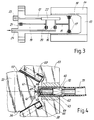
- FIGS. 2 and 3 show two different embodiments of the invention in which the measuring device comprises a circuit in which a liquid circulates.
- This circuit comprises a first branch 15 provided with an inlet nozzle 16 and at least one measuring nozzle 17 directed towards the part 14 whose internal dimensions are to be measured 13.
- the circuit also comprises a second branch 19 provided with an inlet nozzle 20 and opening into a reference outlet nozzle 21.
- the device also includes a pressure transducer 22 delivering an electrical signal on its terminals 23, a signal which is representative of the difference in pressures prevailing in branches 15 and 19 of the circuit.
- Figures 2 and 3 also show that a nozzle 24 makes it possible to connect the inlet nozzles 16 and 20 to a regulated pressure source (not shown).
- FIGS. 2 and 3 show devices equipped with a measuring pin 2, respectively 12, on the surface of which open measuring nozzles 17.
- the system comprises a measurement unit 3 comprising the inlet nozzles 16 and 20, the reference outlet nozzle 21 and the pressure transducer 22.
- a flexible pipe 9 connects the pin 2 to unit 3.
- pins of any dimensions, or even very small dimensions can be used with a unit of measurement which remains standard. It has already been said that, since the measurement fluid is liquid, the reaction time of the system is extremely short, of the order of 10 ms and this within the limits of reasonable length of the pipe 9.
- the measurement nozzles 17, the input nozzles 16 and 20, the reference output nozzle 21 and the pressure transducer 22 are housed entirely inside the spindle 12.
- the measuring pin 2, 12 has a cylindrical end 18 for measuring the diameter of a bore 13.
- Two measuring nozzles 17 open symmetrically in two opposite places of the cylindrical end 18 .
- the differential pressure transducer 22 is a semiconductor element. It essentially consists of a semiconductor wafer in which a membrane has been produced by chemical machining processes, as well as a bridge of piezoresistors formed on the membrane and of amplifying elements. Such pressure transducers, and their manufacture are described, for example, in French patent application 2,266,314. They can be obtained from the company Sensym under the reference SPX 200.
- FIG 7 there is shown schematically a control circuit of the differential pressure transducer used in the device of the invention.
- This transducer is shown schematically in the frame in dotted lines 40 by a bridge of piezoresistors 41 which are supplied via a supply 47, preferably a current source.
- An operational amplifier 42 one of the inputs of which is controlled by means of an adjustable potentiometer 43 makes it possible to adjust the zero of the output signal, while the gain of the amplification is defined by the potentiometer 44 which acts on the amplifier 45, at the output 46 from which the signal representative of the dimension measured can be collected.
- the dimensional and dynamic characteristics of said device allow it to be applied to many types of measurements in the field of machining of parts.
- it is particularly well suited to be mounted inside the workpiece headstock of an internal grinding machine, and kinematically connected to the tool headstock, so as to measure the diameter of the bore of the workpiece rectified during each oscillation of the tool, and thus allow to continuously adjust the advance of the grinding wheel, throughout the grinding operation, and to stop it when the nominal dimension of the bore is reached.
- FIG. 4 shows a measurement sensor 70 used on the device according to the invention, a sensor suitable for measuring the diameters of cylindrical parts.
- the device comprises a head 55 which has an opening provided with two rectilinear edges 56 and 57 arranged in V. The edges press against the part 52 and are here materialized by the generators of cylindrical bars or keys 58 and 59 made of hard material , tungsten carbide for example.
- the sensor 70 arranged along the bisector of the angle formed by the edges 56 and 57, this sensor delivering, in a manner known per se, a signal representative of the diameter of the workpiece.
- the sensor 70 acting as a measuring nozzle, here is a so-called indirect leak sensor.
- a liquid 65 under pressure is injected into the flexible pipe 71 which is fitted into the sensor 70 proper.
- the sensor has a chamber 62 in which a piston 63 moves. This piston is provided with channels 64 to let the liquid pass.
- the piston ends with a cone 66 and a feeler 67.
- the piston closes the orifice 68 by pressing the cone 63 on a flange 69 presented by this orifice 68.
- the piston 67 is pushed to the right , which occurs when the diameter of the part 52 decreases under the effect of the work of the grinding wheel, liquid can flow according to the arrows 60 and 61. At this time, the liquid flow varies, which has for consequence of varying the pressure which is then a measure of the penetration of the probe into the sensor.
- the nozzle 80 of Figure 5 is of a form commonly used to be mounted in pneumatic devices.
- the nozzle 80 is screwed into a thread 73 made either in the measurement unit 3 ( Figure 2) or in the spindle 12 ( Figure 3).
- Such a nozzle is used as an inlet nozzle 16 and 20 and generally comprises an inlet cone 82 and a constriction 81. If a liquid is injected into the channel 83 in the direction of arrow A, the constriction 81 will have effect of increasing the speed of the liquid at the outlet 84 of the nozzle in the direction B and, consequently, of creating undesirable turbulence, which causes a significant background noise on the pressure transducer.
- the turbulence is produced by a high speed jet at B relative to region C where this speed is less important.
- the nozzle of Figure 6 is designed to avoid this turbulence and to ensure a uniform flow of liquid at its outlet.
- This nozzle has two parts.
- the first part 80 is similar to that of FIG. 5 with its inlet cone 82 and its throttle 81.
- This first part is screwed into a thread 73 practiced in a second part 74 itself driven into the inlet channel 83.
- This second part 74 comprises a chamber 76 and at least one outlet duct 75 practiced substantially perpendicular to the axis that has the constriction 81. We s 'Arranges so that the section of the conduit 75 is larger than the section of the throttle 81.
- the invention is not limited to the nozzle described in FIG. 6, any other shape that can be imagined which makes it possible to deliver at the outlet of the nozzle a flow of the liquid producing minimum noise on the electrical signal coming from the pressure transducer.
Landscapes
- Physics & Mathematics (AREA)
- General Physics & Mathematics (AREA)
- Measuring Arrangements Characterized By The Use Of Fluids (AREA)
Applications Claiming Priority (2)
| Application Number | Priority Date | Filing Date | Title |
|---|---|---|---|
| FR9013763 | 1990-11-05 | ||
| FR9013763A FR2668823B1 (fr) | 1990-11-05 | 1990-11-05 | Dispositif de mesure des dimensions d'une piece. |
Publications (1)
| Publication Number | Publication Date |
|---|---|
| EP0484764A1 true EP0484764A1 (de) | 1992-05-13 |
Family
ID=9401912
Family Applications (1)
| Application Number | Title | Priority Date | Filing Date |
|---|---|---|---|
| EP91118223A Withdrawn EP0484764A1 (de) | 1990-11-05 | 1991-10-25 | Vorrichtung zum Messen der Dimensionen eines Objektes |
Country Status (4)
| Country | Link |
|---|---|
| US (1) | US5212980A (de) |
| EP (1) | EP0484764A1 (de) |
| JP (1) | JPH0510740A (de) |
| FR (1) | FR2668823B1 (de) |
Cited By (1)
| Publication number | Priority date | Publication date | Assignee | Title |
|---|---|---|---|---|
| US5653037A (en) * | 1994-11-18 | 1997-08-05 | Nissan Motor Co., Ltd. | Apparatus and method for measurement of tapped hole |
Families Citing this family (10)
| Publication number | Priority date | Publication date | Assignee | Title |
|---|---|---|---|---|
| ATE413255T1 (de) * | 2000-09-05 | 2008-11-15 | Makino Inc | Werkstückmessvorrichtung und verfahren |
| GB2372324B (en) * | 2000-11-10 | 2004-12-22 | Leamount Ltd | Air flow measurement |
| JP4840631B2 (ja) * | 2001-08-29 | 2011-12-21 | 株式会社東京精密 | 内径測定方法及び装置 |
| US6708566B1 (en) | 2003-02-21 | 2004-03-23 | Robert Bosch Gmbh | Air gauge for measuring the geometry of precision machined fluid passages |
| US7861432B1 (en) * | 2006-12-05 | 2011-01-04 | Alan Heimlich | Method and apparatus for hole measurement |
| DE102008007593A1 (de) * | 2008-01-25 | 2009-09-03 | Basar Gmbh | Vorrichtung zur Geometriemessung an einem Werkstück und Verfahren zur Geometriemessung an einem Werkstück |
| US20090211338A1 (en) * | 2008-02-21 | 2009-08-27 | Mori Seiki Usa, Inc. | Measuring Apparatus and Associated Method |
| US9427843B2 (en) * | 2008-02-21 | 2016-08-30 | Mori Seiki Co., Ltd | Measuring apparatus and method |
| JP6883325B2 (ja) * | 2017-08-09 | 2021-06-09 | アドバンス電気工業株式会社 | 液マイクロメータ |
| CN110514155A (zh) * | 2019-08-30 | 2019-11-29 | 中国航发动力股份有限公司 | 一种用于测量高精度浅孔直径的测量装置及采用其测量浅孔的方法 |
Citations (3)
| Publication number | Priority date | Publication date | Assignee | Title |
|---|---|---|---|---|
| US2497236A (en) * | 1944-06-08 | 1950-02-14 | Sheffield Corp | Size gauging device |
| US3494078A (en) * | 1966-06-01 | 1970-02-10 | Katsumi Miyamoto | Automatic sizing device of internal grinder |
| EP0109936A1 (de) * | 1982-11-22 | 1984-05-30 | Meseltron S.A. | Pneumatische Einrichtung zur Massbestimmung eines Werkstücks |
Family Cites Families (6)
| Publication number | Priority date | Publication date | Assignee | Title |
|---|---|---|---|---|
| US2513374A (en) * | 1948-01-07 | 1950-07-04 | Taft Pierce Mfg Company | Measuring apparatus for gauge determination of dimensions of bodies with flow of fluid under pressure from an orifice |
| DE1096620B (de) * | 1955-07-26 | 1961-01-05 | Opel Adam Ag | Pneumatisches Messgeraet |
| GB937054A (en) * | 1961-04-24 | 1963-09-18 | Thomas Mercer Ltd | Improvements relating to pneumatic gauging apparatus |
| GB1022145A (en) * | 1963-02-05 | 1966-03-09 | Thomas Mercer Ltd | Apparatus for pneumatically gauging the calibre of a hole in a workpiece |
| DE2700439A1 (de) * | 1977-01-07 | 1978-07-13 | Mo Instrumentalnyj Z Kalibr | Pneumatische einrichtung zum messen von laengenabmessungen |
| US4538449A (en) * | 1982-11-22 | 1985-09-03 | Meseltron S.A. | Pneumatic measuring device for measuring workpiece dimension |
-
1990
- 1990-11-05 FR FR9013763A patent/FR2668823B1/fr not_active Expired - Lifetime
-
1991
- 1991-10-25 EP EP91118223A patent/EP0484764A1/de not_active Withdrawn
- 1991-11-04 US US07/787,144 patent/US5212980A/en not_active Expired - Fee Related
- 1991-11-05 JP JP3315292A patent/JPH0510740A/ja active Pending
Patent Citations (3)
| Publication number | Priority date | Publication date | Assignee | Title |
|---|---|---|---|---|
| US2497236A (en) * | 1944-06-08 | 1950-02-14 | Sheffield Corp | Size gauging device |
| US3494078A (en) * | 1966-06-01 | 1970-02-10 | Katsumi Miyamoto | Automatic sizing device of internal grinder |
| EP0109936A1 (de) * | 1982-11-22 | 1984-05-30 | Meseltron S.A. | Pneumatische Einrichtung zur Massbestimmung eines Werkstücks |
Cited By (1)
| Publication number | Priority date | Publication date | Assignee | Title |
|---|---|---|---|---|
| US5653037A (en) * | 1994-11-18 | 1997-08-05 | Nissan Motor Co., Ltd. | Apparatus and method for measurement of tapped hole |
Also Published As
| Publication number | Publication date |
|---|---|
| US5212980A (en) | 1993-05-25 |
| FR2668823A1 (fr) | 1992-05-07 |
| JPH0510740A (ja) | 1993-01-19 |
| FR2668823B1 (fr) | 1992-12-31 |
Similar Documents
| Publication | Publication Date | Title |
|---|---|---|
| EP0484764A1 (de) | Vorrichtung zum Messen der Dimensionen eines Objektes | |
| EP0198731B1 (de) | Ultraschallwandler zum Kontaktieren mit einer Trennwand auf hoher Temperatur und Anwendung desselben | |
| EP0172067B1 (de) | Vorrichtung zur Ultraschallprüfung von zum Teil eingetauchten Bestandteilen | |
| EP0475923A1 (de) | Vorrichtung zur Kraftregulierung der Niederhalter einer Presse | |
| FR2594972A1 (fr) | Regulateur de pression avec capteur integre | |
| JPH0862128A (ja) | 噴霧器 | |
| FR2666892A1 (fr) | Capteur optique de temperature. | |
| EP0100716B1 (de) | Koordinatentaster mit einem Laser | |
| FR2868970A1 (fr) | Dispositif acoustique, sonde de jaugeage de liquide equipee d'un tel dispositif et systeme de jaugeage de liquide pourvu d'une telle sonde | |
| EP0109936B1 (de) | Pneumatische Einrichtung zur Massbestimmung eines Werkstücks | |
| FR2474194A1 (fr) | Regulateur de pression pour un circuit hydraulique ouvert | |
| EP0014164B1 (de) | Viskosimeter und Viskosistat | |
| EP2751633B1 (de) | Einstufiger druckminderer für gas | |
| FR2537269A1 (fr) | Dispositif de mesure pneumatique des dimensions d'une piece | |
| WO2007031682A1 (fr) | Procede et dispositif de reglage de la profondeur d'emmanchement d'un outil dans un porte-outil | |
| EP0194937B1 (de) | Kolbentyp-Drucksensor | |
| EP0042432A1 (de) | Gasmassenströmungsdetektor und ein diesen benutzendes kraftstoffinjektionssystem für eine verbrennungskraftmaschine | |
| EP0446547B1 (de) | Pneumatische Messeinrichtung | |
| FR2781898A1 (fr) | Dispositif de reglage de vitesse de rotation pour outil rotatif pneumatique | |
| FR2604053A1 (fr) | Arroseur rotatif, en particulier pour l'irrigation individuelle de plantes. | |
| FR2751752A1 (fr) | Dispositif capteur, notamment pour vehicule automobile | |
| FR2712167A1 (fr) | Capteur de régulation de débit pour aspirateur. | |
| FR3074579B1 (fr) | Procede de fabrication simplifie d'un capteur de pression differentielle | |
| FR2886011A1 (fr) | Dispositif pour mesurer le debit d'un gaz et son application a la mesure du debit d'oxygene dans des installations medicales | |
| CH703905A1 (fr) | Pige, jauge de précision et support pour de telles jauges. |
Legal Events
| Date | Code | Title | Description |
|---|---|---|---|
| PUAI | Public reference made under article 153(3) epc to a published international application that has entered the european phase |
Free format text: ORIGINAL CODE: 0009012 |
|
| AK | Designated contracting states |
Kind code of ref document: A1 Designated state(s): CH DE ES GB IT LI SE |
|
| 17P | Request for examination filed |
Effective date: 19920529 |
|
| 17Q | First examination report despatched |
Effective date: 19940504 |
|
| RAP1 | Party data changed (applicant data changed or rights of an application transferred) |
Owner name: SOCIETE INDUSTRIELLE DE LIAISONS ELECTRIQUES - SIL |
|
| STAA | Information on the status of an ep patent application or granted ep patent |
Free format text: STATUS: THE APPLICATION IS DEEMED TO BE WITHDRAWN |
|
| 18D | Application deemed to be withdrawn |
Effective date: 19940914 |