EP0484773A1 - Distributeur de fluide - Google Patents
Distributeur de fluide Download PDFInfo
- Publication number
- EP0484773A1 EP0484773A1 EP91118296A EP91118296A EP0484773A1 EP 0484773 A1 EP0484773 A1 EP 0484773A1 EP 91118296 A EP91118296 A EP 91118296A EP 91118296 A EP91118296 A EP 91118296A EP 0484773 A1 EP0484773 A1 EP 0484773A1
- Authority
- EP
- European Patent Office
- Prior art keywords
- stroke
- valve
- pump
- pump chamber
- discharge device
- Prior art date
- Legal status (The legal status is an assumption and is not a legal conclusion. Google has not performed a legal analysis and makes no representation as to the accuracy of the status listed.)
- Granted
Links
- 239000012530 fluid Substances 0.000 title abstract 6
- 230000001419 dependent effect Effects 0.000 claims abstract description 15
- 238000007789 sealing Methods 0.000 claims description 26
- 238000009423 ventilation Methods 0.000 claims description 7
- 238000007599 discharging Methods 0.000 claims 1
- 230000000694 effects Effects 0.000 description 4
- 230000006870 function Effects 0.000 description 2
- 239000007788 liquid Substances 0.000 description 2
- 238000005086 pumping Methods 0.000 description 2
- 239000004480 active ingredient Substances 0.000 description 1
- 238000013459 approach Methods 0.000 description 1
- 238000000889 atomisation Methods 0.000 description 1
- 238000007664 blowing Methods 0.000 description 1
- 238000004140 cleaning Methods 0.000 description 1
- 230000006835 compression Effects 0.000 description 1
- 238000007906 compression Methods 0.000 description 1
- 230000009969 flowable effect Effects 0.000 description 1
- 239000002991 molded plastic Substances 0.000 description 1
- 230000001151 other effect Effects 0.000 description 1
- 238000010992 reflux Methods 0.000 description 1
- 239000007779 soft material Substances 0.000 description 1
- 238000004804 winding Methods 0.000 description 1
Images


Classifications
-
- B—PERFORMING OPERATIONS; TRANSPORTING
- B05—SPRAYING OR ATOMISING IN GENERAL; APPLYING FLUENT MATERIALS TO SURFACES, IN GENERAL
- B05B—SPRAYING APPARATUS; ATOMISING APPARATUS; NOZZLES
- B05B11/00—Single-unit hand-held apparatus in which flow of contents is produced by the muscular force of the operator at the moment of use
- B05B11/01—Single-unit hand-held apparatus in which flow of contents is produced by the muscular force of the operator at the moment of use characterised by the means producing the flow
- B05B11/10—Pump arrangements for transferring the contents from the container to a pump chamber by a sucking effect and forcing the contents out through the dispensing nozzle
- B05B11/1001—Piston pumps
- B05B11/1016—Piston pumps the outlet valve having a valve seat located downstream a movable valve element controlled by a pressure actuated controlling element
- B05B11/1018—Piston pumps the outlet valve having a valve seat located downstream a movable valve element controlled by a pressure actuated controlling element and the controlling element cooperating with means for opening or closing the inlet valve
-
- B—PERFORMING OPERATIONS; TRANSPORTING
- B05—SPRAYING OR ATOMISING IN GENERAL; APPLYING FLUENT MATERIALS TO SURFACES, IN GENERAL
- B05B—SPRAYING APPARATUS; ATOMISING APPARATUS; NOZZLES
- B05B11/00—Single-unit hand-held apparatus in which flow of contents is produced by the muscular force of the operator at the moment of use
- B05B11/01—Single-unit hand-held apparatus in which flow of contents is produced by the muscular force of the operator at the moment of use characterised by the means producing the flow
- B05B11/10—Pump arrangements for transferring the contents from the container to a pump chamber by a sucking effect and forcing the contents out through the dispensing nozzle
- B05B11/1087—Combination of liquid and air pumps
Definitions
- the invention relates to a discharge device for at least one medium or for flowable media of essentially any physical state.
- Such a discharge device can indeed be used to discharge at least one medium via a pressure source, e.g. a pressure accumulator, operated and thereby operated only by manually opening an outlet valve, but expediently has a pump with a pump chamber for at least one medium, which is narrowed by manual force to convey media.
- the discharge device is preferably designed for one-handed use, the forces to be applied for the discharge being expediently only generated manually.
- the funding of at least one medium can be controlled for different purposes depending on the stroke.
- an outlet valve can only be opened by a stop at the end of the stroke in order to achieve a high discharge pressure.
- a pressure relief can also be provided at the end of the stroke, for example by unsealing a pump piston be provided to end the media funding as suddenly as possible.
- control means are conceivable for conveying a further medium, for example compressed gas, which is discharged in addition to a first medium, before the start and / or after the end of the conveyance of the first medium through the discharge opening or the like, or for the first and / or at least one discharge of the medium after a partial stroke after the start of the stroke.
- control means can be provided in order to convey at least a part of the conveyed further medium directly to a discharge nozzle and / or at least a part at a greater distance in front of it directly into an outlet channel leading to this discharge nozzle or to the discharge opening.
- This allows the media to be mixed at any point and / or e.g. for cleaning and blowing the outlet channel and the nozzle or for other purposes in succession.
- the invention is further based on the object of providing a discharge device of the type mentioned, by means of which disadvantages of known designs are avoided or effects of the type described can be achieved and which, in particular, ensures very precise control of the media delivery of at least one medium with a simple design.
- this object is solved by the features of claim 1.
- this start or the build-up of a discharge pressure can at least partially controlled in such a way that it only takes place after a first partial stroke.
- the media delivery can be interrupted one or more times, for example by relieving the discharge pressure in the pump chamber or the like.
- the free travel of the actuation stroke corresponding to the first partial stroke until the mechanical or path-dependent control unit responds can be used for numerous different functions.
- this empty path is used to build up a delivery pressure of at least one second medium and / or to open a pressure-dependent outlet valve for this second medium.
- This can e.g. Compressed air is initially biased in a pump chamber via the idle path and then advanced by opening the outlet valve, after which the first, e.g. liquid medium is also conveyed to the discharge opening.
- the delivery of the second medium can then take place continuously up to the end of the stroke of the actuation and, if necessary, a short time beyond, while the delivery of the first medium has already stopped before the end of the stroke.
- the mechanical control enables a very precise mutual adjustment of these functional sequences.
- the pressure in the pump chamber is expediently changed by opening and closing a slide-controlled control valve between a discharge pressure reaching for the discharge to the discharge opening and a pressure not sufficient for this, the valve outlet of this at least one control valve not to the outlet channel or to the outlet opening, but leads back to a media store via a return channel.
- No separate return channel is required for this if the inlet or suction channel for the pressure chamber is also used as the return channel becomes.
- no separate control valve is required if it is formed by a path-dependent controlled inlet valve for the pressure chamber, for which then no pressure-dependent inlet valve is required.
- the movable valve body of the inlet valve if it is formed by a pump piston, in particular a pre-suction piston of the pump.
- the medium is deflected twice in opposite directions, namely first in the discharge direction from the pump chamber and then in the opposite direction into the return channel.
- the training according to the invention is particularly suitable for discharge devices according to DE-OS 37 15 303, to which reference is made for further details and effects.
- the first idle or partial stroke is expediently more than a ninth to a quarter or a third of the total stroke and can also correspond to approximately half of the total stroke.
- the corresponding piston does not need to be guided with its inner circumference sealed to an inlet channel which projects substantially freely into the pump chamber, the inner circumference of the piston having a corresponding ring distance from the outer circumference of the inlet channel, the inlet channel in the jacket can be provided with through openings and / or can have longitudinal channels on the outer circumference via the associated longitudinal section.
- the piston runs close to the outer circumference of the inlet channel, which in this area has no through openings or slots or an enlarged collar.
- the component which determines the control characteristic of the control means and which is designed, for example, in the manner of a control curve can, is expediently formed by a part separate from an associated support or base body, so that the control characteristic can be changed as desired by selecting this component.
- the component can, for example, only be fastened by means of a plug-in and / or snap connection or be fixed in the fastening position by a retaining spring.
- the control valve expediently lies essentially entirely within the pump chamber.
- the passage cross section of the return channel can be changed depending on the stroke, e.g. in that a mandrel and / or part of a spring, e.g. a helical spring, which means that the return channel, which is free at the beginning of the stroke, is limited to a ring channel after a first short partial stroke and before closing the control valve.
- the return channel limited in this way which can also be helical due to the spring, then forms a return throttle, so that a pressure is built up in the pressure chamber by the time the control valve closes, but its level is lower than the discharge pressure required for delivery into the outlet channel.
- the discharge device is expediently designed in accordance with DE-OS 37 22 469, to which reference is made for further details and effects.
- the control means for the first, mostly non-compressible medium can be designed so that at least one pump pulse is generated during the essentially continuous conveying of the second medium, with which the first medium is supplied to the second medium.
- a very fine atomization of an active ingredient can also be achieved by the inventive design.
- the second medium is expediently discharged by pressure-dependent opening an associated output valve so that the conveying speed of this medium does not fall below a predetermined value.
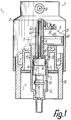
- the discharge device 1 which is essentially assembled from injection-molded plastic parts, is used for essentially sealed placement on the neck of a storage device, from which, with each return stroke, a certain amount of a medium is drawn in by a discharge pipe 3 via a riser pipe. It also has, from the atmosphere, bypassing a thrust piston pump 5 of the discharge unit 3, conveying means 4 for compressed air, which are essentially formed by a thrust piston pump 6 arranged on the same base body 2 in the same axis as the pump 5. Both pumps 5, 6 are essentially simultaneous with a common actuation 7 via a discharge and Actuate actuating head 8 by finger pressure so that a push actuation is transmitted to the pump movement.
- the actuating head 8 has a discharge opening 9 opening into the open, which, influenced by control means 10, is connected to the discharge unit 3 via an outlet channel 11 and via a separate channel which opens near it to the conveyor 4 closer to it.
- a cylinder housing 12 which is formed in one piece with the base body 2 accommodates a piston unit 13 which is formed by two separate pump pistons 14, 15 of the discharge unit 3 which are axially movable relative to one another and constantly mesh with one another.
- the inner circumference of the pump piston 14 projecting in the direction of the pump stroke by about half its length over the other pump piston 15 is assigned an outer circumferential surface as a piston raceway 16.
- the inner circumference of the cylinder housing 12 forms a cylinder raceway 17 for the sealed abutment of the front end of the pump piston 15, which, like the pump piston 14, is cup-shaped, but is considerably shorter.
- An annular gap is formed between the cylinder race 17 and the outer circumference of the front, enlarged section of the pump piston 14 as well as between the inner circumference of the pump piston 15 and the outer circumference of the pump piston 14; the successive annular gaps represent a line connection for the outlet channel 11.
- the cylinder housing 12 forms an inlet, through which the pump 5 draws in from the reservoir through a riser pipe and via which it, controlled by the control means 10, can convey back into the reservoir .
- This inlet forms a substantially completely within the cylinder housing 12 and the cylinder race 17 and essentially in line with these lying inlet and return channel 18, the flow cross section can be changed depending on the stroke.
- the channel 18 is delimited by a sleeve 19 projecting essentially freely and coaxially into the cylinder housing, the outer circumference of which has a radial distance from the cylinder race 17 and forms a control valve 20 with an inner sealing lip 21 at the front end of the pump piston 14.
- the sealing lip 22 running on the piston raceway 17 is located at the front end of the pump piston 15.
- the outer circumference of the sleeve 19 forms a valve seat 23 between the ends and only over a part of its length over which the sealing lip 21 has been passed, for the sealingly displaceable contact of the sealing lip 21.
- the sleeve 19 is on the associated section with a radial against the cylinder track 17 projecting collar 24 provided.
- an obliquely frusto-conical inclined surface 25 At the end of the cylindrical valve seat 23, which was first reached by the sealing lip 21 during the pumping stroke, is followed by an obliquely frusto-conical inclined surface 25, while the other end is delimited by an annular shoulder 26 lying approximately at right angles to the valve seat 23.
- the sections 27, 28 lying adjacent to the collar 24 can have essentially the same outer width, which is approximately constant through to the respective associated end, such that an annular gap is delimited between them and the sealing lip 21.
- the same outside width also has a plug-in section 29 formed by a front end, with which the sleeve 19 is inserted in a tightly adapted manner, narrowed relative to the cylinder race 17 and adjoining it via an annular shoulder, with an opening of the cylinder housing 17 which is limited by a stop.
- the slide or piston 14 forms with the sleeve 19 a throttle 30, the flow cross section of which changes with the position of the pump piston 14 depending on the path.
- the jacket of the pump piston 14 is so narrowed at a distance behind the sealing lip 21 on the inner circumference that with the outer circumference of the section 27 it can limit an annular gap which is narrower than the annular gap in the region of the sealing lip 21.
- a mandrel 31 lies completely inside the pump piston 14, the front end of which is set back relative to the sealing lip 21.
- a pretensioned helical compression spring 32 is fitted snugly on the outer circumference of the mandrel 31 and is provided as the only spring for all resetting functions of the discharge unit 3 and for the pump resetting of the conveying means 4.
- the other end of the spring 32 is supported within the plug section 29 on an annular shoulder and therefore presses the sleeve 19 connected to the riser pipe into its stop position.
- the spring 32 lies with its outer circumference closely on the inner circumference of the channel 18. In the starting position according to FIGS. 1 and 2, the free end 33 of the sleeve 19 lies within the pump piston 14 at a short distance behind the sealing lip 21 and at a short distance from the front end of the mandrel 31.
- the pump piston 14 is moved over a first partial stroke 38 corresponding to this distance, the front end of the mandrel 31 penetrates into the channel 18, so that a helical channel which is essentially closed in cross section over the outer circumference is penetrated by the windings of the spring 32 lying therebetween is limited within the sleeve 19 and then to the end 33, the flow cross section of which can be smaller than that of the annular gap in the region of the sealing lip 21.
- the partial stroke 38 lies at the beginning of a first partial stroke 34, which is required until the sealing lip 21 has reached the beginning of the inclined surface 25.
- the annular gap in the area of the sealing lip 21 becomes continuously narrower until the sealing lip 21 runs onto the inclined surface 25 and thereby the connection between the channel 18 and the annular pump chamber 39 closes.
- the end 33 of the sleeve 19 reaches the narrowed section of the pump piston 14, so that both parts can be brought together and the liquid in the hollow pump piston 14 can be pressed further through the channel 18 back into the reservoir.
- the sealing lip 21 then reaches the cylindrical valve seat 23 under radial prestress, which determines the next subsequent partial stroke 36 and via which a delivery or discharge pressure is now built up in the pump chamber 39.
- the medium can be conveyed from the pump chamber 39 to the outlet channel 11 via the annular gaps mentioned on the outer circumference of the pump piston 14.
- the line connection between the pump chamber 39, which is now substantially constricted, and the channel 18 can be opened again, if necessary throttled, opened or closed, depending on the dimensions selected.
- the line connection is opened here when the outer circumference of section 27 is smaller than the narrowed inner circumference of pump piston 14 because an annular passage gap is then provided.
- the line connection is closed when the outer width of section 27 is approximately the same size as the narrowed inner circumference. Since a right-angled or at most obtuse-angled conical shoulder 26 adjoins the corresponding end of the valve seat 23, the annular gap between the sealing lip 21 is suddenly opened when this end is passed over. From this end, the last partial stroke 37 takes place until the pump piston 14 strikes the end 33 of the sleeve 19 and the sealing lip 21 is still a short distance from the floor or the associated annular shoulder of the pump chamber 39.
- outlet valve 40 which is biased by the spring 32 to the closed position and whose valve parts can be moved against one another on the two pump pistons 14, 15.
- the tapered valve body 44 is formed in one piece with the end wall 42 which closes off the pump piston 14 at the narrowed, cylindrical piston section 41 and projects with its base beyond the outside thereof. The end 33 abuts on the inside of this end wall 42 and the spring 32 is supported.
- the narrower end of the valve body 44 merges in one piece into a shaft 46 which extends over most of the length of the outlet channel 11 and which is mounted by inserting it into a central channel of a piston rod 47 and with it delimits a section of the outlet channel 11 which is annular in cross section.
- the pump piston 14 is thus centered in the starting position only by the valve body 44 relative to the other pump parts and can then be guided on the corresponding partial strokes 35 to 37 by guiding on the inclined surface 25, on the valve seat 23 and / or on the section 27, so that also open outlet valve 40 accurate centering is ensured.
- the outlet valve 40 is adjusted so that it opens against the force of the spring 32 when the sealing lip 21 runs on the valve seat 23, so that the medium is then pumped out of the pump chamber 39 to the discharge opening 9.
- the pump chamber 39 is relieved of pressure by returning it to the channel 18, so that the opening end of the partial stroke 37 acting on the rear end faces of the pump piston 14, because that in the pump chamber 51 of the pump 6 Compressed air continues to flow even after the end of the actuation until a pressure limit value is reached.
- the pump chamber 51 is of a on the base body 2 with a snap connection in the essentially fixed pump piston 48 and a pump cylinder 49, which is formed by the jacket of the actuating head 8.
- the pump piston 48 is penetrated by the outlet channel 11 or by the actuating plunger 47.
- a pressure-dependent output valve 50 is provided, which opens after a first partial stroke and before the partial stroke 36 is reached.
- the discharge device can be inserted and installed from one side of the base body 2, namely from the open side of the cylinder housing 12, by plugging. Since the pump pistons 14, 15 have essentially flat end walls 42, 43 and the valve seat 45 lies approximately in the plane of the inside of the end wall 43, very compact dimensions are also achieved for the piston unit 13.
- the pump pistons 14, 15 have essentially only cylindrical outer and / or inner shapes in the jacket area.
- the pump piston 48 is fastened with a snap connection and forms a closure for the rear mounting opening of the cylinder housing 12.
- the discharge device can also have, in a simple manner behind the sealing lip 22 which is in the starting position, a ventilation 52 for the storage vessel which is fed via the pump chamber 51 and which, at least in the starting position, is tightly closed by a ventilation valve 53.
- a ventilation 52 for the storage vessel which is fed via the pump chamber 51 and which, at least in the starting position, is tightly closed by a ventilation valve 53.
- the end wall 43 of the pump piston 15 forms on its outside a one-piece, conical valve body, which is pressed under the force of the spring 32 against a valve seat, the closing force being transmitted essentially only via the valve parts of the exhaust valve 40 lying against one another.
- the valve seat is expediently formed by a sleeve 54 of the pump piston 48 which engages in the rear, enlarged end of the cylinder housing 12 and is penetrated by the actuating plunger 47, so that it can be made of a relatively soft material.
- the annular ventilation channel leads from the pump chamber 51 between the sleeve 54 and the actuating plunger 47 to the ventilation valve 53 and from there adjacent to the pump piston 15 across the jacket of the cylinder housing 12 into an annular gap which is between the outer periphery of the rear end of the cylinder housing 12 and the inner periphery a flange sleeve 55 of the base body 2 which surrounds this at a radial distance is formed.
- a cap 56 for example a screw and / or plug cap for attaching the discharge device 1 to the bottle neck or the like of the memory.
- the memory can also be flexibly connected to the discharge device.
- the storage space of the storage vessel can be pressurized with the pump 6, so that the stored medium is pressed through the channel 18 into the pump chamber 39 at the beginning of the return stroke of the pump 5 or at least the suction of the medium is supported.
- the control means 10 described result in a pressure build-up that gradually approaches the outlet pressure of the outlet valve 40, so that the opening of the outlet valve 40 is reached very quickly at the beginning of the partial stroke 36.
Landscapes
- Details Of Reciprocating Pumps (AREA)
- Containers And Packaging Bodies Having A Special Means To Remove Contents (AREA)
- Electrical Discharge Machining, Electrochemical Machining, And Combined Machining (AREA)
- Photographic Developing Apparatuses (AREA)
- Air Transport Of Granular Materials (AREA)
- Reciprocating Pumps (AREA)
- Coating Apparatus (AREA)
- Closures For Containers (AREA)
Applications Claiming Priority (2)
| Application Number | Priority Date | Filing Date | Title |
|---|---|---|---|
| DE4035688A DE4035688A1 (de) | 1990-11-09 | 1990-11-09 | Austragvorrichtung fuer medien |
| DE4035688 | 1990-11-09 |
Publications (2)
| Publication Number | Publication Date |
|---|---|
| EP0484773A1 true EP0484773A1 (fr) | 1992-05-13 |
| EP0484773B1 EP0484773B1 (fr) | 1996-08-14 |
Family
ID=6417958
Family Applications (1)
| Application Number | Title | Priority Date | Filing Date |
|---|---|---|---|
| EP91118296A Expired - Lifetime EP0484773B1 (fr) | 1990-11-09 | 1991-10-26 | Distributeur de fluide |
Country Status (6)
| Country | Link |
|---|---|
| US (1) | US5443185A (fr) |
| EP (1) | EP0484773B1 (fr) |
| JP (1) | JP2981327B2 (fr) |
| AT (1) | ATE141190T1 (fr) |
| DE (2) | DE4035688A1 (fr) |
| ES (1) | ES2090206T3 (fr) |
Cited By (2)
| Publication number | Priority date | Publication date | Assignee | Title |
|---|---|---|---|---|
| US5271530A (en) * | 1990-11-07 | 1993-12-21 | Daiwa Can Company | Foam dispensing pump container |
| WO1999059728A1 (fr) * | 1998-05-18 | 1999-11-25 | Calmar-Monturas, S.A. | Pompe de pulverisation |
Families Citing this family (10)
| Publication number | Priority date | Publication date | Assignee | Title |
|---|---|---|---|---|
| DE19711791A1 (de) * | 1997-03-21 | 1998-09-24 | Pfeiffer Erich Gmbh & Co Kg | Austragvorrichtung für Medien |
| DE19723134A1 (de) * | 1997-06-03 | 1998-12-10 | Pfeiffer Erich Gmbh & Co Kg | Austragvorrichtung für Medien |
| DE19756442A1 (de) | 1997-12-18 | 1999-06-24 | Pfeiffer Erich Gmbh & Co Kg | Spender für Medien |
| DE10220557A1 (de) * | 2002-05-02 | 2003-11-13 | Pfeiffer Erich Gmbh & Co Kg | Spender zum Austrag fließfähiger Medien |
| US8257580B2 (en) * | 2004-10-13 | 2012-09-04 | Marathon Oil Canada Corporation | Dry, stackable tailings and methods for producing the same |
| US8101067B2 (en) * | 2004-10-13 | 2012-01-24 | Marathon Oil Canada Corporation | Methods for obtaining bitumen from bituminous materials |
| NL1031092C2 (nl) * | 2006-02-07 | 2007-08-08 | Airspray Nv | Zelfreinigende schuimafgifteinrichting. |
| US8663462B2 (en) * | 2009-09-16 | 2014-03-04 | Shell Canada Energy Cheveron Canada Limited | Methods for obtaining bitumen from bituminous materials |
| US8864982B2 (en) * | 2009-12-28 | 2014-10-21 | Shell Canada Energy Cheveron Canada Limited | Methods for obtaining bitumen from bituminous materials |
| US20110180458A1 (en) * | 2010-01-22 | 2011-07-28 | Marathon Oil Canada Corporation | Methods for extracting bitumen from bituminous material |
Citations (4)
| Publication number | Priority date | Publication date | Assignee | Title |
|---|---|---|---|---|
| FR2407752A2 (fr) * | 1977-11-07 | 1979-06-01 | Step Soc Tech Pulverisation | Perfectionnements apportes aux vaporisateurs |
| GB2023225A (en) * | 1978-06-19 | 1979-12-28 | Aerosol Inventions Dev | Pump for hand-held containers |
| US4189064A (en) * | 1978-06-01 | 1980-02-19 | Diamond International Corporation | Pumps sprayer |
| DE3722469A1 (de) * | 1987-07-08 | 1989-01-19 | Pfeiffer Erich Gmbh & Co Kg | Handbetaetigbare austragvorrichtung fuer medien |
Family Cites Families (11)
| Publication number | Priority date | Publication date | Assignee | Title |
|---|---|---|---|---|
| US4051983B1 (en) * | 1975-11-19 | 1993-12-14 | Calmar Inc. | Pump sprayer having pump priming means |
| US4274560A (en) * | 1976-04-30 | 1981-06-23 | Emson Research Incorporated | Atomizing pump dispenser |
| JPS5815021Y2 (ja) * | 1977-06-02 | 1983-03-25 | 株式会社三谷バルブ | 手動噴霧器の噴射装置 |
| US4173297A (en) * | 1978-01-30 | 1979-11-06 | The Risdon Manufacturing Company | Non-throttling manually reciprocated plunger pump for consumer-type liquid dispensing containers |
| DE3544985A1 (de) * | 1985-12-19 | 1987-06-25 | Pfeiffer Erich Gmbh & Co Kg | Austragvorrichtung fuer fliessfaehige medien |
| DE3715301A1 (de) * | 1987-05-08 | 1988-11-24 | Pfeiffer Erich Gmbh & Co Kg | Austragvorrichtung fuer medien |
| FR2620052B1 (fr) * | 1987-09-09 | 1990-04-27 | Valois | Vaporisateur du type pompe manuelle a precompression pour utilisation avec un gaz propulseur |
| EP0345132B1 (fr) * | 1988-06-02 | 1993-09-22 | Societe Technique De Pulverisation Step | Pompe-doseuse à précompression à amorçage amélioré |
| US5037023A (en) * | 1988-11-28 | 1991-08-06 | Hitachi, Ltd. | Method and apparatus for wire bonding |
| FR2645835B1 (fr) * | 1989-04-14 | 1991-09-06 | Step Soc Tech Pulverisation | Dispositif de securite pour vaporisateur |
| US5020696A (en) * | 1989-11-27 | 1991-06-04 | Rjs Industries, Inc. | Atomizing fluid dispenser two |
-
1990
- 1990-11-09 DE DE4035688A patent/DE4035688A1/de not_active Withdrawn
-
1991
- 1991-10-26 AT AT91118296T patent/ATE141190T1/de not_active IP Right Cessation
- 1991-10-26 EP EP91118296A patent/EP0484773B1/fr not_active Expired - Lifetime
- 1991-10-26 ES ES91118296T patent/ES2090206T3/es not_active Expired - Lifetime
- 1991-10-26 DE DE59108075T patent/DE59108075D1/de not_active Expired - Fee Related
- 1991-11-08 JP JP3319583A patent/JP2981327B2/ja not_active Expired - Fee Related
-
1993
- 1993-11-12 US US08/151,480 patent/US5443185A/en not_active Expired - Lifetime
Patent Citations (4)
| Publication number | Priority date | Publication date | Assignee | Title |
|---|---|---|---|---|
| FR2407752A2 (fr) * | 1977-11-07 | 1979-06-01 | Step Soc Tech Pulverisation | Perfectionnements apportes aux vaporisateurs |
| US4189064A (en) * | 1978-06-01 | 1980-02-19 | Diamond International Corporation | Pumps sprayer |
| GB2023225A (en) * | 1978-06-19 | 1979-12-28 | Aerosol Inventions Dev | Pump for hand-held containers |
| DE3722469A1 (de) * | 1987-07-08 | 1989-01-19 | Pfeiffer Erich Gmbh & Co Kg | Handbetaetigbare austragvorrichtung fuer medien |
Cited By (2)
| Publication number | Priority date | Publication date | Assignee | Title |
|---|---|---|---|---|
| US5271530A (en) * | 1990-11-07 | 1993-12-21 | Daiwa Can Company | Foam dispensing pump container |
| WO1999059728A1 (fr) * | 1998-05-18 | 1999-11-25 | Calmar-Monturas, S.A. | Pompe de pulverisation |
Also Published As
| Publication number | Publication date |
|---|---|
| DE59108075D1 (de) | 1996-09-19 |
| US5443185A (en) | 1995-08-22 |
| ES2090206T3 (es) | 1996-10-16 |
| ATE141190T1 (de) | 1996-08-15 |
| DE4035688A1 (de) | 1992-05-14 |
| JPH0761485A (ja) | 1995-03-07 |
| EP0484773B1 (fr) | 1996-08-14 |
| JP2981327B2 (ja) | 1999-11-22 |
Similar Documents
| Publication | Publication Date | Title |
|---|---|---|
| DE4102506C2 (de) | Austragvorrichtung für Medien | |
| EP0815946B1 (fr) | Distributeur pour fluides | |
| EP0289855B1 (fr) | Distributeur de fluides | |
| EP0199143B1 (fr) | Pompe à piston coulissant pour délivrer des substances fluides | |
| EP0309010B1 (fr) | Distributeur manuel pour fluide | |
| DE10220557A1 (de) | Spender zum Austrag fließfähiger Medien | |
| EP0504748B1 (fr) | Distributeur de fluids | |
| DE4417488A1 (de) | Austragvorrichtung für Medien | |
| EP0184686B1 (fr) | Pompe à piston pour distributeur de substance active | |
| EP0790079A2 (fr) | Distributeur de fluides et procédé de fabrication d'un distributeur ou équivalent | |
| DE3315334A1 (de) | Zerstaeuber- oder dosierpumpe | |
| DE3780906T2 (de) | Pumpe mit einer durchflussmenge, unabhaengig vom betaetigungsdruck. | |
| DE1653419A1 (de) | Fluessigkeitsabgabepumpe | |
| EP0484773B1 (fr) | Distributeur de fluide | |
| EP0505974B1 (fr) | Distributeur de fluides | |
| EP0289854B1 (fr) | Distributeur de fluides | |
| EP0901835B1 (fr) | Distributeur de produit | |
| EP0451615B1 (fr) | Dispositif pour décharger au moins un produit | |
| DE19727356B4 (de) | Spender für Medien | |
| EP0484835B1 (fr) | Distributeur de fluide | |
| EP0032541A2 (fr) | Buse réglable pour pulvérisateur à fonctionnement manuel | |
| EP0992289B1 (fr) | Distributeur de fluides | |
| EP2686112B1 (fr) | Dispositif distributeur | |
| EP0829307A2 (fr) | Distributeur de fluides | |
| EP0505900A1 (fr) | Distributeur de fluides |
Legal Events
| Date | Code | Title | Description |
|---|---|---|---|
| PUAI | Public reference made under article 153(3) epc to a published international application that has entered the european phase |
Free format text: ORIGINAL CODE: 0009012 |
|
| AK | Designated contracting states |
Kind code of ref document: A1 Designated state(s): AT CH DE ES FR GB IT LI SE |
|
| 17P | Request for examination filed |
Effective date: 19920509 |
|
| 17Q | First examination report despatched |
Effective date: 19931124 |
|
| GRAH | Despatch of communication of intention to grant a patent |
Free format text: ORIGINAL CODE: EPIDOS IGRA |
|
| RAP1 | Party data changed (applicant data changed or rights of an application transferred) |
Owner name: ING. ERICH PFEIFFER GMBH |
|
| GRAA | (expected) grant |
Free format text: ORIGINAL CODE: 0009210 |
|
| GRAH | Despatch of communication of intention to grant a patent |
Free format text: ORIGINAL CODE: EPIDOS IGRA |
|
| AK | Designated contracting states |
Kind code of ref document: B1 Designated state(s): AT CH DE ES FR GB IT LI SE |
|
| REF | Corresponds to: |
Ref document number: 141190 Country of ref document: AT Date of ref document: 19960815 Kind code of ref document: T |
|
| REG | Reference to a national code |
Ref country code: CH Ref legal event code: NV Representative=s name: TROESCH SCHEIDEGGER WERNER AG |
|
| REF | Corresponds to: |
Ref document number: 59108075 Country of ref document: DE Date of ref document: 19960919 |
|
| REG | Reference to a national code |
Ref country code: ES Ref legal event code: FG2A Ref document number: 2090206 Country of ref document: ES Kind code of ref document: T3 |
|
| GBT | Gb: translation of ep patent filed (gb section 77(6)(a)/1977) |
Effective date: 19960927 |
|
| ITF | It: translation for a ep patent filed | ||
| REG | Reference to a national code |
Ref country code: ES Ref legal event code: FG2A Ref document number: 2090206 Country of ref document: ES Kind code of ref document: T3 |
|
| ET | Fr: translation filed | ||
| PLBE | No opposition filed within time limit |
Free format text: ORIGINAL CODE: 0009261 |
|
| STAA | Information on the status of an ep patent application or granted ep patent |
Free format text: STATUS: NO OPPOSITION FILED WITHIN TIME LIMIT |
|
| 26N | No opposition filed | ||
| REG | Reference to a national code |
Ref country code: GB Ref legal event code: IF02 |
|
| PGFP | Annual fee paid to national office [announced via postgrant information from national office to epo] |
Ref country code: AT Payment date: 20021022 Year of fee payment: 12 |
|
| PG25 | Lapsed in a contracting state [announced via postgrant information from national office to epo] |
Ref country code: AT Free format text: LAPSE BECAUSE OF NON-PAYMENT OF DUE FEES Effective date: 20031026 |
|
| PGFP | Annual fee paid to national office [announced via postgrant information from national office to epo] |
Ref country code: ES Payment date: 20041026 Year of fee payment: 14 |
|
| PG25 | Lapsed in a contracting state [announced via postgrant information from national office to epo] |
Ref country code: ES Free format text: LAPSE BECAUSE OF NON-PAYMENT OF DUE FEES Effective date: 20051027 |
|
| PGFP | Annual fee paid to national office [announced via postgrant information from national office to epo] |
Ref country code: GB Payment date: 20061024 Year of fee payment: 16 Ref country code: SE Payment date: 20061024 Year of fee payment: 16 |
|
| PGFP | Annual fee paid to national office [announced via postgrant information from national office to epo] |
Ref country code: IT Payment date: 20061031 Year of fee payment: 16 |
|
| REG | Reference to a national code |
Ref country code: ES Ref legal event code: FD2A Effective date: 20051027 |
|
| PGFP | Annual fee paid to national office [announced via postgrant information from national office to epo] |
Ref country code: DE Payment date: 20071025 Year of fee payment: 17 |
|
| PGFP | Annual fee paid to national office [announced via postgrant information from national office to epo] |
Ref country code: CH Payment date: 20071023 Year of fee payment: 17 |
|
| PGFP | Annual fee paid to national office [announced via postgrant information from national office to epo] |
Ref country code: FR Payment date: 20071019 Year of fee payment: 17 |
|
| EUG | Se: european patent has lapsed | ||
| GBPC | Gb: european patent ceased through non-payment of renewal fee |
Effective date: 20071026 |
|
| PG25 | Lapsed in a contracting state [announced via postgrant information from national office to epo] |
Ref country code: SE Free format text: LAPSE BECAUSE OF NON-PAYMENT OF DUE FEES Effective date: 20071027 |
|
| PG25 | Lapsed in a contracting state [announced via postgrant information from national office to epo] |
Ref country code: GB Free format text: LAPSE BECAUSE OF NON-PAYMENT OF DUE FEES Effective date: 20071026 |
|
| REG | Reference to a national code |
Ref country code: CH Ref legal event code: PL |
|
| REG | Reference to a national code |
Ref country code: FR Ref legal event code: ST Effective date: 20090630 |
|
| PG25 | Lapsed in a contracting state [announced via postgrant information from national office to epo] |
Ref country code: IT Free format text: LAPSE BECAUSE OF NON-PAYMENT OF DUE FEES Effective date: 20071026 Ref country code: DE Free format text: LAPSE BECAUSE OF NON-PAYMENT OF DUE FEES Effective date: 20090501 |
|
| PG25 | Lapsed in a contracting state [announced via postgrant information from national office to epo] |
Ref country code: CH Free format text: LAPSE BECAUSE OF NON-PAYMENT OF DUE FEES Effective date: 20081031 Ref country code: FR Free format text: LAPSE BECAUSE OF NON-PAYMENT OF DUE FEES Effective date: 20081031 Ref country code: LI Free format text: LAPSE BECAUSE OF NON-PAYMENT OF DUE FEES Effective date: 20081031 |