EP0484838A1 - Chaudière pour combustibles liquides ou gazeux - Google Patents
Chaudière pour combustibles liquides ou gazeux Download PDFInfo
- Publication number
- EP0484838A1 EP0484838A1 EP91118689A EP91118689A EP0484838A1 EP 0484838 A1 EP0484838 A1 EP 0484838A1 EP 91118689 A EP91118689 A EP 91118689A EP 91118689 A EP91118689 A EP 91118689A EP 0484838 A1 EP0484838 A1 EP 0484838A1
- Authority
- EP
- European Patent Office
- Prior art keywords
- sealing ring
- combustion chamber
- web
- boiler
- water
- Prior art date
- Legal status (The legal status is an assumption and is not a legal conclusion. Google has not performed a legal analysis and makes no representation as to the accuracy of the status listed.)
- Withdrawn
Links
- 239000000446 fuel Substances 0.000 title claims abstract description 4
- 239000007788 liquid Substances 0.000 title claims abstract description 4
- 238000007789 sealing Methods 0.000 claims abstract description 23
- 238000002485 combustion reaction Methods 0.000 claims abstract description 16
- XLYOFNOQVPJJNP-UHFFFAOYSA-N water Substances O XLYOFNOQVPJJNP-UHFFFAOYSA-N 0.000 claims abstract description 7
- 229910001018 Cast iron Inorganic materials 0.000 claims abstract description 5
- 238000006073 displacement reaction Methods 0.000 claims abstract description 3
- 238000010276 construction Methods 0.000 description 2
- 238000011161 development Methods 0.000 description 2
- 230000018109 developmental process Effects 0.000 description 2
- UGFAIRIUMAVXCW-UHFFFAOYSA-N Carbon monoxide Chemical compound [O+]#[C-] UGFAIRIUMAVXCW-UHFFFAOYSA-N 0.000 description 1
- 229910000831 Steel Inorganic materials 0.000 description 1
- 238000010304 firing Methods 0.000 description 1
- 239000003546 flue gas Substances 0.000 description 1
- 239000007789 gas Substances 0.000 description 1
- 238000010438 heat treatment Methods 0.000 description 1
- 239000010959 steel Substances 0.000 description 1
Images
Classifications
-
- F—MECHANICAL ENGINEERING; LIGHTING; HEATING; WEAPONS; BLASTING
- F24—HEATING; RANGES; VENTILATING
- F24H—FLUID HEATERS, e.g. WATER OR AIR HEATERS, HAVING HEAT-GENERATING MEANS, e.g. HEAT PUMPS, IN GENERAL
- F24H1/00—Water heaters, e.g. boilers, continuous-flow heaters or water-storage heaters
- F24H1/22—Water heaters other than continuous-flow or water-storage heaters, e.g. water heaters for central heating
- F24H1/24—Water heaters other than continuous-flow or water-storage heaters, e.g. water heaters for central heating with water mantle surrounding the combustion chamber or chambers
- F24H1/26—Water heaters other than continuous-flow or water-storage heaters, e.g. water heaters for central heating with water mantle surrounding the combustion chamber or chambers the water mantle forming an integral body
- F24H1/263—Water heaters other than continuous-flow or water-storage heaters, e.g. water heaters for central heating with water mantle surrounding the combustion chamber or chambers the water mantle forming an integral body with a dry-wall combustion chamber
-
- F—MECHANICAL ENGINEERING; LIGHTING; HEATING; WEAPONS; BLASTING
- F24—HEATING; RANGES; VENTILATING
- F24H—FLUID HEATERS, e.g. WATER OR AIR HEATERS, HAVING HEAT-GENERATING MEANS, e.g. HEAT PUMPS, IN GENERAL
- F24H9/00—Details
- F24H9/14—Arrangements for connecting different sections, e.g. in water heaters
-
- F—MECHANICAL ENGINEERING; LIGHTING; HEATING; WEAPONS; BLASTING
- F24—HEATING; RANGES; VENTILATING
- F24H—FLUID HEATERS, e.g. WATER OR AIR HEATERS, HAVING HEAT-GENERATING MEANS, e.g. HEAT PUMPS, IN GENERAL
- F24H9/00—Details
- F24H9/14—Arrangements for connecting different sections, e.g. in water heaters
- F24H9/146—Connecting elements of a heat exchanger
-
- F—MECHANICAL ENGINEERING; LIGHTING; HEATING; WEAPONS; BLASTING
- F24—HEATING; RANGES; VENTILATING
- F24H—FLUID HEATERS, e.g. WATER OR AIR HEATERS, HAVING HEAT-GENERATING MEANS, e.g. HEAT PUMPS, IN GENERAL
- F24H1/00—Water heaters, e.g. boilers, continuous-flow heaters or water-storage heaters
- F24H1/22—Water heaters other than continuous-flow or water-storage heaters, e.g. water heaters for central heating
- F24H1/24—Water heaters other than continuous-flow or water-storage heaters, e.g. water heaters for central heating with water mantle surrounding the combustion chamber or chambers
- F24H1/30—Water heaters other than continuous-flow or water-storage heaters, e.g. water heaters for central heating with water mantle surrounding the combustion chamber or chambers the water mantle being built up from sections
- F24H1/32—Water heaters other than continuous-flow or water-storage heaters, e.g. water heaters for central heating with water mantle surrounding the combustion chamber or chambers the water mantle being built up from sections with vertical sections arranged side by side
Definitions
- the invention relates to a boiler for burning liquid or gaseous fuels according to the preamble of the main claim.
- Boilers of the type mentioned are known from EP-A-0 414 926 and are used in different, but in principle identical construction forms.
- this well-known boiler design applies both to sheet steel and cast iron boilers, the cast iron boilers being made from relatively narrow, one-piece and core-cast individual members (see DE-A-20 17 992 and also FR-A-22 37 141) exist, which, nippled in the area of relatively small overflow openings on the water side, are joined to form a block consisting of a large number of individual members.
- a boiler design according to FR-A-1 084 896 also has a similar link construction, according to which the links are sealed to one another with O-ring seals.
- the abutting surfaces of one or the other link are equipped with ring grooves for receiving the O-rings. It may be left open whether this sealing arrangement and design actually meets the sealing requirements, but in any case it can be the different thermal expansions in the walls, namely in the wall, which on the one hand the combustion chamber to the water-bearing interior and the wall that the water-bearing Interior space limited on the other hand, not enough, and the invention has for its object to provide such a boiler, a sealing system that better suits the different expansion conditions at the different temperatures exposed walls.
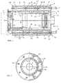
- the boiler consists of a water-carrying housing 3, provided with supply and return connections 1, 2, which is penetrated by a combustion chamber 4, the two openings 5 of which are provided with closures 6, 7, one of which 6 is the insert opening 8 for the burner and the other 7 contains the exhaust system.
- the water-carrying housing 3 is formed from two middle members 10 and two end members 11, 12, the corelessly shaped members 10 to 12 being directed towards one another and sealed together with their opening edges 13.
- the firing chamber 4 is the limit in each case
- Wall 14 is formed as a web 15 encircling the links, which ends as an integrally molded part in the connecting plane E of the link in question, the transverse wall 16 of the boiler members 10 supporting the web 15 being provided with a plurality of openings 18 connecting all the interior 17 of the members.
- these openings 17 are very large in relation to the total cross section of a link, ie the sum of all cross sections 17 corresponds practically to the total cross section of a link in the water-carrying area.
- 1 is a horizontal boiler with a pot-shaped combustion chamber 20 inserted in the combustion chamber 4.
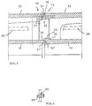
- the two central links 10 are H-shaped in cross section, while the two end links 11, 12 Are U-shaped, the end member 11 has an annular collar 11 'for the connection of the burner 9 carrying the combustion chamber closure and the end member 12 has a flue-side rear wall with a cast-on flue gas outlet connection 21. All the members are designed in the region of their opening edges 13 such that all the connecting edges 13 'have interlocking steps 30, in which areas seals are arranged, which is explained in more detail in relation to FIG. 3.
- the tension connection of the links to one another is achieved by the fact that all the links 10, 11, 12 are tensioned with tension rods 28 which are evenly distributed over the circumference of the housing and which span the links in their openings 18 Cross walls 16 pass through much smaller openings 29 sealed.
- tension rods 28 Such an end of the tension rods, which are shown in their distribution over the entire circumference in FIG. 2, is illustrated in FIG. 4.
- This arrangement of the tension rods 28 in the passage of the water-carrying interior advantageously ensures that both the outwardly sealing ring seals 31 and the ring seals 31 'lying on the combustion chamber side can be clamped together at the same time.
- the coreless formability of the links 10 to 12 also makes it possible for the water-side to be distributed evenly over the circumference in the links the respective link outer wall 33 and the wall 14 delimiting the firebox 4, stiffening ribs 34 can be arranged, which end in front of the opening edges 13.
- the shape of the ribs 34 is illustrated in FIG. 1 and their arrangement with respect to the boiler cross section in FIG. 2.
- a sealing ring 31 ' is clamped between the two surfaces 32, 32' of the webs 15, which extend perpendicular to the longitudinal axis of the combustion chamber, in the joint regions between the opening edges 13 of two members 10 to 12, and a further sealing ring 31 is arranged in one end or the other 35, secured against axial displacement, between the ends 35 of the outer link walls 33 which overlap in the axial direction.
- a flat ring seal is particularly suitable, as shown, and an O-ring seal for the sealing ring 31.
- the surface 32 extends at one end of the web 15 in one plane, and the surface 32 'at the other end of the web 15 is delimited towards the water side by an annular collar 36 which overlaps the other end of the adjacent link.
- a collar 36 can also be provided on the combustion chamber side, as indicated by dashed lines, in order to shield the sealing ring 31 'against the direct exposure to heating gases.
- a sealing ring receiving groove 37 is provided in one or the other of the overlapping ends 35 of the link outer walls 33.
- at least one of the overlapping ends 35 is advantageously provided with a slip-on chamfer 38 in order to facilitate the joining of the links without risk of damage to the sealing rings 31.
Landscapes
- Engineering & Computer Science (AREA)
- Physics & Mathematics (AREA)
- Thermal Sciences (AREA)
- Chemical & Material Sciences (AREA)
- Combustion & Propulsion (AREA)
- Mechanical Engineering (AREA)
- General Engineering & Computer Science (AREA)
- Combustion Of Fluid Fuel (AREA)
- Details Of Fluid Heaters (AREA)
Applications Claiming Priority (2)
| Application Number | Priority Date | Filing Date | Title |
|---|---|---|---|
| DE4035138 | 1990-11-06 | ||
| DE19904035138 DE4035138A1 (de) | 1990-11-06 | 1990-11-06 | Heizkessel zum verbrennen fluessiger oder gasfoermiger brennstoffe |
Publications (1)
| Publication Number | Publication Date |
|---|---|
| EP0484838A1 true EP0484838A1 (fr) | 1992-05-13 |
Family
ID=6417666
Family Applications (1)
| Application Number | Title | Priority Date | Filing Date |
|---|---|---|---|
| EP91118689A Withdrawn EP0484838A1 (fr) | 1990-11-06 | 1991-11-02 | Chaudière pour combustibles liquides ou gazeux |
Country Status (2)
| Country | Link |
|---|---|
| EP (1) | EP0484838A1 (fr) |
| DE (1) | DE4035138A1 (fr) |
Cited By (1)
| Publication number | Priority date | Publication date | Assignee | Title |
|---|---|---|---|---|
| EP1098148A3 (fr) * | 1999-11-08 | 2003-01-22 | Joh. Vaillant GmbH u. Co. | Chaudière |
Families Citing this family (2)
| Publication number | Priority date | Publication date | Assignee | Title |
|---|---|---|---|---|
| DE4216649C2 (de) * | 1992-05-20 | 1994-08-25 | Buderus Heiztechnik Gmbh | Dichtschnur |
| EP0601253B1 (fr) * | 1992-12-07 | 1995-07-19 | De Dietrich Thermique | Perfectionnement aux chaudières en fonte |
Citations (4)
| Publication number | Priority date | Publication date | Assignee | Title |
|---|---|---|---|---|
| DE1911593A1 (de) * | 1969-03-07 | 1970-12-03 | Buderus Eisenwerk | Gliederkessel |
| FR2449254A1 (fr) * | 1979-02-19 | 1980-09-12 | Viessmann Hans | Chaudiere pour combustibles liquides ou gazeux |
| CH670148A5 (fr) * | 1985-07-02 | 1989-05-12 | Viessmann Hans | |
| EP0414925A1 (fr) * | 1989-08-28 | 1991-03-06 | Hans Dr. Viessmann | Chaudière pour brûler des combustibles fluides ou gazeux |
Family Cites Families (2)
| Publication number | Priority date | Publication date | Assignee | Title |
|---|---|---|---|---|
| FR1084869A (fr) * | 1952-10-10 | 1955-01-25 | Husqvarna Vapenfabriks Ab | Chaudière de chauffage |
| DE1299392B (de) * | 1966-10-06 | 1969-07-17 | Alfred Konrad Maschf | Gliederheizkessel |
-
1990
- 1990-11-06 DE DE19904035138 patent/DE4035138A1/de not_active Withdrawn
-
1991
- 1991-11-02 EP EP91118689A patent/EP0484838A1/fr not_active Withdrawn
Patent Citations (4)
| Publication number | Priority date | Publication date | Assignee | Title |
|---|---|---|---|---|
| DE1911593A1 (de) * | 1969-03-07 | 1970-12-03 | Buderus Eisenwerk | Gliederkessel |
| FR2449254A1 (fr) * | 1979-02-19 | 1980-09-12 | Viessmann Hans | Chaudiere pour combustibles liquides ou gazeux |
| CH670148A5 (fr) * | 1985-07-02 | 1989-05-12 | Viessmann Hans | |
| EP0414925A1 (fr) * | 1989-08-28 | 1991-03-06 | Hans Dr. Viessmann | Chaudière pour brûler des combustibles fluides ou gazeux |
Cited By (1)
| Publication number | Priority date | Publication date | Assignee | Title |
|---|---|---|---|---|
| EP1098148A3 (fr) * | 1999-11-08 | 2003-01-22 | Joh. Vaillant GmbH u. Co. | Chaudière |
Also Published As
| Publication number | Publication date |
|---|---|
| DE4035138A1 (de) | 1992-05-07 |
Similar Documents
| Publication | Publication Date | Title |
|---|---|---|
| DE3143394C2 (de) | Wandaufbau für die Brennkammer eines Gasturbinentriebwerks | |
| EP0735251A1 (fr) | Collecteur d'échappement pour un moteur à combustion interne | |
| EP0484838A1 (fr) | Chaudière pour combustibles liquides ou gazeux | |
| WO1991006813A1 (fr) | Chaudiere pour combustibles liquides ou gazeux | |
| DE2945994A1 (de) | Waermetauscher fuer industrielle kuehlzwecke zum kuehlen von luft u.a. gasen | |
| EP0414925B1 (fr) | Chaudière pour brûler des combustibles fluides ou gazeux | |
| EP0120435B1 (fr) | Structure du parcours du gaz de chauffage dans une chaudière de chauffage | |
| DE2948864C2 (de) | Heizungskessel für die Verbrennung von flüssigen oder gasförmigen Brennstoffen | |
| EP2314916B1 (fr) | Ensemble de grille de combustion | |
| DE19502765C2 (de) | Heizkessel in Gliederbauweise | |
| DE1953565A1 (de) | Zerlegbarer Heizkessel fuer eine Wasserzentralheizungsanlage | |
| DE1981985U (de) | Heizkessel fuer fluessige oder gasfoermige brennstoffe. | |
| DE9007764U1 (de) | Heizkessel zum Verbrennen flüssiger oder gasförmiger Brennstoffe | |
| DE2856338B2 (de) | Heizungskessel für flüssige oder gasförmige Brennstoffe | |
| EP0430061B1 (fr) | Chaudière de chauffage | |
| DE29510374U1 (de) | Brennerstab für einen Gasbrenner | |
| EP0387627A2 (fr) | Chaudière | |
| DE9308701U1 (de) | Heizkessel | |
| DE3212349C2 (de) | Niedertemperatur-Heizungskessel | |
| DE2025472C3 (de) | Heizungskessel | |
| DE1925944U (de) | Heizkessel fuer gas, oel oder feste brennstoffe. | |
| DE2160791B2 (de) | Dichtungsanordnung für einen Gliederheizkessel | |
| DE8610463U1 (de) | Heizkessel | |
| DE3307598A1 (de) | Bauelement zur fertigung einer heizungsanlage und unter verwendung solcher bauelemente gefertigte heinzunganlage | |
| EP0640801A1 (fr) | Brûleur atmosphérique à gaz |
Legal Events
| Date | Code | Title | Description |
|---|---|---|---|
| PUAI | Public reference made under article 153(3) epc to a published international application that has entered the european phase |
Free format text: ORIGINAL CODE: 0009012 |
|
| AK | Designated contracting states |
Kind code of ref document: A1 Designated state(s): AT BE CH DE ES FR GB IT LI NL SE |
|
| 17P | Request for examination filed |
Effective date: 19920708 |
|
| 17Q | First examination report despatched |
Effective date: 19931216 |
|
| STAA | Information on the status of an ep patent application or granted ep patent |
Free format text: STATUS: THE APPLICATION IS DEEMED TO BE WITHDRAWN |
|
| 18D | Application deemed to be withdrawn |
Effective date: 19940427 |