EP0484862A2 - Einrichtung zur geschützten Kommunikation und System zur geschützten Übertragung - Google Patents
Einrichtung zur geschützten Kommunikation und System zur geschützten Übertragung Download PDFInfo
- Publication number
- EP0484862A2 EP0484862A2 EP91118788A EP91118788A EP0484862A2 EP 0484862 A2 EP0484862 A2 EP 0484862A2 EP 91118788 A EP91118788 A EP 91118788A EP 91118788 A EP91118788 A EP 91118788A EP 0484862 A2 EP0484862 A2 EP 0484862A2
- Authority
- EP
- European Patent Office
- Prior art keywords
- signal
- communication equipment
- information
- random pattern
- random
- Prior art date
- Legal status (The legal status is an assumption and is not a legal conclusion. Google has not performed a legal analysis and makes no representation as to the accuracy of the status listed.)
- Granted
Links
Images


Classifications
-
- H—ELECTRICITY
- H04—ELECTRIC COMMUNICATION TECHNIQUE
- H04L—TRANSMISSION OF DIGITAL INFORMATION, e.g. TELEGRAPHIC COMMUNICATION
- H04L9/00—Cryptographic mechanisms or cryptographic arrangements for secret or secure communications; Network security protocols
- H04L9/06—Cryptographic mechanisms or cryptographic arrangements for secret or secure communications; Network security protocols the encryption apparatus using shift registers or memories for block-wise or stream coding, e.g. DES systems or RC4; Hash functions; Pseudorandom sequence generators
- H04L9/065—Encryption by serially and continuously modifying data stream elements, e.g. stream cipher systems, RC4, SEAL or A5/3
- H04L9/0656—Pseudorandom key sequence combined element-for-element with data sequence, e.g. one-time-pad [OTP] or Vernam's cipher
-
- H—ELECTRICITY
- H04—ELECTRIC COMMUNICATION TECHNIQUE
- H04L—TRANSMISSION OF DIGITAL INFORMATION, e.g. TELEGRAPHIC COMMUNICATION
- H04L2209/00—Additional information or applications relating to cryptographic mechanisms or cryptographic arrangements for secret or secure communication H04L9/00
- H04L2209/12—Details relating to cryptographic hardware or logic circuitry
-
- H—ELECTRICITY
- H04—ELECTRIC COMMUNICATION TECHNIQUE
- H04L—TRANSMISSION OF DIGITAL INFORMATION, e.g. TELEGRAPHIC COMMUNICATION
- H04L2209/00—Additional information or applications relating to cryptographic mechanisms or cryptographic arrangements for secret or secure communication H04L9/00
- H04L2209/34—Encoding or coding, e.g. Huffman coding or error correction
-
- Y—GENERAL TAGGING OF NEW TECHNOLOGICAL DEVELOPMENTS; GENERAL TAGGING OF CROSS-SECTIONAL TECHNOLOGIES SPANNING OVER SEVERAL SECTIONS OF THE IPC; TECHNICAL SUBJECTS COVERED BY FORMER USPC CROSS-REFERENCE ART COLLECTIONS [XRACs] AND DIGESTS
- Y04—INFORMATION OR COMMUNICATION TECHNOLOGIES HAVING AN IMPACT ON OTHER TECHNOLOGY AREAS
- Y04S—SYSTEMS INTEGRATING TECHNOLOGIES RELATED TO POWER NETWORK OPERATION, COMMUNICATION OR INFORMATION TECHNOLOGIES FOR IMPROVING THE ELECTRICAL POWER GENERATION, TRANSMISSION, DISTRIBUTION, MANAGEMENT OR USAGE, i.e. SMART GRIDS
- Y04S40/00—Systems for electrical power generation, transmission, distribution or end-user application management characterised by the use of communication or information technologies, or communication or information technology specific aspects supporting them
- Y04S40/20—Information technology specific aspects, e.g. CAD, simulation, modelling, system security
Definitions
- the present invention relates to a secure transmission system in which a plurality of pieces of secure communication equipment perform secure communication between them over a transmission line.
- the invention also pertains to such secure communication equipment.
- an information signal A to be transmitted is encrypted by a scrambling circuit 11A and is then provided onto the transmission line 10L from a transmitting circuit 12A.
- the scrambling circuit 11A encrypts the information signal A, using a fixed random pattern K1 (an encrypting key) which is available from a pseudo random pattern generator 15A.
- the encrypted signal A' is transmitted by the transmitting circuit 12A to the communication equipment 100B over the transmission line 10L.
- a signal B' received by a receiving circuit 13A from the communication equipment 100B through the transmission line 10L is decoded by a descrambling circuit 14A using a fixed random pattern K2 (decoding key) available from a pseudo random pattern generator 16A, whereby an information signal B from the communication equipment 100B is obtained.
- Another object of the present invention is to provide a secure communication system which is simple in construction but ensures great security of the transmission of information.
- the secure communication equipment of the present invention includes: converting means for generating an encrypted signal by performing a logical conversion of a signal to be transmitted, through use of a signal received from the called party; transmitting circuit means for providing the encrypted signal onto a transmission line; information storage means for storing, as key information, a signal corresponding to the transmitted signal; receiving circuit means for receiving an encrypted signal transmitted over the transmission line; and inverse conversion means for outputting a signal obtained by decoding the received encrypted signal through its inverse logical conversion by use of the key information read out of the information storage means.
- the secure transmission system have at least first and second pieces of communication equipment interconnected via a transmission line.
- the first communication equipment includes: first receiving circuit means for receiving a signal from the second communication equipment; converting means for generating an encrypted signal by performing a logical conversion of a signal to be transmitted, through use of the received signal; and first transmitting circuit means for providing the encrypted signal onto the transmission line.
- the second communication equipment includes: information storage means for storing, as key information, a signal to be transmitted; second transmitting circuit means for providing the signal to be transmitted onto the transmission line; second receiving circuit means for receiving an encrypted signal transmitted over the transmission line; and inverse conversion means for outputting a signal obtained by decoding the received encrypted signal through its inverse logical conversion by use of the key information read out of the information storage means.
- transmission signals are encrypted using successively changing received signals from the called party, and consequently, it is very difficult for an outsider to decode the encrypted transmission signals.
- the encryption of transmission signals through utilization of received signals permit implementation of high security even by a relatively simple logical conversion. Accordingly, the communication equipment can be manufactured relatively small in scale and at a low cost.
- Fig. 2 illustrates in block form an embodiment of the secure transmission system in which the two pieces of secure communication equipment 100A and 100B embodying the present invention are connected to the transmission line 10L. Three or more pieces of secure communication equipment may also be connected to the transmission line, and since they are identical in construction, the communication equipment 100A will hereinafter be described.
- the secure communication equipment 100A is made up of a transmitting circuit 12A, a receiving circuit 13A, a conversion part 17A, an inverse conversion part 18A and a transmitting information memory 23A.
- the conversion part 17A may be an exclusive OR circuit which obtains the exclusive OR of a received information signal B and a transmission information signal A, or similar simple logical circuit.
- the same is true of the inverse conversion part 18A.
- the transmission information signal A of a predetermined length is applied to the conversion part 17A, wherein it is encrypted by logical conversion through utilization of the latest decoded information signal B.
- the information signal A is provided as key information to the information memory 23A and is stored therein until decoding of an encrypted information signal B' received next.
- the thus encrypted signal A' is transmitted by the transmitting circuit 12A to the other secure communication equipment 100B over the transmission line 10L.
- a received encrypted signal B' supplied via the transmission line 10L from the secure communication equipment 100B to the receiving circuit 13A is provided to the inverse conversion part 18A, wherein it is decoded into the information signal B by the key information signal A read out of the information memory 23A.
- the information signal A to be transmitted next is applied as new key information to the information memory 23A, wherein its content is rewritten, and at the same time, the information signal A is also applied to the conversion part 17A.
- the signal A' thus encrypted using the information signal B can be decoded in the secure communication equipment 100B, using a key information signal B stored in an information memory 23B, and the signal B' encrypted using the decoded information signal A in the secure communication equipment 100B can be decoded in the secure communication equipment 100A through utilization of the information signal A stored in the information memory 23A. Since the information signals A and B are ever-changing, however, it is hard to decode the encrypted signals A' and B' in communication equipment where neither of the information signals A and B are available.
- the exclusive OR of the initial value B0: 00000000 of the key information stored in the memory 23B and the received signal A1' i.e.
- the transmission information A is subjected to the logical conversion in the scrambling circuit 11A by a fixed random pattern K1 from the pseudo random pattern generator 15A as in the case of Fig. 1 and is then subjected to processing for transmission similar to that in Fig. 2 and the received information signal output from the inverse conversion part 18A is subjected to inverse logical conversion in the descrambling circuit 14A by a fixed random pattern K2 from the pseudo random pattern generator 16A.
- the scrambling circuit 11A and the descrambling circuit 14A may be formed by exclusive OR circuits or some other logical circuits, for example.
- the scrambling circuit 11A is intended primarily for randomizing the transmission information signal A, not for encryption. Accordingly, if the initial value of the key information is set to a predetermined value except all zeros and all ones and if there is guarantee that the transmission information signal A will not be a sequence of zeros or ones, no scrambling is needed. Conversely, security can be enhanced by scrambling. Moreover, by using different patterns of the same length as the scrambling patterns (the pseudo random patterns) which are used by the communication equipment 100A and the other side communication equipment 100B (not shown in Fig. 4), security improves accordingly; further, by making the lengths (the numbers of bits) of the patterns different, security will be further enhanced.
- an external synchronization system for establishing synchronization between, for example, the phase of the pseudo random pattern K1 for the information signal A in the scrambling circuit 11A of the secure communication equipment 100A and the phase of the pseudo random pattern K1 for the received encrypted signal A' in the descrambling circuit 14B of the secure communication equipment 100B.
- a known self-synchronization type scrambling circuit in which an information signal input for each bit is applied to, for example, the one input terminal of an exclusive OR circuit, the output of the exclusive OR circuit is fed back to the other input thereof via a predetermined number of stages of shift registers and the output of the exclusive OR circuit is used as the output of the scrambling circuit.
- a self-synchronization type descrambling circuit for use with such a self-synchronization type scrambling circuit is also well-known.
- the conversion part 17A may also be formed by a random pattern generator and a logical conversion circuit so as to further enhance the security.
- Fig. 5 shows an example of the secure communication equipment 100A in such an instance.
- a random pattern generator 21A of the conversion part 17A creates and outputs a random pattern corresponding to all or a predetermined number of bits of the decoded information signal B.
- a logical conversion circuit 22A may be an exclusive OR circuit or similar logical circuit as mentioned above.
- the inverse conversion part 18A may also be formed by a random pattern generator 24A and an inverse logical conversion circuit 25A.
- the random pattern generator 24A of the inverse conversion part 18A need not always be exactly identical in construction with the random pattern generator 21A of the conversion part 17A. The same is true of the secure communication equipment 100B, but it is necessary that random pattern generators of the conversion part 17B and the inverse conversion part 18B (not shown) be exactly identical in construction with the random pattern generators 24A and 21A of the inverse conversion part 18A and the conversion part 17A, respectively.
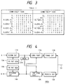
- Fig. 6 illustrates an embodiment of the random pattern generators 21A and 24A in Fig. 5 (and those of the conversion part 17A and the inverse conversion part 18B), which is made up of a division circuit 31 and a non-linear operation circuit 32.
- the division circuit 31 divides the information signal A or B or its one part by a predetermined polynomial and provides the residue (see W. W. Peterson and E. J. Weldon, "Error-correcting codes," M.I.T. Press, 1972, for example) to the non-linear operation circuit 32.
- the non-linear operation circuit 32 is a circuit which performs an irreversible calculation which is hard to estimate the input from the output thereof, and the calculated output is provided as a random pattern.
- Fig. 7 shows an example of such a non-linear operation circuit 32 which is formed by a recursive filter.
- the non-linear operation circuit 32 has its initial value set corresponding to the residue provided from the division circuit 31 and generates a random pattern from the initial value.
- the non-linear operation circuit 32 is made up of, for example, 8-bit D type flip-flop circuits 41 and 42 forming two stages of parallel 8-bit shift registers (i.e. two stages of delay circuits), a bit shifter 43 and an eight-bit adder 44.
- the 8-bit initial values which are set in the 8-bit D type flip-flop circuits 41 and 42, respectively, may be the same data of predetermined eight bits of the residue provided from the division circuit 31, but in the embodiment of Fig.
- the 8-bit data is set in the flip-flop circuit 41 and the logic of all the eight bits of the 8-bit data is inverted by a logical inverting circuit 45, then the inverted output is set in the flip-flop circuit 42.
- the 8-bit data set in the flip-flop circuit 41 is provided to the bit shifter 43, wherein its all bits are shifted, for instance, in the direction of the least significant bit a predetermined number of bits, for example, one bit (that is, the 8-bit data is divided by 2) and the underflow is discarded, and at the same time, the resultant 8-bit output is applied to the one input of the 8-bit adder 44.
- the adder 44 is supplied at the other input with the contents of the eight bits set in the flip-flop circuit 42.
- the overflow resulting from the addition is discarded and the 8-bit added output is provided as a partial pattern in a random pattern sequence and, at the same time, it is applied to a data terminal D (8-bit) of the flip-flop circuit 41.
- a clock signal CK is applied to clock terminals CK of the flip-flop circuits 41 and 42 in the above state, the 8-bit Q output of the flip-flop 41 is fetched into the flip-flop circuit 42, and at the same time, data provided to the data terminal D of the flip-flop circuit 41 is fetched thereinto, in consequence of which the next partial pattern (8-bit) is output from the adder 44.
- the clock signal CK is applied to the flip-flop circuits 41 and 42 every eight bits of the information signal A (or B).
- the bit shifter 43 may also shift the input 8-bit data in the direction of the most significant bit, a predetermined number of bits (i.e. multiplied by a power of 2) and discard the overflow.
- the irreversibility of calculation can be achieved by discarding the overflow of the adder 44 or the underflow (or overflow) of the divider (or multiplier) 43 as mentioned above.
- a random pattern is produced as a sequence of partial patterns which are uniquely determined in accordance with the input information signal A (or B), and it is very difficult to estimate the information signal A (or B) from such a series of partial patterns. It is evident that the security could be further enhanced by raising the order of the recursive filter 32.
- Fig. 8 illustrates another embodiment of the random pattern generator 21A or 24A (similar circuit being provided in the communication equipment 100B, too), which is comprised of a logical operation circuit 33, an identification number memory 34, a decoder 35, a fixed pattern memory 36 and a change-over switch 37.
- the identification number memory 34 has stored therein an identification number ID assigned to the secure communication equipment concerned.
- the logical operation circuit 33 performs a logical calculation or operation of the applied information signal A (or B) and the identification number ID from the identification memory 34 or its predetermined part and outputs the result of the operation as a random pattern RP via the change-over switch 37.
- the decoder 35 When having detected that the input information signal A (or B) is all zeros or all ones, the decoder 35 outputs a control signal, by which the change-over switch 37 is connected to the fixed pattern memory 36 to output therefrom a predetermined fixed pattern other than those of all zeros and all ones.
- the change-over switch 37 need not always be provided at the output of the logical calculation circuit 33 but may also be provided at the output side of the logical conversion circuit 22A (the inverse logical conversion circuit 25A).
- Fig. 9 illustrates still another embodiment of the random pattern generator 21A or 24A.
- This embodiment selectively outputs one of a plurality of, for instance, eight different random patterns in accordance with the input information signal A (or B), and this circuit has such a construction as described below.
- a timer circuit 51 is supplied with the clock signal CK regenerated by the receiving circuit 13A and a frame synchronizing signal FSYN and is reset by the latter and counts the former and, when the count value has reached a predetermined value, it applies a time-up signal TU to a load terminal L of a selector 53.
- the frame synchronizing signal FSYN is also applied to a reset terminal R of an octernary counter 52 via the timer circuit 51.
- the octernary counter 52 is supplied with the information signal A (or B) and sequentially counts "1's" (or "0's") in a sequence of its bits.
- the selector 53 fetches therein the count value of the octernary counter 52, selects one of eight random pattern generators R1 through R8 in accordance with the count value and outputs a random pattern RP generated by the selected random pattern generator.
- the random pattern generators R1 through R8 may be well-known pseudo random pattern generators each formed by, for instance, a shift register and exclusive OR circuits, or they may also be constituted by a ROM having stored therein a required number (eight in this example) of random patterns or software of a programmed random pattern generating procedure.
- Fig. 10 illustrates another embodiment of the secure communication equipment 100A which employs such random pattern generators as exemplified above and is constructed with a view to making it more difficult to decode the input information signal from the generated random pattern.
- This embodiment differs from the secure communication equipment of Fig. 2 in that pattern degenerating circuits 26A and 27A are provided at the input sides of the random pattern generators 21A and 24A in the conversion part 17A and the inverse conversion part 18A, respectively.
- the pattern degenerating circuits 26A and 27A are each supplied with 2 n possible different patterns (n-bit) and allot a predetermined one of M different patterns smaller in number than 2 n to each of the input patterns, and consequently, the same output pattern is produced for a plurality of different input patterns.
- the random pattern generator 21A also outputs the same random pattern. It is impossible to judge, from the random pattern output from the random pattern generator 21A, which of the two patterns the received information signal B corresponds to.
- the random pattern generator 21A and the pattern degenerating circuit 26A may also be exchanged in position, and similarly, the random pattern generator 24A and the pattern degenerating circuit 27A may also be exchanged in position.
- Fig. 11 illustrates an embodiment of the pattern degenerating circuit 26A (or 27A) used in the embodiment of Fig. 10.
- the illustrated example comprises a two-stage shift register 46, an AND circuit 47 and another two-stage shift register 48.
- outputs Q1 and Q2 of its two stages are provided via input terminals X1 and X2 to input terminals of the AND circuit 47 and their logical product is provided to an output terminal Y1.
- the output Q2 is provided via the input terminal X2 to an output terminal Y2 as well.
- Fig. 13 illustrates another embodiment of each secure communication equipment in the Fig. 2 embodiment.
- the following description will be given of the equipment 100A.
- an error detector 28A for detecting a code error in the received encrypted signal B' output from the receiving circuit 13A.
- random patterns created by the random pattern generators 21A and 24A are fetched into pattern memories 38A and 39A, from which they are provided to the conversion circuit 22A and the inverse conversion circuit 25A.
- the error detector 28A utilizes, for example, a well-known CRC (cyclic redundancy check) error detecting method and, upon detecting a code error in the received encrypted signal B', it applies a detection signal Ea to an inhibit terminal INH of the pattern memory 38A and the transmitting circuit 12A.
- CRC cyclic redundancy check
- the pattern memory 38A is inhibited by the detection signal Ea from fetching the random pattern from the random pattern generator 21A, and consequently, the random pattern held until then is not updated and is supplied again to the logical conversion circuit 22A.
- the logical conversion circuit 22A uses the random pattern to encrypt the information signal A and the transmitting circuit 12A appends the error detection signal Ea to the head of the encrypted information signal A' and then provides the signal onto the transmission line 10L. As long as the error detector 28A outputs the error detection signal Ea (one bit), this operation is repeated, and when the error detector 28A stops from outputting the error detection signal Ea, the pattern memory 38A resumes fetching thereinto of the random pattern from the random pattern generator 21A.
- the communication equipment 100B of the called party has detected a code error in the received encrypted signal A', the same operation as described above is performed, and as a result, the encrypted information signal B' appended with an error detection signal Eb is transmitted to the communication equipment 100A. Having detected the error detection signal Eb appended to the received encrypted signal B', the receiving circuit 13A of the communication equipment 100A inhibits, by the signal Eb, the random pattern fetching operation of the pattern memory 38A of the inverse conversion part 18A. Hence, the received encrypted signal B' is decoded by the inverse logical conversion circuit 25A through use of the random pattern held in the pattern memory 39A until then.
- the random pattern that is produced by the random pattern generator 21A based on the received information signal B containing the error, is not used but a random pattern created immediately before is used to encrypt the information signal A and the error detection signal Ea is transmitted to the called communication equipment 100B, so that correct decoding and encrypting processing can be continued.
- the error detection signals Ea and Eb it is also possible to transmit them a plurality of times and judge an error signal by majority at the receiving side.
- Figs. 5, 10 and 13 have been described in connection with the case where the random pattern for encrypting the information signal A is created by the random pattern generator 21A through utilization of the decoded information signal B and the random pattern for decoding the received encrypted signal B' is produced by the random pattern generator 24A through utilization of the information signal A prior to its encryption, it is also possible to produce the random pattern for encrypting the information signal A through utilization of the received signal B' prior to its decoding and produce the random pattern for decoding the received signal B' through utilization of the encrypted information signal A'.
- Fig. 14 illustrates, corresponding to Fig. 5, an example of the secure communication equipment 100A in such a case. The principles of operation of the communication equipment 100A is the same as in the case of Fig. 5, and hence the description will be omitted.
- the communication equipment 100A performs multiplex communication with plural, for example, two pieces of communication equipment 100B and 100C via the transmission line 10L.
- the multiplex method may be a time division multiplex, frequency multiplex, or similar multiplex method.
- the communication equipment 100A will hereinafter be referred to as center equipment and the pieces of communication equipment 100B and 100C as subscriber equipment.
- the center equipment 100A encrypts information signals A1 and A2 to be transmitted to the pieces of subscriber equipment 100B and 100C by conversion parts 17A1 and 17A2 through use of pieces of decoded information B and C available from the pieces of subscriber equipment 100B and 100C.
- the information signals A1 and A2 are held as key information in information memories 23A1 and 23A2 as in the aforementioned embodiments.
- the encrypted information signals A1' and A2' are multiplexed by a multiplexing circuit 54, thereafter being provided onto the transmission line 10L by the transmitting circuit 12A.
- the subscriber equipment 100B separates, by a demultiplexing circuit 55B, the encrypted information signal A1' destined for the equipment 100B from the multiplexed signal received by the receiving circuit 13B from the center equipment 100A and then decodes the information signal A1' in the inverse conversion part 18B by use of the key information stored in the information memory 23B, that is, the information signal B transmitted immediately before, thus obtaining the information signal A1. Moreover, the subscriber equipment 100B stores the information signal B to be transmitted next in an information memory 23B, encrypts the signal B in the conversion part 17B through use of the decoded information signal A1 and provides the encrypted information signal B' onto the transmission line 10L from the transmitting circuit 12B.
- the signal B' is provided onto the transmission line 10L in a time slot assigned to the subscriber equipment 100B; when an asynchronous time division multiplex system is employed, a packet appended with an address is utilized; and when a frequency multiplex system is employed, a frequency assigned to the equipment 100B is used.
- the subscriber equipment 100C also performs the same operation as mentioned above, whereby it obtains the decoded information signal A2 and transmits an information signal C.
- the center equipment 100A separates, by a demultiplexing circuit 55A, the multiplexed signal received by the receiving circuit 13A to obtain the encrypted information signals B' and C' from the pieces of subscriber equipment 100B and 100C and decodes them in inverse conversion parts 18A1 and 18A2 by use of the pieces of key information A1 and A2 stored in the information memories 23A1 and 23A2, thus obtaining the information signals B and C.
- the random pattern generators depicted in Figs. 6, 8 and 9 and various other random pattern generators are applicable to the conversion parts 17A1, 17A2, 17B, 17C and the inverse conversion parts 18A1, 18A2, 18B, 18C of the pieces of communication equipment 100A, 100B and 100C in the secure transmission system of Fig. 15. It is also possible to adopt an arrangement which employ the scrambling circuit 11A, the descrambling circuit 14A and the pseudo random pattern generators 15A and 16A in each of the pieces of communication equipment 100A, 100B and 100C as depicted in Fig.
- each communication equipment may also have such a construction as shown in Fig. 10, in which information signals are converted by the pattern degenerating circuits 26A and 27A so that their plural different partial patterns may become the same partial pattern, followed by the formation of random patterns based thereon. Also it is possible to utilize such an arrangement as described previously with respect to Fig.
- the transmission line 10L is not limited specifically to an electric signal cable but may also be a spatial radio wave propagation path or optical fiber transmission line.
- Fig. 16 illustrates another embodiment of the present invention in which an optical fiber transmission system is applied to the point to multipoint transmission system shown in Fig. 15.
- To the common optical fiber transmission line 10L from the center equipment 100A are connected, by an optical directional splitter 57, individual optical fiber lines La and Lb from the pieces of subscriber equipment 100B and 100C.
- the multiplexed signal from the center equipment 100A is transmitted to all the pieces of subscriber equipment 100B and 100C at the same time as in the case of Fig. 15.
- each subscriber equipment is capable of easily extracting signals transmitted to the other subscriber equipment, and consequently, it is necessary to encrypt the signals which are transmitted from the center equipment 100A to the pieces of subscriber equipment 100B and 100C.
- each subscriber equipment is connected via the optical directional splitter 57 to the optical fiber transmission line 10L, the transmission signal from each subscriber equipment can be transmitted to only the center equipment 100C without leakage to any other pieces of subscriber equipment. For this reason, in the embodiment of Fig. 16 the transmission signals from the pieces of subscriber equipment 100B and 100C are not encrypted.
- the center equipment 100A does not include the inverse conversion parts 18A1, 18A2 and the information memories 23A1, 23A2 used in the embodiment of Fig. 15.
- the multiplexed signal received by the optical receiving circuit 13A is separated by the demultiplexing circuit 55A into the information signals B and C from the pieces of subscriber equipment 100B and 100C, and in the conversion parts 17A1 and 17A2 the information signals A1 and A2 to be transmitted are encrypted using the information signals B and C.
- the encrypted information signals A1' and A2' are multiplexed by the multiplexing circuit 54 and then provided onto the optical fiber transmission line 10L via an optical coupler 56A from the optical transmitting circuit 12A.
- the transmission signal is branched by the optical directional splitter 57 to all the pieces of subscriber equipment 100B and 100C.
- the pieces of subscriber equipment 100B and 100C do not include the conversion parts 17B and 17C used in the embodiment of Fig. 15.
- the encrypted signal A1' destined therefor is separated by the demultiplexing circuit 55B from the multiplexed signal received by the optical receiving circuit 13B and is then provided to the inverse conversion part 18B, wherein it is decoded into the information signal A1 through utilization of the key information stored in the information memory 23B, i.e. the immediately preceding transmitted information signal B.
- the information signal B to be transmitted from the subscriber equipment 100B is not encrypted and is provided intact onto the optical fiber transmission line 10L from the optical transmitting circuit 12B via an optical coupler 56B and the optical directional splitter 57.
- the conversion parts 17A1, 17A2 and the inverse conversion parts 18B, 18C may each be implemented by a simple exclusive OR circuit, and it is also possible, with a view to further increasing security, to form the conversion parts 17A1 and 17A2 by the random pattern generator 21A and the logical conversion circuit 22A and the inverse conversion parts 18B and 18C by the random pattern generator 24A and the inverse logical conversion circuit 25A as in the case of the Fig. 5 embodiment.
- the afore-mentioned various embodiments can be used as the random pattern generators.
- the center equipment 100A usually possesses a function of controlling the entire transmission system and has the polynomial or the identification number ID that each subscriber equipment uses in the random pattern generator in Fig. 6 or 8.
- the center equipment 100A may also be constructed so that the information signals A1 and A2 are preencrypted by fixed patterns in scrambling circuits at the input sides of the conversion parts 17A1 and 17A2 and that the received information signals demultiplexed by the demultiplexing circuit 55A are decoded by descrambling circuits into the information signals B and C.
- the pieces of subscriber equipment 100B and 100C are also provided with descrambling circuits at the output sides of the inverse conversion parts 18B and 18C and scrambling circuits at the transmission information signal input sides for encrypting the information signals B and C prior to their transmission.
- the embodiment of Fig. 16 may also utilize the pattern degenerating circuits 26A and 27A described previously in respect of Fig. 10.
- the embodiment of Fig. 13 may also be applicable to Fig. 16. That is, the conversion parts 17A1 and 17A2 of the center equipment 100A are each formed to have the same construction as that of the conversion part 17A depicted in Fig. 13 and an error detector is connected to each output of the demultiplexing circuit 55A.
- the error detection outputs of the error detectors are provided as inhibit signals to pattern memories of the corresponding conversion parts and the multiplexing circuit 54, and at the time of multiplexing the encrypted information signals A1' and A2', codes (one bit) representing the error detection signals are appended to the corresponding encrypted information signals at, for example, the head thereof.
- the inverse conversion parts 18B, 18C have the same construction as that of the inverse conversion part 18A depicted in Fig. 13, code error detectors are connected to the outputs of the demultiplexing circuits 55B and 55C, respectively, and the detection outputs are provided as inhibit signals to pattern memories of the inverse conversion parts 18B and 18C.
- Fig. 17 is a timing chart showing the case where upward signals from the pieces of subscriber equipment 100B and 100C to the center equipment 100A and downward signals from the latter to the former are subjected to time division multiplexing with synchronized timing for transmission and reception as in the TDMA, and in this instance the signal transmission and reception period (i.e. the repetitive period) Tf is constant.
- Encrypted signals A11 and A21 (of a constant length) destined for the pieces of subscriber equipment 100B and 100C are transmitted from the center equipment 100A in time slots preassigned to them.
- the pieces of subscriber equipment 100B and 100C extract the encrypted signals A11 and A21 from the time slots assigned to them, respectively, decode the encrypted signals A11 and A21 using the immediately preceding transmission information (not shown) and, after a certain elapsed time Tx, send out information signals B1 and C1.
- the center equipment 100A receives the information signals B1 and C1, encrypts information signals A12 and A22 to be transmitted next through utilization of the received information signals B1 and C1 and, the certain time Tx after the previous transmission, transmits the encrypted information signals A12 and A22 in the predetermined time slots.
- the pieces of subscriber equipment 100B and 100C receive the encrypted information signals A12 and A22 and decode them using the previously transmitted information signals B1 and C1 and, after the certain elapsed time Tx, transmit information signals B2 and C2, respectively. Thereafter, the same operations as mentioned above are repeated.
- Fig. 18 is a signal transmission and reception timing chart of a time division multiplex system of asynchronous signal transmission and reception timing.
- the center equipment 100A has a function of retaining the latest decoded received information from each subscriber equipment until at least the next decoded received signal is obtained, and the center equipment 100A transmits, as packets at arbitrary timing, to the pieces of subscriber equipment 100B and 100C encrypted informations signals appended at the head with their addresses.
- the pieces of subscriber equipment 100B and 100C transmit, at arbitrary timing, packets having their addresses appended to the heads of the information signals B and C to be transmitted, respectively.
- the center equipment 100A and the pieces of subscriber equipment 100B and 100C all have a signal collision detecting function, and in the case of a signal collision being detected during transmission of a signal, the packet is transmitted again.
- Fig. 19 is a timing chart showing an example of a transmission system for transmitting upward and downward signals over different optical fiber lines or at different wavelengths.
- This transmission system has its feature in that the center equipment 100A is capable of successively transmitting signals A11, Al2, ..., and A21, A22, ... to the pieces of subscriber equipment on a time division multiplexed basis in the time slots preassigned to them and at the same time is capable of successively receiving transmitted signals B1, B2, ... and C1, C2, ... from the pieces of subscriber equipment 100B and 100C on a time division multiplexed basis.
- the secure communication equipment has a construction in which the information signal to be transmitted is encrypted by a conversion part through utilization of a decoded received signal or received encrypted signal and is transmitted, the transmission information signal or the encrypted information signal is stored as a key information signal in an information memory until a response information signal from the called party is received, and the received encrypted signal is decoded in an inverse conversion part through utilization of the key information read out of the information memory. Since the pieces of information for encrypting and decoding use are successively changing, it is possible to realize secure communication equipment which permit highly secure communication.
- the secure transmission system according to the present invention which has at least two pieces of communication equipment are interconnected via a transmission line has a construction in which a first piece of communication equipment transmits an information signal to the second piece of communication equipment after encrypting it in a conversion part through utilization of the previously received signal and the second communication equipment decodes the received encrypted information signal in an inverse conversion part through utilization of a key information signal which is the immediately preceding key information stored in the information memory. Since the received signals for encrypting use are successively changing, it is possible to obtain a highly secure transmission system.
Landscapes
- Engineering & Computer Science (AREA)
- Computer Security & Cryptography (AREA)
- Computer Networks & Wireless Communication (AREA)
- Signal Processing (AREA)
- Mobile Radio Communication Systems (AREA)
- Detection And Prevention Of Errors In Transmission (AREA)
Applications Claiming Priority (2)
| Application Number | Priority Date | Filing Date | Title |
|---|---|---|---|
| JP29949290 | 1990-11-05 | ||
| JP299492/90 | 1990-11-05 |
Publications (3)
| Publication Number | Publication Date |
|---|---|
| EP0484862A2 true EP0484862A2 (de) | 1992-05-13 |
| EP0484862A3 EP0484862A3 (en) | 1993-03-10 |
| EP0484862B1 EP0484862B1 (de) | 1997-04-16 |
Family
ID=17873274
Family Applications (1)
| Application Number | Title | Priority Date | Filing Date |
|---|---|---|---|
| EP91118788A Expired - Lifetime EP0484862B1 (de) | 1990-11-05 | 1991-11-04 | Einrichtung zur geschützten Kommunikation und System zur geschützten Übertragung |
Country Status (3)
| Country | Link |
|---|---|
| US (1) | US5204903A (de) |
| EP (1) | EP0484862B1 (de) |
| DE (1) | DE69125685T2 (de) |
Families Citing this family (18)
| Publication number | Priority date | Publication date | Assignee | Title |
|---|---|---|---|---|
| US5825887A (en) * | 1995-12-28 | 1998-10-20 | Trimble Navigation Limited | Transmitting and receiving apparatus for full code correlation operation under encryption for satellite positioning system |
| US6408019B1 (en) | 1997-12-29 | 2002-06-18 | Georgia Tech Research Corporation | System and method for communication using noise |
| US6192477B1 (en) * | 1999-02-02 | 2001-02-20 | Dagg Llc | Methods, software, and apparatus for secure communication over a computer network |
| JP2002208923A (ja) | 2001-01-11 | 2002-07-26 | Oki Electric Ind Co Ltd | 間欠信号の暗号化伝送システム |
| US7120255B2 (en) | 2002-04-04 | 2006-10-10 | International Business Machines Corporation | Java applications for secured palm held cellular communications |
| US8352726B2 (en) * | 2003-11-07 | 2013-01-08 | Netapp, Inc. | Data storage and/or retrieval |
| US8090857B2 (en) | 2003-11-24 | 2012-01-03 | Qualcomm Atheros, Inc. | Medium access control layer that encapsulates data from a plurality of received data units into a plurality of independently transmittable blocks |
| US7512237B1 (en) | 2004-10-26 | 2009-03-31 | Lockheed Martin Corporation | Encryption for optical communications using dynamic subcarrier multiplexing |
| CN101151070B (zh) * | 2005-03-11 | 2011-08-03 | 普洛浦有限公司 | 吊带型安全带 |
| US8509442B2 (en) * | 2005-07-27 | 2013-08-13 | Sharp Laboratories Of America, Inc. | Association, authentication, and security in a network |
| US20070058659A1 (en) * | 2005-07-27 | 2007-03-15 | Ayyagari Deepak V | Method for providing requested quality of service |
| US8027345B2 (en) * | 2005-07-27 | 2011-09-27 | Sharp Laboratories Of America, Inc. | Method for automatically providing quality of service |
| US7848306B2 (en) * | 2005-07-27 | 2010-12-07 | Sharp Laboratories Of America, Inc. | Coexistence of access provider and in-home networks |
| US8175190B2 (en) | 2005-07-27 | 2012-05-08 | Qualcomm Atheros, Inc. | Managing spectra of modulated signals in a communication network |
| US7856008B2 (en) | 2005-07-27 | 2010-12-21 | Sharp Laboratories Of America, Inc. | Synchronizing channel sharing with neighboring networks |
| US7720471B2 (en) * | 2005-07-27 | 2010-05-18 | Sharp Laboratories Of America | Method for managing hidden stations in a centrally controlled network |
| US7966262B2 (en) * | 2006-10-31 | 2011-06-21 | Radiant Systems, Inc. | Pay at pump encryption device |
| US11552781B2 (en) | 2019-04-05 | 2023-01-10 | Honeywell International Inc. | Using error detection bits for cryptographic integrity and authentication |
Family Cites Families (5)
| Publication number | Priority date | Publication date | Assignee | Title |
|---|---|---|---|---|
| US4663500A (en) * | 1982-02-22 | 1987-05-05 | Nec Corporation | Cryptographic system |
| US4805216A (en) * | 1987-01-08 | 1989-02-14 | Compfax Corporation | Method and apparatus for continuously acknowledged link encrypting |
| FR2640449B1 (fr) * | 1988-12-14 | 1991-05-31 | Abiven Jacques | Procede et systemes de communication a cryptage de l'information |
| US4926478A (en) * | 1988-12-30 | 1990-05-15 | Gruenberg Elliot | Method and apparatus for continuously acknowledged link encrypting |
| US5008938A (en) * | 1990-03-09 | 1991-04-16 | Motorola, Inc. | Encryption apparatus |
-
1991
- 1991-11-04 DE DE69125685T patent/DE69125685T2/de not_active Expired - Lifetime
- 1991-11-04 EP EP91118788A patent/EP0484862B1/de not_active Expired - Lifetime
- 1991-11-05 US US07/786,799 patent/US5204903A/en not_active Expired - Lifetime
Also Published As
| Publication number | Publication date |
|---|---|
| DE69125685D1 (de) | 1997-05-22 |
| EP0484862A3 (en) | 1993-03-10 |
| US5204903A (en) | 1993-04-20 |
| DE69125685T2 (de) | 1997-09-18 |
| EP0484862B1 (de) | 1997-04-16 |
Similar Documents
| Publication | Publication Date | Title |
|---|---|---|
| US5204903A (en) | Secure communication equipment and secure transmission system | |
| EP0227318B1 (de) | Verschlüsselungs-/Entschlüsselungssystem | |
| US5844923A (en) | Fast framing of nude ATM by header error check | |
| EP0320882B1 (de) | Demultiplexeranordnung | |
| US4208650A (en) | Data transmission system | |
| NL8020502A (de) | ||
| US4689606A (en) | Data encoding/decoding circuit | |
| JPH04284753A (ja) | Crc演算方法及びatm交換方式におけるhec同期装置 | |
| US6914984B2 (en) | Encryption apparatus using data encryption standard algorithm | |
| JP2538524B2 (ja) | 信号復号方法および装置 | |
| US4431865A (en) | Digital signal enciphering and deciphering apparatus and system | |
| DK170266B1 (da) | Chifreringssystem og fremgangsmåde til chifrering og dechifrering | |
| US4899339A (en) | Digital multiplexer | |
| US4698813A (en) | Arrangement for correcting burst errors in shortened cyclical block codes | |
| JPH04211543A (ja) | ディジタルデータ秘匿装置 | |
| EP0105553B1 (de) | Einrichtung zur Verschlüsselung digitaler Signale welche eine oder mehrere DES-Schaltungen enthält | |
| EP0818900B1 (de) | Digitale Multiplex-Vorrichtung | |
| EP0370291B1 (de) | System und Anordnung zur Übertragung von aus Datenblöcken bestehenden Signalen | |
| US4543559A (en) | Generator of encoding or decoding 8-bit bytes which can be used in a video system | |
| US5280484A (en) | Time-division multiplex communication system with a synchronizing circuit at the receiving end which responds to the coding of words inserted in the transmitted information | |
| JP3008965B2 (ja) | 暗号化通信装置及び暗号化伝送システム | |
| JPH06342257A (ja) | 逐次暗号方式 | |
| JP2967748B2 (ja) | Atmセル同期回路 | |
| JP2952051B2 (ja) | Atmにおけるセル同期演算回路 | |
| RU10965U1 (ru) | Приемопередатчик дуплексной системы связи |
Legal Events
| Date | Code | Title | Description |
|---|---|---|---|
| PUAI | Public reference made under article 153(3) epc to a published international application that has entered the european phase |
Free format text: ORIGINAL CODE: 0009012 |
|
| 17P | Request for examination filed |
Effective date: 19911104 |
|
| AK | Designated contracting states |
Kind code of ref document: A2 Designated state(s): DE FR GB |
|
| PUAL | Search report despatched |
Free format text: ORIGINAL CODE: 0009013 |
|
| AK | Designated contracting states |
Kind code of ref document: A3 Designated state(s): DE FR GB |
|
| 17Q | First examination report despatched |
Effective date: 19960105 |
|
| RAP1 | Party data changed (applicant data changed or rights of an application transferred) |
Owner name: NIPPON TELEGRAPH AND TELEPHONE CORPORATION |
|
| GRAG | Despatch of communication of intention to grant |
Free format text: ORIGINAL CODE: EPIDOS AGRA |
|
| GRAH | Despatch of communication of intention to grant a patent |
Free format text: ORIGINAL CODE: EPIDOS IGRA |
|
| GRAH | Despatch of communication of intention to grant a patent |
Free format text: ORIGINAL CODE: EPIDOS IGRA |
|
| GRAA | (expected) grant |
Free format text: ORIGINAL CODE: 0009210 |
|
| AK | Designated contracting states |
Kind code of ref document: B1 Designated state(s): DE FR GB |
|
| REF | Corresponds to: |
Ref document number: 69125685 Country of ref document: DE Date of ref document: 19970522 |
|
| ET | Fr: translation filed | ||
| PLBE | No opposition filed within time limit |
Free format text: ORIGINAL CODE: 0009261 |
|
| STAA | Information on the status of an ep patent application or granted ep patent |
Free format text: STATUS: NO OPPOSITION FILED WITHIN TIME LIMIT |
|
| 26N | No opposition filed | ||
| REG | Reference to a national code |
Ref country code: GB Ref legal event code: IF02 |
|
| PGFP | Annual fee paid to national office [announced via postgrant information from national office to epo] |
Ref country code: FR Payment date: 20101026 Year of fee payment: 20 |
|
| PGFP | Annual fee paid to national office [announced via postgrant information from national office to epo] |
Ref country code: DE Payment date: 20101126 Year of fee payment: 20 |
|
| PGFP | Annual fee paid to national office [announced via postgrant information from national office to epo] |
Ref country code: GB Payment date: 20101103 Year of fee payment: 20 |
|
| REG | Reference to a national code |
Ref country code: DE Ref legal event code: R071 Ref document number: 69125685 Country of ref document: DE |
|
| REG | Reference to a national code |
Ref country code: DE Ref legal event code: R071 Ref document number: 69125685 Country of ref document: DE |
|
| REG | Reference to a national code |
Ref country code: GB Ref legal event code: PE20 Expiry date: 20111103 |
|
| PG25 | Lapsed in a contracting state [announced via postgrant information from national office to epo] |
Ref country code: GB Free format text: LAPSE BECAUSE OF EXPIRATION OF PROTECTION Effective date: 20111103 |
|
| PG25 | Lapsed in a contracting state [announced via postgrant information from national office to epo] |
Ref country code: DE Free format text: LAPSE BECAUSE OF EXPIRATION OF PROTECTION Effective date: 20111105 |