EP0484892A1 - Elément-isolateur à ceinture dans l'ancrage des mâts de radio - Google Patents
Elément-isolateur à ceinture dans l'ancrage des mâts de radio Download PDFInfo
- Publication number
- EP0484892A1 EP0484892A1 EP91118883A EP91118883A EP0484892A1 EP 0484892 A1 EP0484892 A1 EP 0484892A1 EP 91118883 A EP91118883 A EP 91118883A EP 91118883 A EP91118883 A EP 91118883A EP 0484892 A1 EP0484892 A1 EP 0484892A1
- Authority
- EP
- European Patent Office
- Prior art keywords
- insulator
- bracket
- webbing
- isolator
- steel segment
- Prior art date
- Legal status (The legal status is an assumption and is not a legal conclusion. Google has not performed a legal analysis and makes no representation as to the accuracy of the status listed.)
- Granted
Links
Images
Classifications
-
- H—ELECTRICITY
- H01—ELECTRIC ELEMENTS
- H01Q—ANTENNAS, i.e. RADIO AERIALS
- H01Q1/00—Details of, or arrangements associated with, antennas
- H01Q1/12—Supports; Mounting means
- H01Q1/1242—Rigid masts specially adapted for supporting an aerial
Definitions
- the invention relates to a webbing isolator element in the guying of radio masts with at least one isolator, which is encompassed on two opposite sides by an isolator bracket, at the free ends of which connecting elements are articulated to the adjacent isolator element or an end element.
- the insulator bracket is fork-shaped at each end, a web-shaped steel segment being welded to an inner and outer bracket bracket, the inner bracket bracket forming the contact surface for the actual insulator.
- the manufacture of such insulator brackets is very complex, which applies in the same way if such an insulator bracket is manufactured in one piece as a drop forging.
- the cross bolt has an unfavorable load in the threaded part which is at risk from notching. In any case, this has proven to be the weakest part in breaking attempts.
- the object of the invention is to provide a solution which both enables a simpler and less expensive production and also avoids the unfavorable loads described above.
- the isolator bracket consists of a steel segment with a turned-out contact surface for the isolator, around which a bracket tab is welded, at the ends of which tabs are connected on both sides as connecting elements with the adjacent one Attack insulator element or end element.
- the steel segment at the ends of its welding zones is provided with the bracket flap with a bulge directed essentially towards the bracket flap, in particular if this bulge is circular in the middle.
- threaded bores can be formed at the ends of the turned-out contact surfaces of the steel segment for fastening rounded mounting brackets for the insulator.
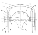
- a steel segment 1 is formed with a turned-out contact surface 1 a for the actual insulator 7 and is welded on its outer edge to a bracket tab 2, with partially circular bulges 12 being provided at the ends of its welding zones with the bracket tab.
- bracket tab 2 At each end of the bracket tab 2, two connecting tabs 8 engage, each of which forms a connecting element to the adjacent insulator element or end element.
- the design is such that a connecting bolt 4 passing through both lugs 8 of the connecting element and one end of the bracket lug 2 is held with an outer fixed counter flange 9 by a connecting bolt 5 penetrating the latter, which can be screwed into an internal thread of an inner loose counter flange 6.
- the turned steel segment 1 is kept so short that because of the elimination of the previous inner bracket flap threaded holes 10 can be formed at the ends of the turned-out contact surfaces, by means of which rounded mounting brackets 3 for the insulator 7 can be attached by means of a fastening screw 11.
Landscapes
- Connection Of Plates (AREA)
- Insulators (AREA)
Applications Claiming Priority (2)
| Application Number | Priority Date | Filing Date | Title |
|---|---|---|---|
| DE9015351U DE9015351U1 (de) | 1990-11-08 | 1990-11-08 | Gurtband-Isolatorelement in der Abspannung von Funkmasten |
| DE9015351U | 1990-11-08 |
Publications (2)
| Publication Number | Publication Date |
|---|---|
| EP0484892A1 true EP0484892A1 (fr) | 1992-05-13 |
| EP0484892B1 EP0484892B1 (fr) | 1995-07-19 |
Family
ID=6859173
Family Applications (1)
| Application Number | Title | Priority Date | Filing Date |
|---|---|---|---|
| EP91118883A Expired - Lifetime EP0484892B1 (fr) | 1990-11-08 | 1991-11-06 | Elément-isolateur à ceinture dans l'ancrage des mâts de radio |
Country Status (2)
| Country | Link |
|---|---|
| EP (1) | EP0484892B1 (fr) |
| DE (2) | DE9015351U1 (fr) |
Citations (2)
| Publication number | Priority date | Publication date | Assignee | Title |
|---|---|---|---|---|
| US1759253A (en) * | 1929-01-11 | 1930-05-20 | Roy C Gerhardt | Insulator |
| US1937964A (en) * | 1932-04-06 | 1933-12-05 | Lapp Insulator Company Inc | Insulator support for tower or mast type antenne |
-
1990
- 1990-11-08 DE DE9015351U patent/DE9015351U1/de not_active Expired - Lifetime
-
1991
- 1991-11-06 DE DE59106026T patent/DE59106026D1/de not_active Expired - Fee Related
- 1991-11-06 EP EP91118883A patent/EP0484892B1/fr not_active Expired - Lifetime
Patent Citations (2)
| Publication number | Priority date | Publication date | Assignee | Title |
|---|---|---|---|---|
| US1759253A (en) * | 1929-01-11 | 1930-05-20 | Roy C Gerhardt | Insulator |
| US1937964A (en) * | 1932-04-06 | 1933-12-05 | Lapp Insulator Company Inc | Insulator support for tower or mast type antenne |
Also Published As
| Publication number | Publication date |
|---|---|
| DE9015351U1 (de) | 1991-01-17 |
| EP0484892B1 (fr) | 1995-07-19 |
| DE59106026D1 (de) | 1995-08-24 |
Similar Documents
| Publication | Publication Date | Title |
|---|---|---|
| DE8813513U1 (de) | Mutter mit Druckring | |
| DD255766A5 (de) | Demontierbares verbindungsteil | |
| DE69423658T2 (de) | Anschlussblock | |
| DE69203933T2 (de) | Lagerbüchse und Befestigungsschelle für Universalgelenk. | |
| DE3609628A1 (de) | Befestigungselementanordnung | |
| EP0367755B1 (fr) | Dispositif d'entraînement | |
| EP2044341A1 (fr) | Écrou de blocage | |
| DE3225855A1 (de) | Schutzleiter-reihenklemme | |
| EP0484892A1 (fr) | Elément-isolateur à ceinture dans l'ancrage des mâts de radio | |
| WO1998044770A1 (fr) | Dispositif pour fixer un couvercle de blindage | |
| CH664239A5 (de) | Entlastungskonstruktion fuer leitungen von elektrischen geraeten. | |
| EP0017024B1 (fr) | Borne de connexion | |
| DE2833815A1 (de) | Klammerschrauben-verbindungselement | |
| DE3143951A1 (de) | "kombinierte dreh- und verschiebesicherung fuer einen bolzen" | |
| DE2225556C3 (de) | Zweigeteilter, auf einen Mikrowellenhohlleiter aufsteckbarer Hohlleiterflansch | |
| DE69602065T2 (de) | Verbindungsklemme für elektrisches Gerät | |
| DE3532770C2 (fr) | ||
| DE3538067C2 (fr) | ||
| DD280649A1 (de) | Anordnung zur befestigung einer bildroehre in einem gehaeuse | |
| DD221883A1 (de) | Spannstueck | |
| DE3340780C2 (fr) | ||
| DE8329901U1 (de) | Doppel-Zurrauge | |
| DE3332854A1 (de) | Kernreaktorbrennelement | |
| DE9300098U1 (de) | Antennenhaltevorrichtung | |
| EP0567733A1 (fr) | Compensateur |
Legal Events
| Date | Code | Title | Description |
|---|---|---|---|
| PUAI | Public reference made under article 153(3) epc to a published international application that has entered the european phase |
Free format text: ORIGINAL CODE: 0009012 |
|
| AK | Designated contracting states |
Kind code of ref document: A1 Designated state(s): AT BE CH DE DK ES FR GB GR IT LI LU NL SE |
|
| 17P | Request for examination filed |
Effective date: 19921015 |
|
| 17Q | First examination report despatched |
Effective date: 19940805 |
|
| RBV | Designated contracting states (corrected) |
Designated state(s): DE |
|
| GRAA | (expected) grant |
Free format text: ORIGINAL CODE: 0009210 |
|
| AK | Designated contracting states |
Kind code of ref document: B1 Designated state(s): DE |
|
| REF | Corresponds to: |
Ref document number: 59106026 Country of ref document: DE Date of ref document: 19950824 |
|
| PLBE | No opposition filed within time limit |
Free format text: ORIGINAL CODE: 0009261 |
|
| STAA | Information on the status of an ep patent application or granted ep patent |
Free format text: STATUS: NO OPPOSITION FILED WITHIN TIME LIMIT |
|
| 26N | No opposition filed | ||
| PGFP | Annual fee paid to national office [announced via postgrant information from national office to epo] |
Ref country code: DE Payment date: 19971024 Year of fee payment: 7 |
|
| PG25 | Lapsed in a contracting state [announced via postgrant information from national office to epo] |
Ref country code: DE Free format text: LAPSE BECAUSE OF NON-PAYMENT OF DUE FEES Effective date: 19990901 |