EP0484934A2 - Dispositif pour former des moulures à la fin des pièces à travailler tubulaires en tôle - Google Patents
Dispositif pour former des moulures à la fin des pièces à travailler tubulaires en tôle Download PDFInfo
- Publication number
- EP0484934A2 EP0484934A2 EP91118951A EP91118951A EP0484934A2 EP 0484934 A2 EP0484934 A2 EP 0484934A2 EP 91118951 A EP91118951 A EP 91118951A EP 91118951 A EP91118951 A EP 91118951A EP 0484934 A2 EP0484934 A2 EP 0484934A2
- Authority
- EP
- European Patent Office
- Prior art keywords
- workpiece
- contact surface
- pressure
- pressure device
- tubes
- Prior art date
- Legal status (The legal status is an assumption and is not a legal conclusion. Google has not performed a legal analysis and makes no representation as to the accuracy of the status listed.)
- Granted
Links
Images


Classifications
-
- B—PERFORMING OPERATIONS; TRANSPORTING
- B21—MECHANICAL METAL-WORKING WITHOUT ESSENTIALLY REMOVING MATERIAL; PUNCHING METAL
- B21D—WORKING OR PROCESSING OF SHEET METAL OR METAL TUBES, RODS OR PROFILES WITHOUT ESSENTIALLY REMOVING MATERIAL; PUNCHING METAL
- B21D17/00—Forming single grooves in sheet metal or tubular or hollow articles
- B21D17/04—Forming single grooves in sheet metal or tubular or hollow articles by rolling
Definitions
- the invention relates to the genus according to a device for molding end beads on tubular workpieces made of sheet metal, with paired beading rollers and with a contact surface for the workpiece to be machined, the beading rollers being rotatably mounted on the contact surface with an axis of rotation orthogonal to the contact surface and being motor-driven .
- - Pre-shaped sheet metal jacket parts for cladding thermal insulation materials, in particular on pipes, are particularly suitable as workpieces.
- the device is suitable for processing pipe fittings and segments that can be assembled into bends. If the corrugated sheet metal jacket parts are mounted on the outside of a thermally insulated pipe, the corrugations of the sheet metal jacket parts interlock and prevent the entry of dirt and moisture.
- the contact surface of the device is aligned vertically.
- the workpiece clamped between the bead rolls must be held and guided manually during the machining process.
- the handling of the known device requires experience of the operating personnel. There is a considerable risk of injury when handling the sharp-edged sheet metal parts. Finally, the operating speed of the device is in need of improvement.
- the invention has for its object to further develop a generic device so that a high processing speed can be achieved with simple handling.
- the invention teaches that the contact surface is aligned horizontally and forms a support table for the workpiece, that a vertically movable pressure device with at least one pressure element is arranged above the support table, which lies under the weight of the pressure device on the upper edge of the workpiece, and that at least one support roller which can be placed on the lateral surface of the workpiece to be machined and whose distance from the pair of beads is adjustable is arranged on the contact surface on both sides of the pair of beads.
- the pressure device has a gallows-shaped swivel arm with a vertically, vertically movable swivel axis and with a cantilever arm connected to the swivel axis by a sliding seat, and that a press-on element is rotatably and pivotably connected to the cantilever arm, which can be fixed on the workpiece is.
- the pressure element that is firmly attached to the workpiece is carried along by the rotational movement of the workpiece and executes a rotary movement. Due to the pivoting mobility, the pressure element can be adapted to the inclination of the top face of the workpiece.
- the invention teaches that the pressure element is designed as a bar with stop blocks which can be moved thereon and which grip the workpiece on the outside and is connected to the cantilever arm of the pressure device by means of a cardan joint.
- the pressure device has a vertically movable cross-beam and two tubes rotatably held on the cross-beam, the tubes extending parallel to the support table and forming pressure elements which can be set in rotation by the workpiece rotating during processing .
- the tubes only rest on one edge of the workpiece.
- the distance between the tubes should be adjustable to allow the processing of workpieces with different diameters.
- a structurally preferred embodiment of the invention provides that the tubes are mounted on sliding shoes which can be displaced on the crossbar.
- the length of the pipes should also be able to be influenced.
- the tubes are therefore expediently designed as telescopic tubes or axially displaceable in the bearing point.
- the pressure elements lie under the weight of the pressure device on the upper edge of the workpiece. An easier and less unhindered workpiece change is possible if the pressure device is connected to a pneumatic one or hydraulically operated lifting device and is therefore vertically adjustable for the purpose of workpiece change.
- the invention teaches that the support rollers are arranged on axially adjustable feed elements. A pair of support rollers can be adjusted to the machining gap of the pair of beading rollers, the arrangement expediently being such that the adjustment movement takes place at right angles to the connecting line between the axes of rotation of the beading rollers. A particularly good support function is achieved when the support rollers are positioned close to the engagement area of the beading rollers.
- additional support rollers can be provided on the support table, at equidistant intervals. It goes without saying that these additional support rollers are also arranged on axially adjustable feed elements.
- a further advantageous embodiment of the device according to the invention is characterized in that the pressure device comprises interchangeable weights. By selecting suitable weights, the contact force of the pressure device can be adapted to the workpiece.
- the device according to the invention is characterized by simple handling. Manual guidance of the workpiece during workpiece machining is not necessary even with larger workpiece diameters. With the device according to the invention, pipe fittings and segments of different geometry can be processed in rapid succession. The device is therefore particularly suitable for locksmith work that must be carried out on the construction site.
- the device shown in the figures is intended for forming and beading at the end on tubular workpieces made of sheet metal. These workpieces are, in particular, preformed sheet metal parts from which cladding for thermal insulation on pipes is produced. Especially straight pieces and segments that can be assembled into pipe bends come into consideration.
- the basic structure of the device includes a contact surface 1 for the workpiece 2 to be machined and paired bead rolls 3, which are rotatably mounted on the contact surface 1 with an axis of rotation 4 orthogonal to the contact surface and can be driven by a drive device, not shown.
- the bead rolls 3 are known Way adjustable and adjustable relative to each other.
- the contact surface 1 is aligned horizontally and forms a support table for the workpiece.
- a pressing device 5 can be seen with a height-adjustable cantilever arm 6 and with a pressing element 7 which can be pivotally and rotatably attached to the cantilever arm 6.
- the pressing element 7 can be placed on the workpiece 2 on the top and on this fixable.
- a support roller 8 is arranged, the distance to the pair of beads 3 is adjustable. During workpiece machining, these support rollers 8 rest on the workpiece on the shell side.
- the pressure device 5 has a vertical, vertically adjustable pivot axis 9 which is mounted in a stationary ball bushing 10.
- the cantilever arm 6 of the pressure device is connected at right angles to the pivot axis 9 and connected to it by a sliding seat 11.
- Cantilever arm 6 and pivot axis 9 form a gallows-shaped pivot arm.
- the pressure device 5 rests exclusively on the workpiece 2 to be machined under its own weight.
- Directional arrows indicate that the pressure device 5 can perform adjustment movements in the plane and thereby follow the workpiece movements.
- a cardan joint 12 is arranged between the cantilever arm 6 of the pressure device and the pressure element 7.
- the pressure element 7 as a bar with it displaceable stop blocks 13 is formed.
- the stop blocks 13 can be locked in the holding position by clamping screws 14 on the bar 7 and lie on the outside against the workpiece 2 to be machined.
- the pressure element 7 follows the rotational movement of the workpiece 2 during workpiece machining.
- FIGS. 1 and 3 A comparative view of FIGS. 1 and 3 shows that the support rollers 8 are arranged on axially adjustable feed elements 15.
- the feed elements 15 are axially adjustable at right angles to the connecting line 16 between the axes of rotation 4 of the pair of beads 3.
- the feed elements 15 are designed as strip-shaped components which can be fixed on the support table 1 by means of clamping screws.
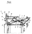
- the pressure device 5 arranged above the horizontal support table 1 has a vertically movable crossbar 17 and two tubes 18 which are rotatably held on the crossbar.
- the tubes 18 extend parallel to the support table and form pressure elements. which rest on an upper edge of the workpiece, not shown here, and can be set in rotation by the workpiece rotating during workpiece machining.
- Slidable shoes 19 are provided on the crossbar 17 for mounting the tubes 18. The distance between the tubes 18 can be adjusted and changed by moving the sliding shoes 19.
- the tubes 18 are designed as telescopic tubes or in the Slide shoes 19 axially displaceable. As a result, the length of the tubes 18 can be adapted accordingly to the workpiece.
- the crossbar can be rotated and locked in a desired angular position.
- support rollers 8, 8 ' can be placed on the outer surface of the workpiece to be machined, the distance from which is adjustable to the pair of beading rollers 3.
- the support rollers 8, 8 ' are mounted on axially adjustable feed elements 15, 15'.
- a pair of support rollers 8 ' can be set to the machining gap of the pair of beads 3.
- the feed elements 15 'of this pair of beads 8' are axially adjustable at right angles to the connecting line between the axes of rotation of the pair of beads 3.
- the pressing device 5 comprises interchangeable weight pieces 20, by the selection of which the pressing force on the workpiece can be adjusted.
- a pneumatically or hydraulically operating lifting device 21 is also provided. The pressure device 5 is connected to the lifting device 21 and is therefore vertically adjustable for the purpose of changing the workpiece.
Landscapes
- Engineering & Computer Science (AREA)
- Mechanical Engineering (AREA)
- Absorbent Articles And Supports Therefor (AREA)
- Jigs For Machine Tools (AREA)
- Polishing Bodies And Polishing Tools (AREA)
- Photoreceptors In Electrophotography (AREA)
- Treatment Of Fiber Materials (AREA)
- Bending Of Plates, Rods, And Pipes (AREA)
Priority Applications (1)
| Application Number | Priority Date | Filing Date | Title |
|---|---|---|---|
| AT91118951T ATE99577T1 (de) | 1990-11-06 | 1991-11-06 | Vorrichtung zum anformen von endseitigen sicken an rohrfoermigen werkstuecken aus blech. |
Applications Claiming Priority (2)
| Application Number | Priority Date | Filing Date | Title |
|---|---|---|---|
| DE9015247U DE9015247U1 (de) | 1990-11-06 | 1990-11-06 | Vorrichtung zum Anformen von endseitigen Sicken an rohrförmigen Werkstücken aus Blech |
| DE9015247U | 1990-11-06 |
Publications (3)
| Publication Number | Publication Date |
|---|---|
| EP0484934A2 true EP0484934A2 (fr) | 1992-05-13 |
| EP0484934A3 EP0484934A3 (en) | 1992-07-29 |
| EP0484934B1 EP0484934B1 (fr) | 1994-01-05 |
Family
ID=6859092
Family Applications (1)
| Application Number | Title | Priority Date | Filing Date |
|---|---|---|---|
| EP91118951A Expired - Lifetime EP0484934B1 (fr) | 1990-11-06 | 1991-11-06 | Dispositif pour former des moulures à la fin des pièces à travailler tubulaires en tôle |
Country Status (3)
| Country | Link |
|---|---|
| EP (1) | EP0484934B1 (fr) |
| AT (1) | ATE99577T1 (fr) |
| DE (2) | DE9015247U1 (fr) |
Cited By (1)
| Publication number | Priority date | Publication date | Assignee | Title |
|---|---|---|---|---|
| KR100448491B1 (ko) * | 2001-09-03 | 2004-09-13 | 기아자동차주식회사 | 파이프 비드 성형장치 |
Families Citing this family (1)
| Publication number | Priority date | Publication date | Assignee | Title |
|---|---|---|---|---|
| CN108776298B (zh) * | 2018-07-27 | 2025-03-11 | 深圳市仕科达精密设备技术有限公司 | Pcb板测试模组及程序烧录测试机 |
Family Cites Families (5)
| Publication number | Priority date | Publication date | Assignee | Title |
|---|---|---|---|---|
| DE571420C (de) * | 1931-07-26 | 1933-02-28 | Saechsische Cartonnagen Maschi | Maschine zum Sicken von Bechern |
| US2251810A (en) * | 1938-08-19 | 1941-08-05 | Quickwork Company | Forming and trimming machine |
| US3595048A (en) * | 1969-01-30 | 1971-07-27 | Teddington Bellows Ltd | Bellows |
| DE2700780A1 (de) * | 1977-01-10 | 1978-07-20 | Heinz Stehle | Verfahren und einrichtung zum anordnen einer dem gegenseitigen verbinden mehrerer blechsegmente dienenden sicke |
| DE8708141U1 (de) * | 1987-06-09 | 1987-07-23 | Siegwart, Emil, 6605 Friedrichsthal | Sickenmaschine |
-
1990
- 1990-11-06 DE DE9015247U patent/DE9015247U1/de not_active Expired - Lifetime
-
1991
- 1991-11-06 EP EP91118951A patent/EP0484934B1/fr not_active Expired - Lifetime
- 1991-11-06 AT AT91118951T patent/ATE99577T1/de not_active IP Right Cessation
- 1991-11-06 DE DE91118951T patent/DE59100811D1/de not_active Expired - Fee Related
Cited By (1)
| Publication number | Priority date | Publication date | Assignee | Title |
|---|---|---|---|---|
| KR100448491B1 (ko) * | 2001-09-03 | 2004-09-13 | 기아자동차주식회사 | 파이프 비드 성형장치 |
Also Published As
| Publication number | Publication date |
|---|---|
| DE9015247U1 (de) | 1991-01-17 |
| DE59100811D1 (de) | 1994-02-17 |
| EP0484934B1 (fr) | 1994-01-05 |
| EP0484934A3 (en) | 1992-07-29 |
| ATE99577T1 (de) | 1994-01-15 |
Similar Documents
| Publication | Publication Date | Title |
|---|---|---|
| DE3534428C2 (fr) | ||
| DE3521047C1 (de) | Mikroskop | |
| EP1827755B1 (fr) | Dispositif servant a polir des surfaces dures, en particulier des surfaces de verre | |
| EP0394531B1 (fr) | Machine à sertir | |
| EP4103352B1 (fr) | Dispositif de support pour une machine d'usinage au laser et machine d'usinage au laser | |
| DE69832426T2 (de) | Pressvorrichtung für Metallblech | |
| CH407522A (de) | Vorrichtung zum Kantenbrechen, insbesondere von plattenförmigen Werkstücken aus Holz, Kunststoff o. dgl. | |
| EP1136206A2 (fr) | Machine avec tête de fraisage pivotable | |
| EP0484934B1 (fr) | Dispositif pour former des moulures à la fin des pièces à travailler tubulaires en tôle | |
| EP0995509A1 (fr) | Plieuse | |
| EP0787560A1 (fr) | Dispositif d'usinage des barres, des profilés et similaire | |
| DE8806277U1 (de) | Maschine zum Ummanteln von Werkstücken | |
| DE9404308U1 (de) | Biegemaschine zum rutschlosen Biegebearbeiten von Blechtafeln | |
| EP0167112B1 (fr) | Procédé et appareil pour fraiser et rainurer des parties d'un cadre en bois | |
| EP0802036A2 (fr) | Appareil pour le soudage bout à bout de tubes en matières thermoplastiques | |
| DE2323737C3 (de) | Vorrichtung zum Gravieren rotationssymmetrischer Werkstücke | |
| EP0060501B1 (fr) | Machine de travail de pièces en arc | |
| DE2709024A1 (de) | Einrichtung zum trennen von rohren und stangen | |
| DE915501C (de) | Steuer- und Einstellvorrichtung, insbesondere fuer Kettenfraesmaschinen mit mehreren Ketten | |
| DE1294272B (de) | Mechanische Nachfuehrvorrichtung | |
| DE102013004201B4 (de) | Tragbare Maschine zur Bearbeitung von Ecken | |
| DE2953348C2 (de) | Schwenkbiegemaschine | |
| DE19615204C1 (de) | Vorrichtung zum Stumpfschweißen von thermoplastischen Kunststoffrohren | |
| DE3640476A1 (de) | Brillengestellkonsole an geraeten zum herstellen von brillenglasformscheiben oder zum bearbeiten von brillenglaesern nach einem brillengestell | |
| DE3344963A1 (de) | Fuehrungseinrichtung fuer handhobel- oder fraesgeraete |
Legal Events
| Date | Code | Title | Description |
|---|---|---|---|
| PUAI | Public reference made under article 153(3) epc to a published international application that has entered the european phase |
Free format text: ORIGINAL CODE: 0009012 |
|
| AK | Designated contracting states |
Kind code of ref document: A2 Designated state(s): AT CH DE FR IT LI |
|
| PUAL | Search report despatched |
Free format text: ORIGINAL CODE: 0009013 |
|
| AK | Designated contracting states |
Kind code of ref document: A3 Designated state(s): AT CH DE FR IT LI |
|
| 17P | Request for examination filed |
Effective date: 19920714 |
|
| 17Q | First examination report despatched |
Effective date: 19930617 |
|
| GRAA | (expected) grant |
Free format text: ORIGINAL CODE: 0009210 |
|
| AK | Designated contracting states |
Kind code of ref document: B1 Designated state(s): AT CH DE FR IT LI |
|
| REF | Corresponds to: |
Ref document number: 99577 Country of ref document: AT Date of ref document: 19940115 Kind code of ref document: T |
|
| ITF | It: translation for a ep patent filed | ||
| REF | Corresponds to: |
Ref document number: 59100811 Country of ref document: DE Date of ref document: 19940217 |
|
| ET | Fr: translation filed | ||
| PLBE | No opposition filed within time limit |
Free format text: ORIGINAL CODE: 0009261 |
|
| STAA | Information on the status of an ep patent application or granted ep patent |
Free format text: STATUS: NO OPPOSITION FILED WITHIN TIME LIMIT |
|
| 26N | No opposition filed | ||
| PGFP | Annual fee paid to national office [announced via postgrant information from national office to epo] |
Ref country code: DE Payment date: 20031117 Year of fee payment: 13 |
|
| PGFP | Annual fee paid to national office [announced via postgrant information from national office to epo] |
Ref country code: CH Payment date: 20031118 Year of fee payment: 13 |
|
| PGFP | Annual fee paid to national office [announced via postgrant information from national office to epo] |
Ref country code: FR Payment date: 20031119 Year of fee payment: 13 |
|
| PGFP | Annual fee paid to national office [announced via postgrant information from national office to epo] |
Ref country code: AT Payment date: 20031125 Year of fee payment: 13 |
|
| PG25 | Lapsed in a contracting state [announced via postgrant information from national office to epo] |
Ref country code: AT Free format text: LAPSE BECAUSE OF NON-PAYMENT OF DUE FEES Effective date: 20041106 |
|
| PG25 | Lapsed in a contracting state [announced via postgrant information from national office to epo] |
Ref country code: CH Free format text: LAPSE BECAUSE OF NON-PAYMENT OF DUE FEES Effective date: 20041130 Ref country code: LI Free format text: LAPSE BECAUSE OF NON-PAYMENT OF DUE FEES Effective date: 20041130 |
|
| PG25 | Lapsed in a contracting state [announced via postgrant information from national office to epo] |
Ref country code: DE Free format text: LAPSE BECAUSE OF NON-PAYMENT OF DUE FEES Effective date: 20050601 |
|
| REG | Reference to a national code |
Ref country code: CH Ref legal event code: PL |
|
| PG25 | Lapsed in a contracting state [announced via postgrant information from national office to epo] |
Ref country code: FR Free format text: LAPSE BECAUSE OF NON-PAYMENT OF DUE FEES Effective date: 20050729 |
|
| REG | Reference to a national code |
Ref country code: FR Ref legal event code: ST |
|
| PGFP | Annual fee paid to national office [announced via postgrant information from national office to epo] |
Ref country code: IT Payment date: 20101122 Year of fee payment: 20 |