EP0484935A2 - Méthode et dispositif pour lire et identifier l'information réprésentée par des signes, en particulier un code à barres, dans un champs deux-/ou trois-dimensionnel à l'aide d'une caméra vidéo qui est capable de générer un signal vidéo numérique de l'image - Google Patents
Méthode et dispositif pour lire et identifier l'information réprésentée par des signes, en particulier un code à barres, dans un champs deux-/ou trois-dimensionnel à l'aide d'une caméra vidéo qui est capable de générer un signal vidéo numérique de l'image Download PDFInfo
- Publication number
- EP0484935A2 EP0484935A2 EP91118979A EP91118979A EP0484935A2 EP 0484935 A2 EP0484935 A2 EP 0484935A2 EP 91118979 A EP91118979 A EP 91118979A EP 91118979 A EP91118979 A EP 91118979A EP 0484935 A2 EP0484935 A2 EP 0484935A2
- Authority
- EP
- European Patent Office
- Prior art keywords
- binary
- derivative
- video signal
- image
- signal
- Prior art date
- Legal status (The legal status is an assumption and is not a legal conclusion. Google has not performed a legal analysis and makes no representation as to the accuracy of the status listed.)
- Granted
Links
Images

Classifications
-
- G—PHYSICS
- G06—COMPUTING OR CALCULATING; COUNTING
- G06K—GRAPHICAL DATA READING; PRESENTATION OF DATA; RECORD CARRIERS; HANDLING RECORD CARRIERS
- G06K7/00—Methods or arrangements for sensing record carriers, e.g. for reading patterns
- G06K7/10—Methods or arrangements for sensing record carriers, e.g. for reading patterns by electromagnetic radiation, e.g. optical sensing; by corpuscular radiation
- G06K7/10544—Methods or arrangements for sensing record carriers, e.g. for reading patterns by electromagnetic radiation, e.g. optical sensing; by corpuscular radiation by scanning of the records by radiation in the optical part of the electromagnetic spectrum
- G06K7/10821—Methods or arrangements for sensing record carriers, e.g. for reading patterns by electromagnetic radiation, e.g. optical sensing; by corpuscular radiation by scanning of the records by radiation in the optical part of the electromagnetic spectrum further details of bar or optical code scanning devices
- G06K7/1092—Methods or arrangements for sensing record carriers, e.g. for reading patterns by electromagnetic radiation, e.g. optical sensing; by corpuscular radiation by scanning of the records by radiation in the optical part of the electromagnetic spectrum further details of bar or optical code scanning devices sensing by means of TV-scanning
Definitions
- the invention relates to a method for reading and identifying the information of an image, in particular barcode, within a two- or three-dimensional field by means of a video camera, which generates a binary video signal of the image according to the preamble of claim 1; the invention also relates to a device for carrying out the method.
- Such image information recognition systems can have a reciprocating laser beam and logic circuits or software programs, by means of which the bar codes printed on the articles are optically read and the electrical signals generated by the laser are interpreted.
- a prerequisite for the known image information recognition systems is that the character of the information must be known to the reader, which means that the reader must be specifically designed for the information to be read and interpreted, whether it is, for example, alphanumeric characters or is a barcode.
- the reader For image information processing it is imperative that between the arrangement of the images or characters containing the information and the sensor receiving the information, a fixed or variable geometric assignment is ensured; For example, a laser reader must be guided across the barcode perpendicularly or almost perpendicularly to the barcode in order to ensure correct recognition of the image or the information.
- Image information recording is a mandatory requirement that the images, whether barcode or alphanumeric characters, must have a minimum contrast to their surroundings.
- the known image information recognition systems can therefore not be used to read and interpret images or characters that have contrast disturbances and / or damage to a greater or lesser extent.
- problems frequently arise, for example due to oil stains, mechanical stresses, the application of mechanical, transparent protective layers, but also due to thermal or chemical treatments in technological processes, and all of them are unavoidable in an industrial environment.
- Another problem is that three-dimensionally arranged information, for example alpha-numeric characters or bar codes etched into the surface of a metallic object, cannot be read with the known image information recognition systems.
- the invention has for its object to provide a method and an apparatus in which the information to be read and interpreted by means of a video camera in the form of a character template as such is recognized qualitatively independently of the geometric assignment of the character template to the reader and the character template itself major damage, soiling or contrast disturbances in order to be read and interpreted correctly.
- the invention is based on the object of using a video camera to correctly read and interpret a barcode which is arbitrarily arranged within a surface or in space and has faults.
- the first derivative (f '(t)) is advantageously differentiated again and also fed to a window comparator, the switching edges of the second derivative (f' '(t)) are evaluated by means of a Schmitt trigger whose output signal (c2 (t)) again differentiated and linked with the output signal (c1 (t)) of the window comparator, a flip-flop taking over the signals of the switching edges of the second derivative and performing the linking.
- the flip-flop is advantageously a JK flip-flop, the data of the Schmitt trigger with the generating edges being taken over and the sampling frequency of the binary image being greater than or equal to the sampling frequency of the video camera.
- the autocorrelation function within a local environment is calculated for a plurality of locations, a local maximum (MAX) and / or the associated direction angle (DIR) being ascertained by means of segmentation from the obtained values of the autocorrelation.
- a local maximum (MAX) and / or the associated direction angle (DIR) being ascertained by means of segmentation from the obtained values of the autocorrelation.
- an accumulation method is advantageously used in that an enclosing contour, preferably a rectangle, is specified and a directional accumulation takes place within the contour.
- the autocorrelation can be calculated for eight displacement vectors, these being selected so that they correspond to the displacement from the central point, for example a 5 ⁇ 5 environment, towards edge points.
- a cross-correlation of the measured values can be calculated with a sine curve and the phase position and thus the angle of rotation of the parallel structures can be determined from the maximum obtained in this way.
- Fields with the same or adjacent direction with a minimum amplitude are advantageously combined into objects and the center of gravity is determined for objects of a certain size; the circumscribing rectangle of the object is defined by the center of gravity parallel to the main axis as well as orthogonal to the digital lines; The number of black and white pixels is counted orthogonally to the main lines to determine the accumulated intensity distribution along the main axis of the barcode.
- the video signal (f (t)) can advantageously pass through a low-pass filter before the first derivative (f '(t)) is formed.
- the method and the device according to the invention have the advantage that contrast disturbances and damage or incompleteness of the object can be accepted to a much greater extent with the image information recognition system and the object can still be reliably recognized as such and can be interpreted.
- they may be damaged, contrast disturbances or soiling, such as cracks, oil stains, poor contrast, to a large extent, so that they can still be read and interpreted perfectly, which is not possible with the conventional methods.
- the method according to the invention when applied to barcodes, ensures that the readability is shifted as desired or rotated within wide limits in the predetermined field of view of the video camera.
- the distance between the camera and the object or barcode can be adjusted within wide limits by selecting suitable lenses; the depth of field corresponds to that of the usual photo lenses.
- moving objects can be read and interpreted in an advantageous manner, e.g. especially moving barcodes.
- a CCD shutter video camera By using a CCD shutter video camera, a sufficiently short exposure time can be achieved to adapt the method according to the invention, the relative speed of the bar code advantageously being smaller than the quotient of the minimum structure width of the bar code (mode) divided by the exposure time of the CCD Video camera should be.
- FIG. 1 A video camera 1 (TV) with an optical lens records a drawing template 2, which is, for example, a barcode, after which the resulting video signal f (t) is fed to a binary image processor 3 (BIP), the output signal BIN of which is on the one hand a correlator 4 (KOR) and on the other hand, can be fed directly to an image memory 5 (MEM).
- BIP binary image processor 3
- KOR correlator 4
- MEM image memory 5
- the outputs DIR and MAX of the correlator 4 are also connected to the image memory 5, which is connected via a bus 6 to a central processing unit 7 (CPU).
- the video camera 1 can have a line or area sensor with basically known synchronization devices (genlock), such as clock generators, among others, and can be supplemented by an electronic quick lock (shutter).
- a CCD line scan camera or a one-dimensionally deflected laser scanner can be used; the deflection in the second direction occurs either through the natural movement of the drawing template (object) or through an optical deflection system.
- a CCD matrix camera is used.
- a CCD camera is expediently used, the shutter or integration time control of which is adapted to the movement.
- FIG. 2 shows the signal processing and the structural design of the binary image processor 3.
- the video signal is first freed of high-frequency noise and possible clock disturbances by means of a low-pass filter 8.
- two differentiators 9 and 10 with an output for the first derivative f '(t) and an output for the second derivative f' '(t) of the video signal f (t) are arranged in time and the video signal is differentiated accordingly .
- the output signal c1 (t) of the window comparator 13 is passed through a delay element 14 with the delay time ⁇ 1 to the runtime compensation and then fed to a logic element 12; the use of the window comparator 13 and of the delay element 14 represent an advantageous addition to the logic module 12.
- the output signal c1 (t) of the delay element is linked within an AND gate 16 with the signal c3 (T n ) and the sum signal EN is formed:
- the EN signal only allows the switching edges to pass that meet the features a) to c), the switching edges being those points at which c2 (t) changes and thus a third derivative c3 (t) is present.
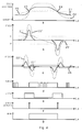
- FIG. 4a shows a black and white jump in the video signal f (t), the solid curve 21 being one with low illuminance, the dotted curve 22 being one with high illuminance and the dotted curve 25 being such in the defocused state;
- FIGS. 4b and 4c show the 1st and 2nd derivatives over time; the dotted curve 25 'in FIG. 4b means the same function in the defocused state.
- a window A-A '(FIG. 4b) is therefore formed by a threshold value decision from the first derivative, in which the contrast is evaluated and in which the zeros of the second derivative can be evaluated.
- This window is lighting-dependent, but less critical than the known direct threshold value decision in the video signal.
- the second derivative is also zero in the area of constant blackening, so that noise and other disturbances could lead to edges of the Schmitt trigger 11 here. This means that only the zeros of the 2nd derivative are evaluated, which lie above a contrast threshold that results from the 1st derivative.
- the hysteresis 26 (in FIG. 2 "H") of the Schmitt trigger 11 acts in a similar manner to suppress interference.
- the signal c2 (t) from the Schmitt trigger 11 is shown in FIG. 4d.
- the high sensitivity of the method also provides contours in the binary image with low contrast details, which are permitted or forbidden as required by selecting thresholds H and S and possibly A-A ', i.e. can be specified.
- the scanning of the binary image is carried out at a sampling frequency which can advantageously be above the pixel frequency of the video camera. This is advantageous if a higher scanning accuracy is to be achieved with sub-pixel interpolation in known image structures, for example bar codes.
- the length is determined here more precisely than the grid of the scanner actually allows.
- the gray value resolution is reduced in order to increase the length resolution, what is advantageously given up to a resolution of approximately 4: 1.
- Figures 4 e-g show the associated function of c1 (t) of the window comparator 13, as well as the signal EN (t) and the associated binary signal BIN.
- Figures 5 to 7 show the signal processing of the correlator 4 (KOR).
- the general task of the correlator 4 is to analyze the mapping structure of the object and to determine predetermined or sought structures. If it is a bar code, the task of the correlator 4 is in particular to detect parallel line structures of the bar code and to determine their direction.
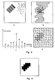
- the autocorrelation function ACF is determined in a local environment ( ⁇ x. ⁇ y) of a test point (P ⁇ x0, y0 ⁇ ) within the field of view of the video camera in order to specify a dependency measure in this way.
- the ACF has characteristic maxima (displacement vector R ⁇ in the direction of the bars) and minima (displacement vector R ⁇ perpendicular to these).
- the minimum of the ACF is exactly in the direction rotated by 90 degrees to DIR (max).
- the normalized difference (KTR) a measure of contrast for existing bar code and can be used directly for the segmentation shown in FIG. 6.
- FIG. 5 shows a possibility of selecting the support points for determining the ACF (with the same angular rotation ⁇ ), in FIG. 5 d the result of the correlation is shown.
- the local environment has the format 5x5 picture elements, of which, for reasons of symmetry, however, only the picture points above the central point need to be taken into account, for example.
- the current and two previous lines are held in shift registers, possibly with RAM support.
- the desired picture elements can be reached via taps and linked according to FIG. 5 b, wherein the outputs of the EXOR links are clocked by counters.
- the meters contain intermediate values of the ACF, which then have to be added in the vertical direction.
- the maximum MAX of the ACF is determined via a table (memory) or several hierarchically arranged comparators and multiplexers and the assigned direction (DIR) is output.
- DIR the measured values of the ACF (DIR), ie the frequencies of the occurrence of the directions, are specified.
- the values MAX, MIN and DIR are saved as a function of the coordinates of the assigned measuring fields ( ⁇ x. ⁇ y).
- the position of the bar code in the image and its angle of rotation are detected from these measurement matrices by means of threshold value decisions.
- the area in which the barcode is located is segmented, which is shown in FIG. 6. For this purpose, related objects with identical or adjacent directions are determined.
- the segmentation is used to detect parallel structures, such as barcodes, in binary images.
- the autocorrelation is calculated for 8 displacement vectors.
- the displacement vectors are chosen so that they correspond to the displacement from the central point of a 5 x 5 environment to edge points. For reasons of symmetry, only 8 of the 16 boundary points have to be taken into account:
- the overall image of, for example, 384 x 288 pixels is advantageously divided into 24 x 18 fields of 16 x 16 pixels.
- the autocorrelation is calculated for fields of 16 x 16 pixels so that the 5 x 5 surroundings are completely within the field.
- a cross correlation of the measured values with a sine curve is calculated for the exact detection of the angle of rotation.
- the maximum of the correlation becomes the phase position and thus the angle of rotation of the parallel structures are determined.
- the amplitude (difference between maximum and minimum of the correlation values) is a measure of the presence of parallel structures within the field.
- the result is a structure of size 24 x 18 with the absolute direction value and the amplitude.
- fields with the same or adjacent direction, in which the amplitude exceeds a certain threshold are combined to form objects.
- the center of gravity is determined for objects of a certain size.
- a circumscribing rectangle of the object is defined parallel to the main axis (orthogonal to the direction of the digital route through the center of gravity):
- the number of black and white pixels is counted orthogonally to the main lines. The result is the accumulated intensity distribution along the main axis of the barcode.
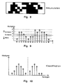
- the precise measurement of the angle of rotation of the bar code takes place within the objects by correlating image lines within the bar code field and the directional accumulation of the bar code (FIG. 8). For this purpose, a number of digital measuring lines with the calculated angle of rotation are laid within the object. The white and black pixels that lie within the object to be examined are counted separately on each of these measuring lines (FIG. 9); the measuring line is then assigned the value "white” if more white than black points have been found, otherwise black, as shown in FIG. 9.
- the ordered sequence of the measured values obtained in this way is coded run-length (FIG. 10), and run-length histograms are determined, separated for white and black, i.e. from the distribution of intensity.
- the thresholds for the lengths of the runs are determined from these histograms. This divides the white and black stripes according to their width. On the basis of this classification data, the type of the present bar code is recognized and its decoding.
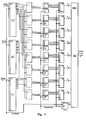
- FIG. 7 shows a possible structure of the correlator 4.
- the local environment has (2N + 1) columns and two rows; the current and the previous line are in shift registers 27, 27 ', 27''.
- the picture elements according to FIG. 5 can be linked via taps.
- the EXOR links clock downstream counter 280, 281, 282, 283, 284, 285, 286, 287, in which after the integration the ACF (x0, y0, ⁇ K , ⁇ K ) is.
- the maximum MAX of the ACF is formed via a table 29 (MUX) or staggered comparators and multiplexers and the direction DIR is switched to the output.
- the table (MUX) excludes special states, for example completely white or completely black zones, and ensures an interpolation of the direction between the nodes; the table can also be created by a hierarchical comparator arrangement.
- the object of the invention can advantageously be used industrially in image information recognition systems with which an object can still be reliably recognized and interpreted as such despite contrast disturbances, damage, soiling or incompleteness, in particular for reading and interpreting bar codes.
- the object of the invention can be used in particular in automatic reading stations and, when used for recognizing bar codes, ensures the readability of the same, displaced as desired or rotated within wide limits in the predetermined field of view of the video camera.
Landscapes
- Physics & Mathematics (AREA)
- Electromagnetism (AREA)
- Engineering & Computer Science (AREA)
- Health & Medical Sciences (AREA)
- General Health & Medical Sciences (AREA)
- Toxicology (AREA)
- Artificial Intelligence (AREA)
- Computer Vision & Pattern Recognition (AREA)
- General Physics & Mathematics (AREA)
- Theoretical Computer Science (AREA)
- Image Analysis (AREA)
Applications Claiming Priority (2)
| Application Number | Priority Date | Filing Date | Title |
|---|---|---|---|
| DE4035396 | 1990-11-07 | ||
| DE4035396A DE4035396A1 (de) | 1990-11-07 | 1990-11-07 | Verfahren und vorrichtung zum lesen und identifizieren der information einer zeichen-vorlage, insbesondere barcode, innerhalb eines zwei- oder dreidimensionalen feldes mittels einer videokamera, die ein binaeres videosignal des bildes erzeugt |
Publications (3)
| Publication Number | Publication Date |
|---|---|
| EP0484935A2 true EP0484935A2 (fr) | 1992-05-13 |
| EP0484935A3 EP0484935A3 (en) | 1993-04-14 |
| EP0484935B1 EP0484935B1 (fr) | 1997-01-15 |
Family
ID=6417810
Family Applications (1)
| Application Number | Title | Priority Date | Filing Date |
|---|---|---|---|
| EP91118979A Expired - Lifetime EP0484935B1 (fr) | 1990-11-07 | 1991-11-07 | Méthode et dispositif pour lire et identifier l'information réprésentée par des signes, en particulier un code à barres, dans un champs deux-/ou trois-dimensionnel à l'aide d'une caméra vidéo qui est capable de générer un signal vidéo numérique de l'image |
Country Status (3)
| Country | Link |
|---|---|
| EP (1) | EP0484935B1 (fr) |
| DE (2) | DE4035396A1 (fr) |
| ES (1) | ES2103291T3 (fr) |
Cited By (15)
| Publication number | Priority date | Publication date | Assignee | Title |
|---|---|---|---|---|
| EP0569962A3 (fr) * | 1992-05-14 | 1994-03-02 | United Parcel Service Inc | |
| EP0592736A1 (fr) * | 1991-03-25 | 1994-04-20 | Opticon Inc. | Méthode et appareil pour lire et décoder une code à barres |
| EP0591635A3 (en) * | 1992-08-10 | 1994-06-22 | United Parcel Service Inc | Method and apparatus for decoding bar code symbols using subpixel interpolation |
| WO1995034043A1 (fr) * | 1994-06-07 | 1995-12-14 | United Parcel Service Of America, Inc. | Procede et appareil permettant de decoder des symboles bidimensi onnels dans le domaine spatial |
| WO1997014110A1 (fr) * | 1995-10-13 | 1997-04-17 | Meta Holding Corporation | Lecteurs de formes de donnees inferieures au pixel |
| CN1035287C (zh) * | 1992-02-20 | 1997-06-25 | 欧林巴斯光学工业股份有限公司 | 条形码记号读取装置 |
| CN1036807C (zh) * | 1992-05-26 | 1997-12-24 | 欧林巴斯光学工业股份有限公司 | 带自动阅读开始功能的条形码阅读装置 |
| CN1037380C (zh) * | 1992-05-26 | 1998-02-11 | 欧林巴斯光学工业股份有限公司 | 符号信息读取装置 |
| CN1038789C (zh) * | 1992-09-10 | 1998-06-17 | 欧林巴斯光学工业股份有限公司 | 条形码记号读取装置 |
| CN1041246C (zh) * | 1993-03-12 | 1998-12-16 | 欧林巴斯光学工业股份有限公司 | 采用ccd技术阅读二维条码的装置和方法 |
| CN1043545C (zh) * | 1992-05-29 | 1999-06-02 | 欧林巴斯光学工业股份有限公司 | 条形码读取装置 |
| CN1043933C (zh) * | 1992-08-31 | 1999-06-30 | 欧林巴斯光学工业股份有限公司 | 记号信息的读取装置 |
| US6250551B1 (en) * | 1998-06-12 | 2001-06-26 | Symbol Technologies, Inc. | Autodiscrimination and line drawing techniques for code readers |
| WO2004006438A3 (fr) * | 2002-07-08 | 2004-04-29 | Veritec Inc | Procede de lecture d'un symbole contenant des informations codees |
| US9990520B2 (en) | 2008-10-31 | 2018-06-05 | Hand Held Products, Inc. | Indicia reading terminal including frame quality evaluation processing |
Families Citing this family (1)
| Publication number | Priority date | Publication date | Assignee | Title |
|---|---|---|---|---|
| DE19945837C2 (de) * | 1999-09-24 | 2003-11-27 | Leuze Electronic Gmbh & Co Kg | Optoelektronische Vorrichtung zum Erkennen von Barcodes |
Family Cites Families (5)
| Publication number | Priority date | Publication date | Assignee | Title |
|---|---|---|---|---|
| US3892949A (en) * | 1974-04-22 | 1975-07-01 | Rca Corp | Circuit for determining the time of transitions in an alternating signal |
| US4000397A (en) * | 1975-03-21 | 1976-12-28 | Spectra-Physics, Inc. | Signal processor method and apparatus |
| DE3279040D1 (en) * | 1981-04-09 | 1988-10-20 | Recognition Equipment Inc | Ocr and bar code reader with optimized sensor |
| DE3203897A1 (de) * | 1981-11-07 | 1983-05-19 | Licentia Patent-Verwaltungs-Gmbh, 6000 Frankfurt | Vorrichtung zur erkennung und verarbeitung von zeichen und/oder vorgegebenen optischen details |
| US4387298A (en) * | 1981-11-27 | 1983-06-07 | Burroughs Corporation | Recognition logic circuit for bar code reader systems |
-
1990
- 1990-11-07 DE DE4035396A patent/DE4035396A1/de active Granted
-
1991
- 1991-11-07 DE DE59108488T patent/DE59108488D1/de not_active Expired - Fee Related
- 1991-11-07 EP EP91118979A patent/EP0484935B1/fr not_active Expired - Lifetime
- 1991-11-07 ES ES91118979T patent/ES2103291T3/es not_active Expired - Lifetime
Cited By (20)
| Publication number | Priority date | Publication date | Assignee | Title |
|---|---|---|---|---|
| EP0592736A1 (fr) * | 1991-03-25 | 1994-04-20 | Opticon Inc. | Méthode et appareil pour lire et décoder une code à barres |
| CN1035287C (zh) * | 1992-02-20 | 1997-06-25 | 欧林巴斯光学工业股份有限公司 | 条形码记号读取装置 |
| EP0569962A3 (fr) * | 1992-05-14 | 1994-03-02 | United Parcel Service Inc | |
| CN1037380C (zh) * | 1992-05-26 | 1998-02-11 | 欧林巴斯光学工业股份有限公司 | 符号信息读取装置 |
| CN1036807C (zh) * | 1992-05-26 | 1997-12-24 | 欧林巴斯光学工业股份有限公司 | 带自动阅读开始功能的条形码阅读装置 |
| CN1043545C (zh) * | 1992-05-29 | 1999-06-02 | 欧林巴斯光学工业股份有限公司 | 条形码读取装置 |
| EP0591635A3 (en) * | 1992-08-10 | 1994-06-22 | United Parcel Service Inc | Method and apparatus for decoding bar code symbols using subpixel interpolation |
| CN1043933C (zh) * | 1992-08-31 | 1999-06-30 | 欧林巴斯光学工业股份有限公司 | 记号信息的读取装置 |
| CN1038789C (zh) * | 1992-09-10 | 1998-06-17 | 欧林巴斯光学工业股份有限公司 | 条形码记号读取装置 |
| CN1041246C (zh) * | 1993-03-12 | 1998-12-16 | 欧林巴斯光学工业股份有限公司 | 采用ccd技术阅读二维条码的装置和方法 |
| US6094509A (en) * | 1994-06-07 | 2000-07-25 | United Parcel Service Of America, Inc. | Method and apparatus for decoding two-dimensional symbols in the spatial domain |
| WO1995034043A1 (fr) * | 1994-06-07 | 1995-12-14 | United Parcel Service Of America, Inc. | Procede et appareil permettant de decoder des symboles bidimensi onnels dans le domaine spatial |
| US5979763A (en) * | 1995-10-13 | 1999-11-09 | Metanetics Corporation | Sub-pixel dataform reader with dynamic noise margins |
| WO1997014110A1 (fr) * | 1995-10-13 | 1997-04-17 | Meta Holding Corporation | Lecteurs de formes de donnees inferieures au pixel |
| US6250551B1 (en) * | 1998-06-12 | 2001-06-26 | Symbol Technologies, Inc. | Autodiscrimination and line drawing techniques for code readers |
| US6405925B2 (en) | 1998-06-12 | 2002-06-18 | Symbol Technologies, Inc. | Autodiscrimination and line drawing techniques for code readers |
| WO2004006438A3 (fr) * | 2002-07-08 | 2004-04-29 | Veritec Inc | Procede de lecture d'un symbole contenant des informations codees |
| US7159780B2 (en) | 2002-07-08 | 2007-01-09 | Veritec, Inc. | Method for reading a symbol having encoded information |
| US9990520B2 (en) | 2008-10-31 | 2018-06-05 | Hand Held Products, Inc. | Indicia reading terminal including frame quality evaluation processing |
| US10296770B2 (en) | 2008-10-31 | 2019-05-21 | Hand Held Products, Inc. | Indicia reading terminal including frame quality evaluation processing |
Also Published As
| Publication number | Publication date |
|---|---|
| DE4035396A1 (de) | 1992-05-14 |
| ES2103291T3 (es) | 1997-09-16 |
| EP0484935B1 (fr) | 1997-01-15 |
| DE4035396C2 (fr) | 1993-08-05 |
| DE59108488D1 (de) | 1997-02-27 |
| EP0484935A3 (en) | 1993-04-14 |
Similar Documents
| Publication | Publication Date | Title |
|---|---|---|
| EP0484935B1 (fr) | Méthode et dispositif pour lire et identifier l'information réprésentée par des signes, en particulier un code à barres, dans un champs deux-/ou trois-dimensionnel à l'aide d'une caméra vidéo qui est capable de générer un signal vidéo numérique de l'image | |
| Von Gioi et al. | LSD: A fast line segment detector with a false detection control | |
| DE69533054T2 (de) | Mehrfenstertechnik zur Schwellenwertverarbeitung eines Bildes unter Verwendung lokaler Bildeigenschaften | |
| EP0338677B1 (fr) | Procédé de traitement des images pour reconnaissance de formes | |
| EP0993651B1 (fr) | Marque de repere, procede de reconnaissance de marques de repere et procede de mesure d'objets | |
| EP2417561B1 (fr) | Code a deux dimensions et procede | |
| DE60303202T2 (de) | System und verfahren zum identifizieren und extrahieren von zeichenketten aus erfassten bilddaten | |
| DE69415048T2 (de) | Verfahren und apparat zum bestimmen der genauen winkelorientierung von strichc0desymbolen in zweidimentionalen ccd-bildern | |
| DE69624614T2 (de) | Verfahren zur Stereoübereinstimmungs- und Ungleichheitsmessung | |
| DE102015005267B4 (de) | Informationsverarbeitungsvorrichtung, Verfahren dafür und Messvorrichtung | |
| DE60124604T2 (de) | Stereobildmessvorrichtung | |
| DE2417282B2 (de) | Vorrichtung zum Lesen von Fingerabdrücken | |
| DE2702452C2 (de) | Einrichtung zur Lagebestimmung eines einen anderen Remissionsgrad als der Hintergrund aufweisenden Objektes | |
| DE69423607T2 (de) | Verfahren zum klassifizieren von bildern mit ausgabeabbildungen | |
| EP0414113B1 (fr) | Procédé pour la compensation de mouvement dans un codeur ou un décodeur des images mouvantes | |
| DE60019119T2 (de) | System und Verfahren zur Objekterkennung | |
| WO2022018019A1 (fr) | Procédé et système ou dispositif pour reconnaître un objet dans une image électronique | |
| DE19882767B3 (de) | Randerfassungsverfahren und -vorrichtung für durch Schrotrauschen begrenzte Signale | |
| DE69424086T2 (de) | Bildprozessor | |
| DE102019115224A1 (de) | System und verfahren zum auffinden und klassifizieren von linien in einem bild mittels eines schichtsystems | |
| DE102004026782A1 (de) | Verfahren und Vorrichtung zur rechnergestützten Bewegungsschätzung in mindestens zwei zeitlich aufeinander folgenden digitalen Bildern, computerlesbares Speichermedium und Computerprogramm-Element | |
| DE10143522C2 (de) | Verfahren und Vorrichtung zum Untersuchen eines Objekts | |
| DE10142457B4 (de) | Digitale Bildmessung retroreflektierender Marken | |
| Elmabrouk et al. | Edge detection using local histogram analysis | |
| DE19507059B9 (de) | Verfahren zur omnidirektionalen Erfassung von OCR-Klarschrift auf Etiketten oder ähnlichen Datenträgern durch zufallsgesteuerte Suche und Dekodierung mit einem neuronalen Netzwerk |
Legal Events
| Date | Code | Title | Description |
|---|---|---|---|
| PUAI | Public reference made under article 153(3) epc to a published international application that has entered the european phase |
Free format text: ORIGINAL CODE: 0009012 |
|
| AK | Designated contracting states |
Kind code of ref document: A2 Designated state(s): CH DE ES FR GB IT LI SE |
|
| PUAL | Search report despatched |
Free format text: ORIGINAL CODE: 0009013 |
|
| AK | Designated contracting states |
Kind code of ref document: A3 Designated state(s): CH DE ES FR GB IT LI SE |
|
| 17P | Request for examination filed |
Effective date: 19930609 |
|
| 17Q | First examination report despatched |
Effective date: 19950718 |
|
| GRAG | Despatch of communication of intention to grant |
Free format text: ORIGINAL CODE: EPIDOS AGRA |
|
| GRAH | Despatch of communication of intention to grant a patent |
Free format text: ORIGINAL CODE: EPIDOS IGRA |
|
| GRAH | Despatch of communication of intention to grant a patent |
Free format text: ORIGINAL CODE: EPIDOS IGRA |
|
| GRAA | (expected) grant |
Free format text: ORIGINAL CODE: 0009210 |
|
| AK | Designated contracting states |
Kind code of ref document: B1 Designated state(s): CH DE ES FR GB IT LI SE |
|
| REG | Reference to a national code |
Ref country code: CH Ref legal event code: EP |
|
| REF | Corresponds to: |
Ref document number: 59108488 Country of ref document: DE Date of ref document: 19970227 |
|
| REG | Reference to a national code |
Ref country code: CH Ref legal event code: NV Representative=s name: PATENTANWALTSBUERO G. PETSCHNER |
|
| ITF | It: translation for a ep patent filed | ||
| ET | Fr: translation filed | ||
| GBT | Gb: translation of ep patent filed (gb section 77(6)(a)/1977) |
Effective date: 19970516 |
|
| REG | Reference to a national code |
Ref country code: ES Ref legal event code: FG2A Ref document number: 2103291 Country of ref document: ES Kind code of ref document: T3 |
|
| PLBE | No opposition filed within time limit |
Free format text: ORIGINAL CODE: 0009261 |
|
| STAA | Information on the status of an ep patent application or granted ep patent |
Free format text: STATUS: NO OPPOSITION FILED WITHIN TIME LIMIT |
|
| 26N | No opposition filed | ||
| REG | Reference to a national code |
Ref country code: GB Ref legal event code: 732E |
|
| REG | Reference to a national code |
Ref country code: FR Ref legal event code: TP |
|
| REG | Reference to a national code |
Ref country code: CH Ref legal event code: PUE Owner name: F & O ELECTRONIC SYSTEMS GMBH TRANSFER- BAUMER OPT |
|
| PGFP | Annual fee paid to national office [announced via postgrant information from national office to epo] |
Ref country code: ES Payment date: 19981130 Year of fee payment: 8 |
|
| PG25 | Lapsed in a contracting state [announced via postgrant information from national office to epo] |
Ref country code: ES Free format text: LAPSE BECAUSE OF NON-PAYMENT OF DUE FEES Effective date: 19991108 |
|
| REG | Reference to a national code |
Ref country code: CH Ref legal event code: NV Representative=s name: FREI PATENTANWALTSBUERO |
|
| REG | Reference to a national code |
Ref country code: GB Ref legal event code: IF02 |
|
| PGFP | Annual fee paid to national office [announced via postgrant information from national office to epo] |
Ref country code: SE Payment date: 20031126 Year of fee payment: 13 Ref country code: GB Payment date: 20031126 Year of fee payment: 13 Ref country code: CH Payment date: 20031126 Year of fee payment: 13 |
|
| REG | Reference to a national code |
Ref country code: ES Ref legal event code: FD2A Effective date: 20001214 |
|
| PG25 | Lapsed in a contracting state [announced via postgrant information from national office to epo] |
Ref country code: GB Free format text: LAPSE BECAUSE OF NON-PAYMENT OF DUE FEES Effective date: 20041107 |
|
| PG25 | Lapsed in a contracting state [announced via postgrant information from national office to epo] |
Ref country code: SE Free format text: LAPSE BECAUSE OF NON-PAYMENT OF DUE FEES Effective date: 20041108 |
|
| PG25 | Lapsed in a contracting state [announced via postgrant information from national office to epo] |
Ref country code: CH Free format text: LAPSE BECAUSE OF NON-PAYMENT OF DUE FEES Effective date: 20041130 Ref country code: LI Free format text: LAPSE BECAUSE OF NON-PAYMENT OF DUE FEES Effective date: 20041130 |
|
| GBPC | Gb: european patent ceased through non-payment of renewal fee |
Effective date: 20041107 |
|
| EUG | Se: european patent has lapsed | ||
| REG | Reference to a national code |
Ref country code: CH Ref legal event code: PL |
|
| PGFP | Annual fee paid to national office [announced via postgrant information from national office to epo] |
Ref country code: IT Payment date: 20071129 Year of fee payment: 17 |
|
| PGFP | Annual fee paid to national office [announced via postgrant information from national office to epo] |
Ref country code: FR Payment date: 20071121 Year of fee payment: 17 |
|
| PGFP | Annual fee paid to national office [announced via postgrant information from national office to epo] |
Ref country code: DE Payment date: 20080103 Year of fee payment: 17 |
|
| PG25 | Lapsed in a contracting state [announced via postgrant information from national office to epo] |
Ref country code: IT Free format text: LAPSE BECAUSE OF NON-PAYMENT OF DUE FEES Effective date: 20081107 |
|
| REG | Reference to a national code |
Ref country code: FR Ref legal event code: ST Effective date: 20090731 |
|
| PG25 | Lapsed in a contracting state [announced via postgrant information from national office to epo] |
Ref country code: DE Free format text: LAPSE BECAUSE OF NON-PAYMENT OF DUE FEES Effective date: 20090603 |
|
| PG25 | Lapsed in a contracting state [announced via postgrant information from national office to epo] |
Ref country code: FR Free format text: LAPSE BECAUSE OF NON-PAYMENT OF DUE FEES Effective date: 20081130 |