EP0993651B1 - Marque de repere, procede de reconnaissance de marques de repere et procede de mesure d'objets - Google Patents
Marque de repere, procede de reconnaissance de marques de repere et procede de mesure d'objets Download PDFInfo
- Publication number
- EP0993651B1 EP0993651B1 EP98939536A EP98939536A EP0993651B1 EP 0993651 B1 EP0993651 B1 EP 0993651B1 EP 98939536 A EP98939536 A EP 98939536A EP 98939536 A EP98939536 A EP 98939536A EP 0993651 B1 EP0993651 B1 EP 0993651B1
- Authority
- EP
- European Patent Office
- Prior art keywords
- features
- measuring
- continuity
- measuring mark
- grey
- Prior art date
- Legal status (The legal status is an assumption and is not a legal conclusion. Google has not performed a legal analysis and makes no representation as to the accuracy of the status listed.)
- Expired - Lifetime
Links
Images
Classifications
-
- G—PHYSICS
- G06—COMPUTING OR CALCULATING; COUNTING
- G06V—IMAGE OR VIDEO RECOGNITION OR UNDERSTANDING
- G06V10/00—Arrangements for image or video recognition or understanding
- G06V10/20—Image preprocessing
- G06V10/24—Aligning, centring, orientation detection or correction of the image
- G06V10/245—Aligning, centring, orientation detection or correction of the image by locating a pattern; Special marks for positioning
Definitions
- the invention relates to a method for the detection of measuring marks according to the preamble of claim 1 and a method for object measurement according to the preamble of claim 12 and a measuring mark according to the preamble of the claim 13.
- Such measuring marks and methods are already known from [1].
- Measuring marks and methods of this kind are used, for example, the throughput times of measuring tasks in the industry.
- This won recently all optical measuring methods such as photogrammetry and fringe projection increasingly important.
- Essential requirements for such methods are one Robust design of measuring processes and extensive automation. That is often a fast, gapless 3D measurement of large objects, then as CAD datasets need to be provided.
- On the principle of fringe projection based optical measuring systems provide complete and comprehensive coverage 3D data of the test object.
- the usually limited measuring volume of these systems requires important additional information, such as join points in a parent Coordinate system, which is a true fit joining many Meßagen enable.
- the necessary information such as the 3D coordinates of passport points, provides the photogrammetry.
- the flexibility and robustness of an automatic measuring mark recognition becomes particular determined by the characteristics of the coding used. That is how it is Value range (coding depth) of the ring coding which is widespread in practice, because only a limited number of coding segments can be resolved. An extension of the value range is relatively cumbersome and would inevitably a considerable increase in the measuring point.
- Another Influence factor on the automatic measuring mark recognition represents the quality of the pictured Coding.
- the main influencing factors are geometric disturbances, for example, caused by rotation, scale change, shear, compression or perspective distortion of the measuring mark, or radiometric disturbances such as image noise, reflections, low contrast, local contrast differences and image blurring or even partial masking of the measuring mark. A compensation Such disturbing factors improves automatic measuring mark recognition essential.
- Error identifications of a measuring mark have to follow subsequent evaluation processes, for example, on an object measurement, a much larger error influence than rejected and therefore not taken into account [2].
- Such misrecognitions can be greatly reduced by determining a recognition quality, which allows the user to set thresholds for the rejection of the measuring mark to put.
- the object of the present invention is, first, a method specify that can be detected as quickly and safely with the measuring marks and which is as robust and flexible as possible, or else in it, a Specify method for the measurement of objects, which to create the Uses methods for the detection of measurement marks as effectively as possible and the third it is to specify a measuring mark, the of the procedure to be created for detection of measuring marks is detected particularly quickly and well.
- the invention is with respect to the process to be developed for the evaluation of images with Measuring marks represented by the features of claim 1 and in relation to the procedure to be created for object measurement by the features of the claim 12 and in relation to the mark to be created by the characteristics of the mark Claim 13.
- the other claims contain advantageous embodiments and further developments of the method according to the invention for the detection of measuring marks (Claims 2 to 11) and the measuring mark according to the invention (claim 14).
- the essence of the invention relates to the method for the detection of measuring marks in that in one by means of electromagnetic waves from the optical or an adjacent wavelength range, constructed of pixels, digital image of a potential measurement mark with known pixel coordinates of Center, potentially containing measurement, orientation and coding features, geometric and radiometric perturbations and interference caused by partial depletion the measuring mark are automatically compensated, and that at least one quality measure is determined for the detection of the measuring mark, and that at least one check detection of an actual mark or rejection of a alleged measuring mark is carried out on the basis of the at least one quality measure, and that from the coding features of an actual measuring mark a characteristic Feature vector is derived, which is fed to a classification.
- Meßmarkeerkennungs Kunststoff becomes the digital image of the supposed or actual measurement mark first locally binarized, and only then done a compensation of Disturbances, a review of at least one rejection criterion and the derivation of the feature vector of an actual measurement mark.
- the binarization is used to compensate for radiometric disturbances, in particular to increase the contrast carried out.
- a second advantageous embodiment of the MEV according to the invention there are areas of association within the digital image of the supposed or actual Measuring mark identified and it is based on these related areas decided whether the examined object is a supposed or um is an actual measurement mark, and in an association of these related areas to a fault, so for example, a supposed mark in Form of a reflection, there is a rejection, and an assignment of the related areas to an actual measurement mark, there is a clear assignment for the individual connected area, so that it is known which individual Context Area Carrier of measurement features and / or orientation features and / or coding features.
- the advantage of this embodiment is, on the one hand, that one deals with the restriction of the image content to be examined to the areas of connection limited to the essential information carrier and thus the process accelerates and, secondly, that the assignment of the various Context areas for certain types of features allows for the Extraction of specific information, such as the orientation of the measuring mark, to investigate only certain related areas, namely Orientation features, and so also speeds up the process.
- the identification of the connected areas can be beneficial in different ways respectively.
- a context analysis of color value objects of the digital image of the supposed or actual measuring mark done in the all pixels of the digital image whose color value is within a predetermined value range is assigned to a color value object.
- a context analysis of grayscale objects of the digital image of the supposed or actual measuring mark, in which all pixels of the digital image whose Gray value is within a predetermined value range a gray value object be assigned.
- a context analysis of white objects the binarized digital image of the supposed or actual measurement mark respectively.
- the Measuring characteristics, orientation features and coding characteristics of the measuring marks in known, fixed number before, and they have relatively known, fixed geometric Relations, in particular known, fixed distances and relative positions to each other and they are in a known, fixed size relationship to each other.
- the Decision based on the related areas, whether it is the examined Object is an alleged or an actual mark is then taken by checking whether the individual related areas found have the predetermined minimum number and within a given, preferably freely specified, tolerance range in the known geometric relation to stand by each other.
- Such a design of the measuring mark allows said Method and so a simple, so fast but still reliable Decision making, whether the examined object is a supposed one or an actual measuring mark.
- MEV is a Simplified representation of the found contexts generated and accelerated by this simplification further evaluation.
- MEV is a Simplified representation of the found contexts generated and accelerated by this simplification further evaluation.
- an extensive simplification of the connection area with at the same time minimal Information loss and the least possible computational effort.
- This requirement is sufficiently fulfilled by a contour representation of the context area using polygons, a so-called polygon representation, and better fulfilled by a polygon representation replacing this original polygon representation, a so-called polygon approximation.
- a polygon approximation As particularly effective proves itself for such a polygon approximation a method in which only support points of the original polygon of the contour representation are removed and indeed until a predetermined maximum tolerable surface deviation is exceeded becomes. This can in particular contour distortions by sampling and / or Binarmaschineseinfladore be compensated.
- MEV is initially from the set of related areas of an actual found Measuring mark by means of knowledge of the geometric relation of the various areas of connection at least one connected area as carrier of Orientation features identified, and out of these orientation features then the actual orientation of the measuring mark is determined, and then a normalization performed in a fixed, uniform orientation, in particular a normalization of the digital image of the measuring mark or the related areas or the representations of the connected areas.
- the advantage of this Embodiment is that by restricting the investigation to the Context areas that correspond to the given geometric relation and which therefore contain orientation features, the determination of the actual Orientation of the measuring point on the one hand with less computational effort and thus faster and on the other with a smaller error, since the consideration of Disruptions in the calculation is thus largely excluded. Accordingly becomes also standardization to a given, uniform orientation of all processing measuring marks of high quality. The standardization itself is necessary to allow for geometric errors in the detection of the measuring marks compensate.
- MEV is found from the set of connected areas by means of knowledge the geometric relation of the different connected areas to each other identifies at least one contextual area as a carrier of coding features, and then each connected area, which is a carrier of coding features size normalized to an n-by-n raster, for example, a 16 by 16 raster.
- the advantage of this embodiment is also here that by the Restricting the investigation to the areas of connection that are prescribed correspond to geometric relation and therefore the coding characteristics Contain the determination of the actual coding of the measuring mark on the one hand with less computational effort and thus faster and on the other hand with a lower error, since the consideration of disturbances in the calculation so far is excluded.
- the normalization of the related areas to a square grid compensates for interference due to different sizes of the Context areas of different measurement marks, for example, by different Shooting distances were evoked, and poses with each raster element an easily and thus quickly identifiable feature carrier available.
- the individual raster elements are each Areas of association identified as carriers of coding features and size normalized, over a maximum color value range or gray scale range scaled, for example, over a gray scale range of 0 to 255.
- the advantage of this Embodiment consists in a compensation of radiometric interference, in particular in a contrast enhancement. The characteristics of each feature-carrier, namely the raster elements, are more clearly illustrated and thus becomes a subsequent Classification easier.
- MEV becomes any color or gray value of a raster element of a context area identified as the bearer of coding features as a component an n-by-n-dimensional, e.g. 256-dimensional, feature vector
- This context area understood, and then this feature vector of a Subjected to major axis transformation, such that the individual components of the transformed feature vector according to their importance for a classification in an orderly order.
- the advantage of this embodiment is that the classification on the essential information carrier, so here the first components of the feature vector can be limited and thus can be accelerated.
- MEV is calculated by means of this classification a probability vector, whose number of components is equal to the number of possible coding objects, and whose components are the probability of identifying a particular one Specify object class. Thereafter, an object class is identified such that the Object class is assumed to be the correct, their identification with the highest Probability occurred, provided that probability is a given Exceeds minimum value. Otherwise, that is, if no object class with a Probability above the predetermined minimum probability identified was rejected, there is a rejection of the measuring mark.
- the inventive MEV have zurzu cognitive measuring marks independent, spatially separated measuring characteristics, Orientation features and coding features.
- the advantage of this embodiment is that by this unique separation, in particular of Orientation features and coding features, on the one hand the detection essential becomes more robust and on the other hand significantly more degrees of freedom of coding Available and so the coding depth can be increased.
- MEV have the to be detected measuring marks measuring characteristics, orientation characteristics in at least two preferred directions, particularly advantageous in two mutually perpendicular Preferred directions, and coding features in the form of a fixed number of known Signs and / or symbols, wherein the measuring characteristics, orientation characteristics and Coding features in a known, fixed number and the measuring characteristics, Orientation features and coding features relative to each other known, solid geometric Have relations, in particular known, fixed distances and relative Have positions to each other and in a known, fixed size ratio to stand by each other.
- the advantage of this embodiment is that from the Differences in the preferred directions of the measuring features of the known real measuring mark and the present illustration of the measuring mark, the orientation of the measuring mark and thus their rotation and shear angle relative to a normalized orientation easily can be calculated.
- the advantage of the fixed number and fixed geometric relation consists in the easier assignability of the individual contexts as information carriers the measurement features, orientation features and coding features. Of another allows the fixed number and fixed geometric relation an additional simple check, if the examined object is an actual one Measuring mark acts, or how high the recognition quality.
- MEV are the Measuring features formed in the form of a circular area, which are orientation features formed in a U-shaped configuration consisting of two side parts and one perpendicular to these standing, significantly longer connecting bar and the coding features are formed in the form of three consecutive digits one sans-serif fonts or four consecutive characters from the set of 10 Numbers and the 26 capital letters of a sans-serif font.
- the measuring characteristics, Orientation features and coding features arranged relative to each other in a known, fixed, geometric relations such that the measuring characteristics in the form of a circular area centrally within the U-shaped shape of Orientation features are located and the coding features in the form of a fixed number known characters under the connecting bridge of the US in a known, fixed Distance and in a known, fixed size ratio to this successively are arranged.
- the advantage of this embodiment is that on the one hand the U-shaped Orientation feature by its shape and geometric relation to the Other characteristics can be particularly easily identified and that by the vertical alignment of the side and connecting webs the two preferred directions the mark can be identified particularly easily, and that both Directions especially because of the significantly greater length of the connecting bar easy to distinguish.
- the advantage of coding by signs, so here Numerals and capital letters consists in their strict separation from the orientation characteristics, in their example compared to the usual ring encodings significantly better detectability and in the much easier expandability of Kodierianae.
- the MEV invention finds the Decide if the object being examined is a supposed or actual one Measuring mark, and the assignment of the individual areas of connection to measurement, orientation or coding features such that initially in the environment the known pixel coordinates of the center of a supposed or actual Tag is searched for related areas, and that for each found connection area of a supposed or actual measuring mark, a rectangle is determined which is the smallest, paraxial, enclosing Rectangle of the respective context area is.
- the smallest becomes Context area within which enclosing rectangles were known Pixel coordinates of the center of the supposed or actual measurement mark identified as a potential carrier of measurement features and the next largest Context area within which enclosing rectangles the known pixel coordinates of the center of the supposed or actual measuring mark is identified as a potential carrier of orientation features.
- the decision is made based on the enclosing rectangles whether the object being examined is supposed or actual Trademark acts by checking whether the two rectangles within a predetermined tolerance range in known geometric relation to each other here, for example, such that both in a known size ratio to each other and one is enclosed by the other. A rejection of Measuring mark takes place when this tolerance range is exceeded.
- MEV becomes the orientation of the measuring mark, in case of recognition of the examined Object as actual measuring mark, determined.
- This is done, for example, such that a polygon approximation of the orientation features is generated, and that the Angle of the orientation features relative to the major axes of the pixel coordinate system be determined by the plot of each weighted with their length Polygon sections of the polygon approximation in an angle histogram and by determining the two highest amplitudes of this angle histogram, and the assignment of the highest amplitude to the connecting bridge of the Us, and the Assignment of the second highest amplitude to the side bars of the Us.
- the determination of the orientation of the Measuring mark such that also a polygon approximation of the orientation features is generated that the angles of the orientation features relative to the major axes of the pixel coordinate system by, on the one hand, the longest polygon section is assigned to the connecting bridge of the US and also all other polygon sections within a predetermined angular tolerance range the connecting web of the Us and after their summation the calculation of the weighted average of the angles of these polygon sections takes place, and on the other hand the longest polygon section, which was not assigned to the connecting bridge of the Us, the side bars of the US are assigned and also all other polygon sections assigned within a predetermined angular tolerance range of the side bars of the US and after their summation, the calculation of the weighted average of the Angle of these polygon sections takes place.
- MEV become a Rotationsund with knowledge of rotation and shear angle of the measuring mark carried out a shear normalization of the image of the measuring mark and in the Rotational and sheared image are single related areas as Identified carrier of coding features, such that it is checked whether they are in the known number under the connecting bridge of the US, and whether their size differences within a given tolerance range. In case of non-performance This identification requirements is a rejection of the measuring mark.
- the advantage of this embodiment is that so with very simple and Thus, a quick decision can be made as to whether it is the examined Object with a sufficiently high probability of being a measuring mark and whether the recognition of which can be carried out with a sufficiently high recognition quality.
- the basic idea of the inventive method for the measurement of Objects is that by means of electromagnetic waves from the optical or an adjacent wavelength range, a pixelized digital Image is generated by the to be measured, with measuring marks, containing measuring characteristics, Orientation features and coding features, provided object, and that within the digital image of the object potential, ie supposed or actual, Measuring marks are identified, for example, bright surfaces whose size within a certain tolerance range, and that the pixel coordinates of the Centers of these potential measuring marks are determined, and that the detection of the Measure locally within the environment of the pixel coordinates of the centers of these potential measuring marks is carried out using one or more the previously described embodiments of the inventive method for Detection of measuring marks and that the pixel coordinates of each detected Measuring marks are related to a 3D coordinate system measuring object, for example by means of a 3-D correspondence analysis, e.g. by photogrammetry.
- the essence of the invention with respect to the measuring mark is that they are from each other independent, spatially separated measuring features, orientation features and coding features such that the Orlentl mecanics features at least two to each other have perpendicular preferred directions, and that the coding features in the form of a fixed number of known characters and / or symbols, and that the measuring features, orientation features and coding features in known, solid Number, and that the measurement features, orientation features and coding features have relatively known, fixed geometric relations, in particular have known, fixed distances and relative positions to each other, and in a known, fixed size ratio to each other.
- the measuring mark has these measuring characteristics formed in the form of a circular area, and orientation features, which are formed in a U-shaped configuration consisting of two side parts and a perpendicular to this, preferably significantly longer connecting web, and coding features formed in the form of either three successive ones Numbers of a sans-serif font or four successive ones Characters from the set of 10 digits and the 26 capital letters of a sans serif Fonts.
- An object to be measured is provided with measuring marks.
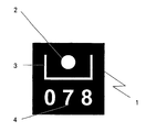
- Such a measuring mark 1 is shown (enlarged) in FIG. It contains measuring characteristics 2, in the form of a circular area, orientation features 3, in the form of a Us, in the center of which are the measuring features and the connecting web clearly is longer than the side bars, and coding features 4, in the form of three digits uniform size, which is at a fixed distance below the connecting bridge of the Us are located.
- the tagged object is made with an optical digital camera various positions recorded as gray scale image. Using 3-D correspondence analysis the 3-D coordinates of the object are related to the pixel coordinates an image of the object.
- potential measuring marks are determined. It can are actual measuring marks or supposed measuring marks, for example reflections or other bright disturbances. For this potential Measurement marks determine the pixel coordinates of their centers. Below is a Procedure for the detection of measuring marks carried out.
- the procedure for the detection of measuring marks is first the environment binarized the known pixel coordinates of the center of a potential target.
- the known pixel coordinates For this purpose, starting from the known pixel coordinates, first the measuring feature, So the circular area determined.
- the circular area of an actual measuring mark is white, so it has a high gray scale, which in the scale used here in the Near 255 must lie.
- Starting from the known pixel coordinates of the Measure the diameter of the circular area in the horizontal and vertical directions and that Result averaged, whereby as limit of the circle surface a decrease of the gray value of the currently, pixels are compared to the gray value of the central pixel by 50 Percent is viewed.
- the environment is now an area of 10 times the diameter considered the measuring circle and the same center. Within this environment the gray values of all pixels are averaged and with this mean value as a threshold value a binarization of the environment is carried out.
- the averaging of the gray values for the determination of the threshold value of the binarization This is done as follows: First, within the environment, the pixel coordinates the center of the supposed or actual measuring mark the maximum and the minimum gray value of the pixels is determined. After that, every pixel within this environment, whose gray value is closer to the maximum gray value of all pixels within this environment lies within the minimum gray level of all the pixels within This environment is assigned to a group of pixels with high gray values. Pixels whose gray value is exactly between the maximum and minimum gray value, are also assigned to this group. Every pixel within this environment, its gray value closer to the minimum gray value of all pixels within that environment is greater than the maximum gray scale of all pixels within that environment, is assigned to a group of pixels with low gray values.
- each pixel within that environment gets its Gray value is above the threshold or equal to the threshold, the binary value White, and every pixel within that environment, its color or gray value below is the threshold, receives the binary value black.
- connectivity areas are searched for, such that all adjoining pixels that know or after binarization are black, assigned to a respective context area.
- a simplified representation of the found contexts creates, in particular a contour representation by means of polygons, a polygon representation. Then this original polygon representation is approximated by an approximate one Polygon representation, a polygon approximation, is replaced. This polygon approximation is carried out in such a way that it uses only support points of the original polygon of the contour representation removed and that while until one predetermined maximum tolerable surface deviation is exceeded.
- the longest is the connecting bridge of the Us assigned as well as each other polygon section, which is relative to the first is within a predetermined angular tolerance range.
- Polygon sections become the weighted average of their angles relative to the major axes of the pixel coordinate system.
- Polygon sections are assigned to the longest of the sidewalls of the Us as well as each another polygon section, which is relative to the first within a given Angle tolerance range is located.
- the polygon sections thus found becomes the weighted average of their angles relative to the major axes of the pixel coordinate system calculated.
- the rotation angle of the measurement mark is calculated and rotational normalization of the image of the measurement mark is performed.
- the supposed shear angle of the measuring mark is calculated and From this supposed shear angle is determined by knowledge of the rotation angle of the actual shear angle calculated and a shear normalization of the image of the measuring mark carried out.
- Each context area identified as a carrier of coding features size is normalized to a 16 by 16 grid and is contrast enhanced by a scaling of the gray values of the individual raster elements of the context area over a gray scale range from 0 to 255.
- Each gray value of this 16 by 16 grid becomes a component of a 256-dimensional feature vector of this context and the feature vector thus formed becomes a major axis transformation such that the individual components of the transformed Feature vector according to their importance for a classification in ordered order.
- the first, so important 40 components of this Feature vectors are fed to a single character classification, specifically here a one-step quadratic polynomial classification.
- a probability vector is calculated whose Number of components is equal to the number of possible characters, so here equal to the Number of all digits, that is 10, and its components the probability specify the identification of a specific character class. Then the character class as the correct suspects, their identification with the highest probability if this probability is a predetermined, minimum value exceeds. Will this minimum probability of correct decoding not reached, there is a rejection of the measuring mark.
- the measuring point coordinates are decoded with the associated ones Coding features passed to the method for measuring objects.
- a quality measure of the detection for example, the smallest of the respective Probability values of the correct recognition of the three digits, to be passed.
- the inventive method for object measurement proves in the embodiment this example is particularly suitable for surveying large objects, for example, of motor vehicles.
- the object to be measured not with measuring marks in material form, but that light by appropriately shaped Masks is projected onto the object surface or correspondingly shaped measuring marks be imaged directly by means of a laser beam on the object surface.
- Such, purely optical method for providing the object surface with measuring marks would also be the measurement of objects with extremely sensitive surface or very difficult to access surface, even allow the measurement of Liquid surfaces.
Landscapes
- Engineering & Computer Science (AREA)
- Physics & Mathematics (AREA)
- General Physics & Mathematics (AREA)
- Multimedia (AREA)
- Theoretical Computer Science (AREA)
- Image Analysis (AREA)
- Length Measuring Devices By Optical Means (AREA)
- Image Processing (AREA)
- Character Input (AREA)
- Character Discrimination (AREA)
- Testing Of Coins (AREA)
Claims (14)
- Procédé pour l'interprétation d'images avec des marques de repère en vue de la mesure d'objets au moyen d'une mesure d'image,caractérisé en ce quequi comprennent des caractéristiques de dimensions, des caractéristiques d'orientation et des caractéristiques de codage,dans lequel on produit d'abord une représentation numérique, composée de pixels, d'une marque de repère présumée ou réelle au moyen d'ondes électromagnétiques du domaine des longueurs d'onde visibles ou d'un domaine proche,dans lequel les coordonnées des pixels du centre de la marque de repère présumée ou réelle à l'intérieur de la représentation numérique sont connues, etdans lequel on compense automatiquement des influences perturbatrices géométriques en ce qui concerne la perceptibilité de la marque de repère à l'aide des caractéristiques d'orientation,l'on compense automatiquement des influences perturbatrices radiométriques par une binarisation locale, etl'on compense automatiquement des influences perturbatrices par des masquages partiels, par le fait que les éléments de trame du domaine de cohérence contenant les caractéristiques de codage de la marque de repère sont soumis à une classification, les probabilités les plus élevées fournies par la classification étant comparées à une probabilité minimale prédéterminée et, en cas de franchissement de cette probabilité minimale, la marque de repère étant associée à la classe d'objets correspondant à la caractéristique de codage la plus probable, etl'on détermine au moins une mesure de qualité pour la reconnaissance de la marque de repère, etl'on effectue au moins un contrôle de reconnaissance d'une marque de repère réelle ou de rejet d'une marque de repère présumée à l'aide de la au moins une mesure de qualité, etl'on déduit des caractéristiques de codage d'une marque de repère réelle un vecteur caractéristique de caractéristiques, qui est introduit dans une classification, etles marques de repère à reconnaítre présentent des caractéristiques de dimensions, des caractéristiques d'orientation et des caractéristiques de codage spatialement distinctes les unes des autres.
- Procédé suivant la revendication 1, caractérisé en ce quel'on binarise d'abord localement la représentation numérique de la marque de repère présumée ou réelle, etl'on n'effectue une compensation d'influences perturbatrices, un contrôle d'au moins un critère de rejet et la déduction du vecteur de caractéristiques d'une marque de repère réelle qu'après cette binarisation.
- Procédé suivant la revendication 2, caractérisé en ce que l'on opère la binarisation locale de telle manière queon détermine la valeur de couleur ou la valeur de gris maximale et minimale des pixels à l'intérieur d'un environnement prédéterminé des coordonnées des pixels du centre de la marque de repère présumée ou réelle, et quechaque pixel à l'intérieur de cet environnement, dont la valeur de couleur ou de gris est plus proche de la valeur maximale de couleur ou de gris de tous les pixels à l'intérieur de cet environnement que de la valeur minimale de couleur ou de gris de tous les pixels à l'intérieur de cet environnement, ou dont la valeur de couleur ou de gris se situe exactement au milieu de ces deux valeurs, est associé à un groupe de pixels avec de hautes valeurs de couleur ou dé gris, et quechaque pixel à l'intérieur de cet environnement, dont la valeur de couleur ou de gris est plus proche de la valeur minimale de couleur ou de gris de tous les pixels à l'intérieur de cet environnement que de la valeur maximale de couleur ou de gris de tous les pixels à l'intérieur de cet environnement, est associé à un groupe de pixels avec de basses valeurs de couleur ou de gris, et queon forme la valeur moyenne de toutes les valeurs de couleur ou de gris de tous les pixels du groupe de pixels avec de hautes valeurs de couleur ou de gris et on la pondère avec le nombre des éléments du groupe, et queon forme la valeur moyenne de toutes les valeurs de couleur ou de gris de tous les pixels du groupe de pixels avec de basses valeurs de couleur ou de gris et on la pondère avec le nombre des éléments du groupe, et queon forme à partir de ces deux valeurs moyennes pondérées une valeur moyenne, qui est utilisée comme valeur de seuil de la binarisation, et quechaque pixel à l'intérieur de cet environnement, dont la valeur de couleur ou de gris est située au-dessus de la valeur de seuil ou est égale à la valeur de seuil, reçoit la valeur binaire Blanc, et quechaque pixel à l'intérieur de cet environnement, dont la valeur de couleur ou de gris est située en dessous de la valeur de seuil, reçoit la valeur binaire Noir.
- Procédé suivant l'une quelconque des revendications 1, 2 ou 3, caractérisé en ce queles caractéristiques de dimensions, les caractéristiques d'orientation et les caractéristiques de codage de la marque de repère sont présentes en nombre fixe connu, et queles caractéristiques de dimensions, les caractéristiques d'orientation et les caractéristiques de codage possèdent les unes par rapport aux autres des relations géométriques fixes connues, en particulier des distances fixes connues et des positions relatives fixes connues les unes par rapport aux autres, et se trouvent dans un rapport de grandeur fixe connu les unes par rapport aux autres, et queon identifie des domaines de cohérence à l'intérieur de la représentation numérique de la marque de repère présumée ou réelle, et queon décide, à l'aide de ces domaines de cohérence, s'il s'agit pour l'objet examiné d'une marque de repère présumée ou d'une marque de repère réelle, et queon prend la décision à l'aide des domaines de cohérence, de savoir s'il s'agit pour l'objet examiné d'une marque de repère présumée ou d'une marque de repère réelle, en contrôlant si les domaines de cohérence individuels trouvés présentent le nombre minimal prédéterminé et se trouvent dans la relation géométrique connue l'un par rapport à l'autre à l'intérieur d'un domaine de tolérances prédéterminé, de préférence prédéterminé librement, et quedans le cas où les domaines de cohérence sont associés à une perturbation, donc à une marque de repère présumée, il se produit un rejet, et quedans le cas où les domaines de cohérence sont associés à une marque de repère réelle, on opère une liaison claire pour chaque domaine de cohérence individuel, de telle manière que l'on sache quel domaine de cohérence individuel est porteur de caractéristiques de dimensions et/ou de caractéristiques d'orientation et/ou de caractéristiques de codage.
- Procédé suivant la revendication 4, caractérisé en ce que l'identification des domaines de cohérence est effectuée de telle manière queon effectue une analyse de cohérence d'objets de valeurs de couleur de la représentation numérique de la marque de repère présumée ou réelle, dans laquelle on associe à un objet de valeur de couleur tous les pixels de la représentation numérique, dont la valeur de couleur est située à l'intérieur d'un domaine de valeurs prédéterminé, ou queon effectue une analyse de cohérence d'objets de valeurs de gris de la représentation numérique de la marque de repère présumée ou réelle, dans laquelle on associe à un objet de valeur de gris tous les pixels de la représentation numérique, dont la valeur de gris est située à l'intérieur d'un domaine de valeurs prédéterminé, ou queon effectue une analyse de cohérence d'objets Noirs et/ou Blancs de la représentation numérique binarisée de la marque de repère présumée ou réelle.
- Procédé suivant la revendication 4, caractérisé en ce que l'identification des domaines de cohérence est effectuée de telle manière queon effectue une analyse de cohérence d'objets de valeurs de couleur de la représentation numérique de la marque de repère présumée ou réelle, dans laquelle on associe à un objet de valeur de couleur tous les pixels de la représentation numérique au moyen d'une classification de la valeur de couleur, de préférence en tenant compte de la valeur de couleur dans un voisinage local, ou queon effectue une analyse de cohérence d'objets de valeurs de gris de la représentation numérique de la marque de repère présumée ou réelle, dans laquelle on associe à un objet de valeur de gris tous les pixels de la représentation numérique au moyen d'une classification de la valeur de gris, de préférence en tenant compte de la valeur de gris dans un voisinage local, ou queon effectue une analyse de cohérence d'objets Noirs et/ou Blancs de la représentation numérique binarisée de la marque de repère présumée ou réelle.
- Procédé suivant l'une quelconque des revendications 3 à 6, caractérisé en ce queon produit une représentation simplifiée des domaines de cohérence trouvés, par une représentation des contours au moyen de polygones, une représentation polygonale, et queon remplace cette représentation polygonale originelle par une représentation polygonale approchée, une approximation polygonale, et queon effectue cette approximation polygonale de telle manière qu'elle écarte exclusivement des sommets du polygone originel de la représentation des contours, notamment jusqu'à ce qu'un écart de surface maximal tolérable prédéterminé, de préférence librement prédéterminé, soit dépassé.
- Procédé suivant l'une quelconque des revendications 4 à 7, caractérisé en ce queon identifie au moins un domaine de cohérence comme support de caractéristiques d'orientation à partir de la quantité des domaines de cohérence trouvés d'une marque de repère réelle, au moyen de la connaissance de la relation géométrique des divers domaines de cohérence les uns par rapport aux autres, et queon détermine l'orientation réelle de la marque de repère à partir de ces caractéristiques d'orientation, et queon opère une normalisation sur une orientation unitaire fixement prédéterminée,
en particulier une normalisation de la représentation numérique de la marque de repère ou des domaines de cohérence, de préférence une normalisation de la représentation des domaines de cohérence, et queon identifie au moins un domaine de cohérence comme support de caractéristiques de codage à partir de la quantité des domaines de cohérence trouvés, au moyen de la connaissance de la relation géométrique des divers domaines de cohérence les uns par rapport aux autres, et quechaque domaine de cohérence, qui a été identifié comme support de caractéristiques de codage, est normalisé en grandeur à une trame n x n, de préférence une trame 16 x 16, et quede préférence chaque domaine de cohérence, qui a été identifié comme support de caractéristiques de codage, est renforcé en contraste par une gradation des valeurs de couleur ou de gris des éléments de trame individuels du domaine de cohérence sur un domaine maximal de valeurs de couleur ou un domaine maximal de valeurs de gris, de préférence sur un domaine de valeurs de gris de 0 à 255, et quechaque valeur de couleur ou de gris d'un élément de trame d'un domaine de cohérence, qui a été identifié comme support de caractéristiques de codage, est utilisé comme composante d'un vecteur de caractéristiques à n x n dimensions, de préférence à 256 dimensions, de ce domaine de cohérence, et quece vecteur de caractéristiques est soumis à une transformation des axes principaux, de telle manière que les composantes individuelles du vecteur de caractéristiques transformé se trouvent en une série ordonnée en fonction de leur importance pour une classification, et queun nombre limité de composantes du vecteur de caractéristiques transformé, compté à partir de la première et donc plus importante composante, de préférence les 40 premières composantes, est introduit dans une classification d'objets individuels, de préférence une classification de signes individuels ou de symboles individuels, de préférence dans une classification de polynômes carrée à un étage, et queau moyen de cette classification, on calcule un vecteur de probabilité, dont le nombre de composantes est égal au nombre des objets de codage possibles, de préférence égal au nombre des signes de codage ou des symboles de codage possibles, et dont les composantes indiquent la probabilité de l'identification d'une classe d'objets déterminée, de préférence la probabilité de l'identification d'une classe de signes ou de symboles déterminée, et quela classe d'objets, de préférence la classe de signes ou de symboles, dont l'identification a été effectuée avec la plus grande probabilité, est supposée correcte, dans la mesure où cette probabilité dépasse une valeur minimale prédéterminée, de préférence librement prédéterminée, et queon opère un rejet de la marque de repère, lorsqu'aucune classe d'objets, de préférence aucune classe de signes ou de symboles, n'a été identifiée avec une probabilité dépassant la probabilité minimale prédéterminée. - Procédé suivant l'une quelconque des revendications 1 à 8, caractérisé en ce queles marques de repère à interpréter présententdes caractéristiques de dimensions,des caractéristiques d'orientation dans au moins deux directions préférées, de préférence dans des directions préférées orientées perpendiculairement l'une à l'autre,des caractéristiques de codage sous la forme d'un nombre fixe de signes et/ou de symboles connus,
et queles caractéristiques de dimensions, les caractéristiques d'orientation et les caractéristiques de codage sont présentes en un nombre fixe connu,
et queles caractéristiques de dimensions, les caractéristiques d'orientation et les caractéristiques de codage présentent des relations géométriques fixes connues les unes par rapport aux autres,
en particulier des distances fixes connues et des positions relatives fixes connues les unes par rapport aux autres, et se trouvent dans un rapport de grandeur fixe connu les unes par rapport aux autres. - Procédé suivant l'une quelconque des revendications 1 à 9, caractérisé en ce queles caractéristiques de dimensions se présentent sous la forme d'une surface circulaire, et queles caractéristiques d'orientation se présentent sous la forme d'une structure en forme de U, se composant de deux parties latérales et d'une âme de jonction, de préférence nettement plus longue, placée perpendiculairement à celles-ci, et queles caractéristiques de codage se présentent sous la forme detrois chiffres successifs d'une police de caractères linéale ouquatre signes successifs tirés des 10 chiffres et des 26 caractères majuscules d'une police de caractères linéale, et queles caractéristiques de dimensions, les caractéristiques d'orientation et les caractéristiques de codage sont disposées les unes par rapport aux autres dans une relation géométrique fixe connue, de telle manière queles caractéristiques de dimensions se trouvent sous la forme d'une surface circulaire au centre à l'intérieur de la structure en forme de U des caractéristiques d'orientation, et queles caractéristiques de codage sont disposées l'une derrière l'autre sous la forme d'un nombre fixe de signes connus sous l'âme de jonction du U à une distance fixe connue et dans un rapport de grandeur fixe connu par rapport à celui-ci.
- Procédé suivant la revendication 10, caractérisé en ce queon recherche des domaines de cohérence dans l'environnement des coordonnées de pixels connues du centre d'une marque de repère présumée ou réelle, et queon détermine pour chaque domaine de cohérence trouvé d'une marque de repère présumée ou réelle un rectangle, qui est le plus petit rectangle parallèle aux axes et entourant le domaine de cohérence respectif, et queon identifie le plus petit domaine de cohérence, à l'intérieur du rectangle circonscrit duquel se trouvent les coordonnées de pixels connues du centre de la marque de repère présumée ou réelle, comme le domaine de cohérence qui contient les caractéristiques de dimensions, et queon identifie le domaine de cohérence suivant en grandeur, à l'intérieur du rectangle circonscrit duquel se trouvent les coordonnées de pixels connues du centre de la marque de repère présumée ou réelle, comme le domaine de cohérence qui contient les caractéristiques d'orientation, et queà l'aide des rectangles circonscrits, on prend la décision de savoir s'il s'agit pour l'objet examiné d'une marque de repère présumée ou réelle, par le fait que l'on contrôle si les deux rectangles se trouvent dans une relation géométrique connue l'un par rapport à l'autre à l'intérieur d'un domaine de tolérances prédéterminé, de préférence librement prédéterminé, de préférence s'ils se trouvent dans un rapport de grandeur connu l'un par rapport à l'autre et/ou si l'un est entouré par l'autre, et queon opère un rejet de la marque de repère si ce domaine de tolérances est dépassé, et quedans le cas de la reconnaissance de l'objet examiné comme une marque de repère réelle, on effectue la détermination de son orientation de telle manière queon produit une approximation polygonale des caractéristiques d'orientation, et queon détermine les angles des caractéristiques d'orientation par rapport aux axes principaux du système de coordonnées de pixels, parou quele report des portions de polygone individuelles pondérées avec leur longueur de l'approximation polygonale dans un histogramme d'angles, et parla détermination des deux amplitudes les plus grandes de cet histogramme d'angles, et parl'attribution de la plus grande amplitude à l'âme de jonction du U, et parl'attribution de la seconde plus grande amplitude aux branches latérales du U,on détermine les angles des caractéristiques d'orientation par rapport aux axes principaux du système de coordonnées de pixels de préférence paret quel'attribution de la plus longue portion de polygone à l'âme de jonction du U, et parl'attribution de toutes les autres portions de polygone à l'âme de jonction du U à l'intérieur d'un domaine de tolérances angulaires prédéterminé, de préférence librement prédéterminé, et parle calcul de la moyenne pondérée des angles de ces portions de polygone,on calcule l'angle de rotation de la marque de repère à partir de la connaissance de l'angle de l'âme de jonction du U par rapport aux axes principaux du système de coordonnées de pixels, et on effectue une normalisation de la rotation de la représentation de la marque de repère, et queon calcule l'angle de cisaillement présumé de la marque de repère à partir de la connaissance de l'angle des branches latérales du U par rapport aux axes principaux du système de coordonnées de pixels et on calcule l'angle de cisaillement réel à partir de cet angle de cisaillement présumé au moyen de la connaissance de l'angle de rotation et on effectue une normalisation du cisaillement de la représentation de la marque de repère, et queon identifie les domaines de cohérence des caractéristiques de codage dans la représentation normalisée en rotation et en cisaillement de la marque de repère, de telle manière queils se trouvent dans le nombre connu en dessous de l'âme de jonction du U, et queleurs différences de grandeur se situent à l'intérieur d'un domaine de tolérances prédéterminé, de préférence librement prédéterminé, et queon opère un rejet de la marque de repère en cas de non respect de ces conditions d'identification.
- Procédé pour la mesure d'un objet, dans lequelcaractérisé en ce quel'objet à mesurer est pourvu de marques de repère, contenant des caractéristiques de dimensions, des caractéristiques d'orientation et des caractéristiques de codage, eton produit une représentation numérique, composée de pixels, de l'objet à mesurer pourvu de marques de repère, au moyen d'ondes électromagnétiques du domaine des longueurs d'onde visibles ou d'un domaine proche, eton identifie des marques de repère potentielles, donc présumées ou réelles, à l'intérieur de la représentation numérique, composée de pixels, de l'objet, et on détermine les coordonnées de pixels des centres de ces marques de repère potentielles,on utilise un procédé pour l'interprétation de marques de repère suivant une ou plusieurs des revendications précédentes, et queon effectue l'interprétation des marques de repère localement à l'intérieur de l'environnement des coordonnées de pixels des centres de ces marques de repère potentielles, et queles coordonnées de pixels des marques de repère individuelles reconnues sont mises en relation avec un système de coordonnées en 3 D de l'objet à mesurer, de préférence mises en relation au moyen d'une analyse de correspondance en 3 D.
- Marque de repère à utiliser dans un procédé pour mesurer un objet,caractérisée en ce quequi présente des caractéristiques de dimensions, des caractéristiques d'orientation et des caractéristiques de codage, dans laquelleles caractéristiques d'orientation présentent au moins deux directions préférées orientées perpendiculairement l'une à l'autre, et dans laquelleles caractéristiques de codage se présentent sous la forme d'un nombre fixe de signes et/ou de symboles connus,dans laquelle les caractéristiques de dimensions, les caractéristiques d'orientation et les caractéristiques de codage sont présentes en un nombre fixe connu,dans laquelle les caractéristiques de dimensions, les caractéristiques d'orientation et les caractéristiques de codage présentent des relations géométriques fixes connues les unes par rapport aux autres,les caractéristiques de dimensions, les caractéristiques d'orientation et les caractéristiques de codage sont spatialement distinctes les unes des autres.
- Marque de repère suivant la revendication 13,
caractérisée en ce queles caractéristiques de dimensions se présentent sous la forme d'une surface circulaire, et queles caractéristiques d'orientation se présentent sous la forme d'une structure en forme de U, se composant de deux parties latérales et d'une âme de jonction, de préférence nettement plus longue, placée perpendiculairement à celles-ci, et queles caractéristiques de codage se présentent sous la forme detrois chiffres successifs d'une police de caractères linéale ouquatre signes successifs tirés des 10 chiffres et des 26 caractères majuscules d'une police de caractères linéale, et queles caractéristiques de dimensions, les caractéristiques d'orientation et les caractéristiques de codage sont disposées les unes par rapport aux autres dans une relation géométrique fixe connue, de telle manière queles caractéristiques de dimensions se trouvent sous la forme d'une surface circulaire au centre à l'intérieur de la structure en forme de U des caractéristiques d'orientation, et queles caractéristiques de codage sont disposées l'une derrière l'autre sous la forme d'un nombre fixe de signes connus sous l'âme de jonction du U à une distance fixe connue et dans un rapport de grandeur fixe connu par rapport à celui-ci.
Applications Claiming Priority (3)
| Application Number | Priority Date | Filing Date | Title |
|---|---|---|---|
| DE19728513 | 1997-07-04 | ||
| DE19728513A DE19728513A1 (de) | 1997-07-04 | 1997-07-04 | Meßmarke und Verfahren zur Erkennung von Meßmarken sowie Verfahren zur Objektvermessung |
| PCT/EP1998/003910 WO1999001841A1 (fr) | 1997-07-04 | 1998-06-26 | Marque de repere, procede de reconnaissance de marques de repere et procede de mesure d'objets |
Publications (2)
| Publication Number | Publication Date |
|---|---|
| EP0993651A1 EP0993651A1 (fr) | 2000-04-19 |
| EP0993651B1 true EP0993651B1 (fr) | 2003-01-08 |
Family
ID=7834587
Family Applications (1)
| Application Number | Title | Priority Date | Filing Date |
|---|---|---|---|
| EP98939536A Expired - Lifetime EP0993651B1 (fr) | 1997-07-04 | 1998-06-26 | Marque de repere, procede de reconnaissance de marques de repere et procede de mesure d'objets |
Country Status (9)
| Country | Link |
|---|---|
| US (1) | US6917720B1 (fr) |
| EP (1) | EP0993651B1 (fr) |
| JP (1) | JP4933689B2 (fr) |
| AT (1) | ATE230866T1 (fr) |
| AU (1) | AU8801398A (fr) |
| CA (1) | CA2295222A1 (fr) |
| DE (2) | DE19728513A1 (fr) |
| ES (1) | ES2189219T3 (fr) |
| WO (1) | WO1999001841A1 (fr) |
Cited By (1)
| Publication number | Priority date | Publication date | Assignee | Title |
|---|---|---|---|---|
| DE102012000609A1 (de) | 2012-01-14 | 2013-07-18 | Daimler Ag | Messmarke und Messverfahren zur Vermessung eines Bauteils mit reflektierender Oberfläche |
Families Citing this family (29)
| Publication number | Priority date | Publication date | Assignee | Title |
|---|---|---|---|---|
| DE29924323U1 (de) | 1999-03-24 | 2002-12-05 | ANITRA Medienprojekte GmbH, 81677 München | Träger für Muster und Lesegerät zur Positionsbestimmung |
| DE19921778A1 (de) * | 1999-03-24 | 2000-10-05 | Anitra Medienprojekte Gmbh | Verfahren, Träger für Muster und Lesegerät zur zweidimensionalen Positionsbestimmung auf Flächen und zur zugehörigen Auslösung von Programmprozessen |
| ES2166275B1 (es) * | 1999-07-30 | 2003-04-01 | Univ Zaragoza | Sistema optico de medida de chasis de vehiculos. |
| EP1174681A3 (fr) * | 2000-06-23 | 2003-01-02 | Ford Global Technologies, Inc. | Méthode et dispositif pour la détermination des contours de flans de tôles |
| US20020094189A1 (en) * | 2000-07-26 | 2002-07-18 | Nassir Navab | Method and system for E-commerce video editing |
| DE10050892A1 (de) * | 2000-10-13 | 2002-05-08 | Dieter Dirksen | Vorrichtung und Verfahren zur automatisierten Registrierung topometrischer Mehrfachaufnahmen |
| DE10112732C2 (de) * | 2001-03-14 | 2003-02-06 | Boochs Frank | Verfahren zur Bestimmung der Lage von Meßbildern eines Objektes relativ zum Objekt |
| DE10119884A1 (de) * | 2001-04-24 | 2002-10-31 | Mueller Umwelttechnik | Meßhut, insbesondere zum Vermessen von Kanalschächten |
| DE10137817B4 (de) * | 2001-08-06 | 2005-10-06 | Institut für Automation & Kommunikation e.V. | Vorrichtung und Verfahren zur Erkennung von optischen Markierungen |
| JP3733075B2 (ja) * | 2002-02-07 | 2006-01-11 | 株式会社国際電気通信基礎技術研究所 | インタラクション・メディアシステム |
| JP2004310330A (ja) * | 2003-04-04 | 2004-11-04 | Sony Corp | プログラム、その方法およびその装置 |
| US7701489B1 (en) | 2003-05-27 | 2010-04-20 | Apple Inc. | Method and apparatus for color correction |
| US7369699B1 (en) * | 2003-08-29 | 2008-05-06 | Apple Inc. | Methods and apparatuses for restoring color and enhancing electronic images |
| US8462384B2 (en) * | 2004-09-29 | 2013-06-11 | Apple Inc. | Methods and apparatuses for aesthetically enhanced image conversion |
| CH698140B1 (de) * | 2006-01-20 | 2009-05-29 | Alstom Technology Ltd | Verfahren zur Digitalisierung dreidimensionaler Bauteile. |
| CN101390129A (zh) * | 2006-02-28 | 2009-03-18 | 仁爱米拉索莱有限公司 | 用于分析对象聚群的方法和设备 |
| JP4807618B2 (ja) * | 2006-03-06 | 2011-11-02 | 富士ゼロックス株式会社 | 画像処理装置及び画像処理プログラム |
| US7557936B2 (en) * | 2006-04-12 | 2009-07-07 | Toyota Motor Engineering & Manufacturing North America, Inc. | Digitizer adapter |
| DE102007039077A1 (de) * | 2007-08-19 | 2009-03-05 | Fachhochschule Gießen-Friedberg | Signalmarken und Verfahren zur photogrammetrischen Vermessung von geometrisch unregelmäßigen Objekten |
| DE102009032771B4 (de) | 2009-07-10 | 2017-06-29 | Gom Gmbh | Messeinrichtung und Verfahren zum dreidimensionalen optischen Vermessen von Objekten |
| JP4856222B2 (ja) * | 2009-08-28 | 2012-01-18 | 照明 與語 | 3次元形状測定方法 |
| CN102930127A (zh) * | 2011-08-09 | 2013-02-13 | 鸿富锦精密工业(深圳)有限公司 | 量测尺寸颜色列表管理方法及系统 |
| JP6099652B2 (ja) * | 2012-09-05 | 2017-03-22 | パイオニア株式会社 | 撮像装置及び画像処理方法 |
| US9786042B2 (en) * | 2015-01-29 | 2017-10-10 | Honeywell International Inc. | Algorithm for measuring wear pin length using an input image |
| IL282209B2 (en) * | 2016-03-08 | 2025-01-01 | Dust Identity Inc | Method and system for generating unique code from artificial intelligence |
| CN109784331B (zh) * | 2019-01-08 | 2023-07-07 | 河北科技大学 | 基于标志点的棒材端面标记方案及字符图像矫正方法 |
| US11341325B2 (en) * | 2019-09-19 | 2022-05-24 | Palantir Technologies Inc. | Data normalization and extraction system |
| CN114088062B (zh) * | 2021-02-24 | 2024-03-22 | 上海商汤临港智能科技有限公司 | 目标定位方法及装置、电子设备和存储介质 |
| CN120198515B (zh) * | 2025-02-26 | 2025-11-21 | 东莞市丰真检测仪器有限公司 | 参数生成方法、纺织物色牢度计算方法及系统 |
Citations (1)
| Publication number | Priority date | Publication date | Assignee | Title |
|---|---|---|---|---|
| EP0416742A2 (fr) * | 1989-08-03 | 1991-03-13 | Minnesota Mining And Manufacturing Company | Articles d'identification de véhicules réfléchissants avec lisibilité mécanique améliorée |
Family Cites Families (13)
| Publication number | Priority date | Publication date | Assignee | Title |
|---|---|---|---|---|
| US3885229A (en) * | 1972-10-28 | 1975-05-20 | Nippon Electric Co | Document scanning apparatus |
| US4776464A (en) * | 1985-06-17 | 1988-10-11 | Bae Automated Systems, Inc. | Automated article handling system and process |
| US4924078A (en) * | 1987-11-25 | 1990-05-08 | Sant Anselmo Carl | Identification symbol, system and method |
| JPH081291Y2 (ja) * | 1989-08-11 | 1996-01-17 | 三井精機工業株式会社 | 高剛性ハイブリッド直線形ボールベアリング |
| FR2657982B1 (fr) * | 1990-02-02 | 1992-11-27 | Cga Hbs | Procede de localisation d'adresse sur des articles a trier, etiquette d'adressage et dispositif de mise en óoeuvre du procede. |
| US5189292A (en) * | 1990-10-30 | 1993-02-23 | Omniplanar, Inc. | Finder pattern for optically encoded machine readable symbols |
| US5726435A (en) * | 1994-03-14 | 1998-03-10 | Nippondenso Co., Ltd. | Optically readable two-dimensional code and method and apparatus using the same |
| US5515447A (en) * | 1994-06-07 | 1996-05-07 | United Parcel Service Of America, Inc. | Method and apparatus for locating an acquisition target in two-dimensional images by detecting symmetry in two different directions |
| ES2122656T3 (es) * | 1994-06-07 | 1998-12-16 | United Parcel Service Inc | Procedimiento y aparato para descodificar simbolos bidimensionales en el dominio espacial. |
| JP2867904B2 (ja) * | 1994-12-26 | 1999-03-10 | 株式会社デンソー | 2次元コード読取装置 |
| US5637849A (en) * | 1995-05-31 | 1997-06-10 | Metanetics Corporation | Maxicode data extraction using spatial domain features |
| JP3060902B2 (ja) * | 1995-06-30 | 2000-07-10 | オムロン株式会社 | 画像処理装置及び画像処理方法 |
| US5764798A (en) * | 1996-03-18 | 1998-06-09 | Intermec Corporation | Prioritized searching methods for finding a coded symbol in a digitized image |
-
1997
- 1997-07-04 US US09/445,914 patent/US6917720B1/en not_active Expired - Fee Related
- 1997-07-04 DE DE19728513A patent/DE19728513A1/de not_active Withdrawn
-
1998
- 1998-06-26 DE DE59806873T patent/DE59806873D1/de not_active Expired - Fee Related
- 1998-06-26 CA CA002295222A patent/CA2295222A1/fr not_active Abandoned
- 1998-06-26 ES ES98939536T patent/ES2189219T3/es not_active Expired - Lifetime
- 1998-06-26 EP EP98939536A patent/EP0993651B1/fr not_active Expired - Lifetime
- 1998-06-26 AU AU88013/98A patent/AU8801398A/en not_active Abandoned
- 1998-06-26 JP JP50628099A patent/JP4933689B2/ja not_active Expired - Fee Related
- 1998-06-26 WO PCT/EP1998/003910 patent/WO1999001841A1/fr not_active Ceased
- 1998-06-26 AT AT98939536T patent/ATE230866T1/de not_active IP Right Cessation
Patent Citations (1)
| Publication number | Priority date | Publication date | Assignee | Title |
|---|---|---|---|---|
| EP0416742A2 (fr) * | 1989-08-03 | 1991-03-13 | Minnesota Mining And Manufacturing Company | Articles d'identification de véhicules réfléchissants avec lisibilité mécanique améliorée |
Non-Patent Citations (1)
| Title |
|---|
| "REGISTRATION MARKS FOR MACHINE VISION.", RESEARCH DISCLOSURE., MASON PUBLICATIONS, HAMPSHIRE., GB, no. 349., 1 May 1993 (1993-05-01), GB, pages 292., XP000377191, ISSN: 0374-4353 * |
Cited By (1)
| Publication number | Priority date | Publication date | Assignee | Title |
|---|---|---|---|---|
| DE102012000609A1 (de) | 2012-01-14 | 2013-07-18 | Daimler Ag | Messmarke und Messverfahren zur Vermessung eines Bauteils mit reflektierender Oberfläche |
Also Published As
| Publication number | Publication date |
|---|---|
| JP2002508069A (ja) | 2002-03-12 |
| JP4933689B2 (ja) | 2012-05-16 |
| WO1999001841A1 (fr) | 1999-01-14 |
| EP0993651A1 (fr) | 2000-04-19 |
| AU8801398A (en) | 1999-01-25 |
| ES2189219T3 (es) | 2003-07-01 |
| US6917720B1 (en) | 2005-07-12 |
| DE59806873D1 (de) | 2003-02-13 |
| DE19728513A1 (de) | 1999-01-07 |
| CA2295222A1 (fr) | 1999-01-14 |
| ATE230866T1 (de) | 2003-01-15 |
Similar Documents
| Publication | Publication Date | Title |
|---|---|---|
| EP0993651B1 (fr) | Marque de repere, procede de reconnaissance de marques de repere et procede de mesure d'objets | |
| DE69504069T2 (de) | Verfahren und gerät zu dekodierung von zweidimensionalen zeichen im raumbereich | |
| DE3505331C2 (de) | Verfahren und Gerät zur Vermessung des bei der Eindringhärteprüfung in einer Probe hinterlassenen Eindrucks | |
| EP2417561B1 (fr) | Code a deux dimensions et procede | |
| DE69131394T2 (de) | Maschinenlesbares Zeichen mit Mehrfachauflösung | |
| DE60307967T2 (de) | Bildverarbeitungsverfahren für die untersuchung des erscheinungsbildes | |
| EP3290861B1 (fr) | Installation de détection comprenant une unité de détection optique et installation d'automatisation | |
| DE102009051826A1 (de) | Verfahren zum Vergleichen der Ähnlichkeit von 3D-bildlichen Objekten | |
| DE102017001915B4 (de) | Verfahren zum kennzeichenlosen Identifizieren mindestens eines Bauteils sowie zum Rückverfolgen von Bauteilen in einem Produktionsprozess | |
| EP2028605A1 (fr) | Procédé de détection de formes symétriques | |
| WO2002048670A2 (fr) | Dispositif et procede de controle de qualite d'un corps | |
| WO2008077538A1 (fr) | Procédé pour évaluer une image à l'aide de repères d'image | |
| DE102020120887B4 (de) | Verfahren zum erfassen einer einhängeposition eines auflagestegs und flachbettwerkzeugmaschine | |
| EP0484935A2 (fr) | Méthode et dispositif pour lire et identifier l'information réprésentée par des signes, en particulier un code à barres, dans un champs deux-/ou trois-dimensionnel à l'aide d'une caméra vidéo qui est capable de générer un signal vidéo numérique de l'image | |
| DE69728469T2 (de) | Gerät und Verfahren zur Ermittlung der Zeichenlinie mittels vereinfachter Projektionsinformation; Zeichenerkennungsgerät und Verfahren | |
| US5253304A (en) | Method and apparatus for image segmentation | |
| WO2022018019A1 (fr) | Procédé et système ou dispositif pour reconnaître un objet dans une image électronique | |
| DE69427735T2 (de) | Zeichenerkennungsgerät | |
| DE69514735T2 (de) | Verfahren und vorrichtung zur identifizierung der orientierung eines punkt-matrix-kodes auf einem gegenstand | |
| DE10143522A1 (de) | Verfahren und Vorrichtung zum Untersuchen eines Objekts | |
| EP1897067B1 (fr) | Procede et dispositif de detection d'une monnaie par utilisation de son image estampee | |
| WO2002015118A1 (fr) | Procede d'identification automatique d'une structure alignee | |
| DE19632058C1 (de) | Optoelektronisch erfaßbares Identifizierungs- oder Zielelement sowie Verfahren zu seiner Erfassung | |
| DE29724135U1 (de) | Meßmarke | |
| EP3913537B1 (fr) | Procédé de détection des marqueurs optiques |
Legal Events
| Date | Code | Title | Description |
|---|---|---|---|
| PUAI | Public reference made under article 153(3) epc to a published international application that has entered the european phase |
Free format text: ORIGINAL CODE: 0009012 |
|
| 17P | Request for examination filed |
Effective date: 19991215 |
|
| AK | Designated contracting states |
Kind code of ref document: A1 Designated state(s): AT CH DE ES FR GB IT LI |
|
| 17Q | First examination report despatched |
Effective date: 20010516 |
|
| GRAH | Despatch of communication of intention to grant a patent |
Free format text: ORIGINAL CODE: EPIDOS IGRA |
|
| GRAH | Despatch of communication of intention to grant a patent |
Free format text: ORIGINAL CODE: EPIDOS IGRA |
|
| GRAA | (expected) grant |
Free format text: ORIGINAL CODE: 0009210 |
|
| RIN1 | Information on inventor provided before grant (corrected) |
Inventor name: MICHAELIS, MARTIN Inventor name: CAESAR, TORSTEN |
|
| AK | Designated contracting states |
Kind code of ref document: B1 Designated state(s): AT CH DE ES FR GB IT LI |
|
| REF | Corresponds to: |
Ref document number: 230866 Country of ref document: AT Date of ref document: 20030115 Kind code of ref document: T |
|
| REG | Reference to a national code |
Ref country code: GB Ref legal event code: FG4D Free format text: NOT ENGLISH |
|
| REG | Reference to a national code |
Ref country code: CH Ref legal event code: EP |
|
| REF | Corresponds to: |
Ref document number: 59806873 Country of ref document: DE Date of ref document: 20030213 Kind code of ref document: P |
|
| GBT | Gb: translation of ep patent filed (gb section 77(6)(a)/1977) |
Effective date: 20030329 |
|
| REG | Reference to a national code |
Ref country code: ES Ref legal event code: FG2A Ref document number: 2189219 Country of ref document: ES Kind code of ref document: T3 |
|
| ET | Fr: translation filed | ||
| PLBE | No opposition filed within time limit |
Free format text: ORIGINAL CODE: 0009261 |
|
| STAA | Information on the status of an ep patent application or granted ep patent |
Free format text: STATUS: NO OPPOSITION FILED WITHIN TIME LIMIT |
|
| 26N | No opposition filed |
Effective date: 20031009 |
|
| PGFP | Annual fee paid to national office [announced via postgrant information from national office to epo] |
Ref country code: GB Payment date: 20040528 Year of fee payment: 7 |
|
| PGFP | Annual fee paid to national office [announced via postgrant information from national office to epo] |
Ref country code: CH Payment date: 20040602 Year of fee payment: 7 |
|
| PGFP | Annual fee paid to national office [announced via postgrant information from national office to epo] |
Ref country code: AT Payment date: 20040603 Year of fee payment: 7 |
|
| PGFP | Annual fee paid to national office [announced via postgrant information from national office to epo] |
Ref country code: DE Payment date: 20040604 Year of fee payment: 7 |
|
| PGFP | Annual fee paid to national office [announced via postgrant information from national office to epo] |
Ref country code: FR Payment date: 20040609 Year of fee payment: 7 |
|
| PGFP | Annual fee paid to national office [announced via postgrant information from national office to epo] |
Ref country code: ES Payment date: 20040616 Year of fee payment: 7 |
|
| PG25 | Lapsed in a contracting state [announced via postgrant information from national office to epo] |
Ref country code: IT Free format text: LAPSE BECAUSE OF NON-PAYMENT OF DUE FEES;WARNING: LAPSES OF ITALIAN PATENTS WITH EFFECTIVE DATE BEFORE 2007 MAY HAVE OCCURRED AT ANY TIME BEFORE 2007. THE CORRECT EFFECTIVE DATE MAY BE DIFFERENT FROM THE ONE RECORDED. Effective date: 20050626 Ref country code: GB Free format text: LAPSE BECAUSE OF NON-PAYMENT OF DUE FEES Effective date: 20050626 Ref country code: AT Free format text: LAPSE BECAUSE OF NON-PAYMENT OF DUE FEES Effective date: 20050626 |
|
| PG25 | Lapsed in a contracting state [announced via postgrant information from national office to epo] |
Ref country code: ES Free format text: LAPSE BECAUSE OF NON-PAYMENT OF DUE FEES Effective date: 20050627 |
|
| PG25 | Lapsed in a contracting state [announced via postgrant information from national office to epo] |
Ref country code: LI Free format text: LAPSE BECAUSE OF NON-PAYMENT OF DUE FEES Effective date: 20050630 Ref country code: CH Free format text: LAPSE BECAUSE OF NON-PAYMENT OF DUE FEES Effective date: 20050630 |
|
| PG25 | Lapsed in a contracting state [announced via postgrant information from national office to epo] |
Ref country code: DE Free format text: LAPSE BECAUSE OF NON-PAYMENT OF DUE FEES Effective date: 20060103 |
|
| REG | Reference to a national code |
Ref country code: CH Ref legal event code: PL |
|
| PG25 | Lapsed in a contracting state [announced via postgrant information from national office to epo] |
Ref country code: FR Free format text: LAPSE BECAUSE OF NON-PAYMENT OF DUE FEES Effective date: 20060228 |
|
| GBPC | Gb: european patent ceased through non-payment of renewal fee |
Effective date: 20050626 |
|
| REG | Reference to a national code |
Ref country code: FR Ref legal event code: ST Effective date: 20060228 |
|
| REG | Reference to a national code |
Ref country code: ES Ref legal event code: FD2A Effective date: 20050627 |