EP0485076B1 - Garniture - Google Patents
Garniture Download PDFInfo
- Publication number
- EP0485076B1 EP0485076B1 EP91309451A EP91309451A EP0485076B1 EP 0485076 B1 EP0485076 B1 EP 0485076B1 EP 91309451 A EP91309451 A EP 91309451A EP 91309451 A EP91309451 A EP 91309451A EP 0485076 B1 EP0485076 B1 EP 0485076B1
- Authority
- EP
- European Patent Office
- Prior art keywords
- collar
- pipe
- flange
- combination
- lining
- Prior art date
- Legal status (The legal status is an assumption and is not a legal conclusion. Google has not performed a legal analysis and makes no representation as to the accuracy of the status listed.)
- Expired - Lifetime
Links
Images




Classifications
-
- F—MECHANICAL ENGINEERING; LIGHTING; HEATING; WEAPONS; BLASTING
- F16—ENGINEERING ELEMENTS AND UNITS; GENERAL MEASURES FOR PRODUCING AND MAINTAINING EFFECTIVE FUNCTIONING OF MACHINES OR INSTALLATIONS; THERMAL INSULATION IN GENERAL
- F16L—PIPES; JOINTS OR FITTINGS FOR PIPES; SUPPORTS FOR PIPES, CABLES OR PROTECTIVE TUBING; MEANS FOR THERMAL INSULATION IN GENERAL
- F16L23/00—Flanged joints
- F16L23/12—Flanged joints specially adapted for particular pipes
- F16L23/125—Flanged joints specially adapted for particular pipes with an internal or external coating
-
- F—MECHANICAL ENGINEERING; LIGHTING; HEATING; WEAPONS; BLASTING
- F16—ENGINEERING ELEMENTS AND UNITS; GENERAL MEASURES FOR PRODUCING AND MAINTAINING EFFECTIVE FUNCTIONING OF MACHINES OR INSTALLATIONS; THERMAL INSULATION IN GENERAL
- F16L—PIPES; JOINTS OR FITTINGS FOR PIPES; SUPPORTS FOR PIPES, CABLES OR PROTECTIVE TUBING; MEANS FOR THERMAL INSULATION IN GENERAL
- F16L58/00—Protection of pipes or pipe fittings against corrosion or incrustation
- F16L58/18—Protection of pipes or pipe fittings against corrosion or incrustation specially adapted for pipe fittings
- F16L58/187—Protection of pipes or pipe fittings against corrosion or incrustation specially adapted for pipe fittings for flanged joints
Definitions
- This invention relates to a fitting in combination with a pipe lined internally with a compressible lining which protrudes from an end of the pipe.
- DE-A-2 034 185 discloses a combination of the type (hereinafter called the type referred to)in which a fitting is in combination with a compressible lining which protrudes from an end of the pipe, and wherein said fitting comprises a collar provided with a collar flange, said collar being slidably fitted over an external wall of said pipe, a generally cylindrical hollow member extending within the collar and the protruding end of the lining and having an external wall against which the protruding end of the lining is sealingly clamped around the member, said member having a member flange adjacent to said collar to which the flange is clamped using nut and bolt assemblies, said collar flange being adjacent to said member flange, an annular space between the collar and said member and surrounding the member, the protruding end of said lining being exposed to said space, and said space being sealed in a fluid-tight manner from the interior of the lined pipe provided the seal between the member and the lining is fluid-tight.
- DE-A-2 034 185 the collar is a thick ring or tube of fibre-glass and resin bonded to the pipe and the member flange is clamped against an end of the collar without any seal being provided between the member flange and the end face.
- An object of the invention is to provide a combination of the type referred to in which the leak tightness of the seal between the lining and member can be tested independently of the remainder of the pipe.
- Another object is to provide a combination of the type referred to in which the collar is attachable to the pipe without the need for bonding.
- a combination of the type referred to is characterised in that said collar has a first external collar flange and a second external collar flange at opposite respective first and second ends of the collar, an attachment flange is an initial sliding fit over said external wall and is attached to the external wall by a compression fitting comprising said first end of said collar and a first sealing gasket of compressible resilient material surrounding said end of the pipe, said first gasket is compressed between the first end of the collar and the attachment flange to form a seal between said collar and said external wall of said pipe, said first collar flange and said attachment flange are secured together using second nut and bolt assemblies, a second sealing gasket clamped between the member flange and the second collar flange using said first mentioned nut and bolt assemblies, and a wall of the collar is penetrable through to said space whereby the content of said space can be observed so that absence from said space of fluid which is the same as the fluid within the lined pipe will signify a fluid-tight seal between the lining and the member.
- the fitting comprises a collar 1 and a clamping means in the form of a member 2 for use with the collar 1.
- the collar 1 is generally cylindrical in shape and has a first part 3 having an internal wall diameter dimensioned to form a close sliding fit with the external wall 4 of the end of a pipe or pipe section 5 which is lined with a compressible lining 6, the collar 1 having a second part 7 with an internal wall diameter dimensioned to sleeve a part 8 of the lining 6 protruding outwardly from the end of the pipe 5.
- the internal diameter of the first part 3 of the collar 1 is greater than that of the second part 7 for obvious reasons and a junction in the form of a step 9 is formed where the walls adjoin.
- Each end of the collar 1 is formed with circular flanges 10 and 11 respectively, the flange 10 permitting one end of the collar 1 to be bolted by nut and bolt assembles 12 to a sliding flange 13 attached by a compression fitting to the outer wall 4 of the pipe 5 and flange 11 permitting the other end of the collar 1 to be bolted by nut and bolt assemblies 14 to inter alia the flanged end 15 of an adjacent pipe or pipe section 16.
- a flexible circular gasket 17 of rubber or like material is in use as shown positioned around the outer wall 4 of the pipe or pipe section 5, the gasket 17 being compressed between the flanges 10 and 13 to form a seal between the collar 1 and the external wall 4 of the pipe or pipe section 5 upon sufficient tightening of the nut and bolt assemblies 12.
- the member 2 has a generally cylindrical body 20 which is formed with a flange 21 at one end, the external diameter of the body 20 tapering inwardly from the flange 21 to its other end 22.
- the external wall of the member 2 is provided with circumferential indentations 23 extending inwardly from the outer surface of the wall.
- the indentations 23 are arranged as spaced rings along the wall for a purpose to be described.
- the first collar part 3 is fitted over the outer wall 4 of the pipe or pipe section 5 until the wall engages the step 9.
- the cylindrical body 20 of the member 2 is then inserted into the lining part 8, a compressible flat annular gasket 24 of rubber or like material being first positioned around the outer wall of the body 20 so as in use to be compressed between the flanges 11 and 21. Finally the flanges 11 and 21 are bolted to the pipe flange 15 by means of the nut and bolt assemblies 14, a gasket 25 similar to gasket 24 being positioned between the flanges 15 and 21.
- the tapers on the outer wall of the body 20 and on the inner wall of the collar part 7 are matched so that on tightening the assemblies 14 the lining portion 8 is compressed between the body 20 and the part 7 so that a seal is formed between the lining and the collar.
- Corresponding seals are also formed between the flanges 11 and 21 and 21 and 15 by compression of the gaskets 24 and 25.
- the indentations 23 in the surface of the body 20 enable the body 20 to grip the lining portion 8 when the latter is forced by the body 20 against the collar part 7 to form the seal.
- the collar 1 can be connected to the pipe 4 before it is lined.
- the pipe 5 is then lined, part 8 of the lining being allowed to protrude beyond the end of the pipe 5 into the second collar part 7.
- the cylindrical body 20 of the member 2 is inserted into the lining 8 and the member 2 is connected to the pipe 4 so that the lining part 8 is compressed between the body 20 and the collar part 7.
- the collar part 7 in this case mainly serves as a means for connecting the member 2 to the pipe wall 4 but unlike that shown in Figure 1 the collar part 7 in Figure 2 has no taper on its internal wall.
- a clamping means in the form of a ring-like member 26 is provided to clamp the lining portion 8 to the outer portion of the member body 20.
- the member 26 is of spring steel or like resilient material and has a frusto-conical form and in use as will subsequently be described is fitted over the lining portion 8 with its narrower diameter end leading.
- each locking assembly 30 comprises internally threaded bushes 31 and 32, one located on each piece for engagement and alignment to receive a bolt 33 for locking the pieces together by means of a nut 34 after the bolt 33 has been threaded through the aligned bores of the bushes.
- the assembly 30 shown in the Figures lies adjacent an outer edge of the pieces 28 and 29 while a corresponding further assembly lies adjacent a diametrically opposite outer edge of the pieces.
- Each piece 28 and 29 is also provided with through-going apertures 35 and 36 respectively for alignment with corresponding apertures 37 and 38 in the flange 21 of the member 2 to receive drawing bolts 39 and 40 as shown in Figures 6 and 7.
- Nuts 41 and 42 are then located on the bolts 39 and 40 respectively and by tightening the nuts 41 and 42 against the pieces 28 and 29 the pieces 28 and 29 are drawn towards the flange 21 thereby drawing the clamping ring 26 towards the flange 21 and so compressing the lining portion 8 against the body 20 of the member 2.
- there may be two or more drawing bolt/nut assemblies for each piece which are consequently provided with a corresponding number of apertures.
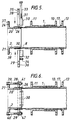
- the fitting may be used to blank off the end of the pipe or pipe section 4 as shown.
- a blanking disc 42 is connected by the nut and bolt assemblies 14 to the flange 21 of the member 3.
- the fitting may be used to connect a first section of a pipe lined with a hose to an adjoining unlined section.
- the fitting may also be used to connect a hose-lined pipe to a further pipe. As just described it may also be used to blank off the end of a hoselined pipe.
- the fitting is suitable for pipes lined with the resin impregnated fabric type of hose, or with polyethylene or similar type plastics materials, such pipes normally being of pit cast, spun or ductile iron and steel, the lining serving to extend the life of an otherwise defunct pipe used for instance as a gas, water or sewage main or for carrying petrochemicals.
- the soundness of the seal between the lining 6 and its clamping member may be tested independently of the rest of the lined pipe by for instance drilling a hole through the collar part 7 into the spaces 43 in Figure 1 and 44 in Figure 2 between the body 20 of the member 2 and the collar part 7. If the seal is sound no gas will be detected issuing through the hole.
Landscapes
- Engineering & Computer Science (AREA)
- General Engineering & Computer Science (AREA)
- Mechanical Engineering (AREA)
- Flanged Joints, Insulating Joints, And Other Joints (AREA)
- Pipe Accessories (AREA)
- Protection Of Pipes Against Damage, Friction, And Corrosion (AREA)
- Joints Allowing Movement (AREA)
Claims (13)
- Raccord en combinaison avec un tuyau (5) comportant intérieurement un revêtement compressible (6) qui est saillant (8) d'une extrémité du tuyau, ledit raccord comprenant un collier (1) équipé d'une bride de collier (11), ledit collier étant ajusté à glissement sur une paroi externe (4) dudit tuyau (5), un élément creux sensiblement cylindrique (2) s'étendant à l'intérieur du collier (1) et de l'extrémité saillante (8) du revêtement (6) et comportant une paroi externe contre laquelle l'extrémité saillante (8) du revêtement (6) est serrée de manière à former un joint autour de l'élément (2), ledit élément (2) comportant une bride d'élément (21) voisine dudit collier (1) sur lequel la bride (21) est serrée a l'aide d'ensembles d'écrou et de vis (14), ladite bride (11) du collier étant voisine de ladite bride (21) de l'élément, un espace annulaire (43, 44) qui est situé entre le collier (1) et ledit élément (2) et entourant l'élément (2), l'extrémité saillante (8) dudit revêtement étant exposée audit espace (43, 44) et ledit, espace (43, 44) étant isolé de manière étanche aux fluides de l'intérieur du tuyau revêtu (5, 6) à condition que le joint entre l'élément (2) et le revêtement (6) soit étanche aux fluides, la combinaison étant caractérisée en ce que ledit collier (1) comprend une première bride externe de collier (10) et une seconde bride externe de collier (11) aux première et seconde extrémités opposées respectives du collier (1), une bride de fixation (13) est initialement placée à ajustement coulissant sur ladite paroi externe (4) et elle est fixée à la paroi externe (4) par un raccord à compression comprenant ladite première extrémité dudit collier (1) et une première garniture d'étanchéité (17) en matière compressible élastique qui entoure ladite extrémité du tuyau (5), ladite première garniture (17) étant comprimée entre la première extrémité du collier (1) et la bride de fixation (13) de manière à former un joint entre ledit collier (1) et ladite paroi externe (4) dudit tuyau (5), ladite première bride (10) du collier et ladite bride de fixation (13) étant fixées l'une à l'autre à l'aide de seconds ensembles d'écrou et de vis (12), une seconde garniture d'étanchéité (24) est serrée entre la bride (21) de l'élément et la seconde bride (11) du collier à l'aide desdits premiers ensembles mentionnés d'écrou et de vis (14) et il est possible de passer par une paroi (7) du collier (1) pour accéder audit espace (43, 44) de manière qu'il soit possible d'observer le contenu dudit espace (43, 44) de façon que l'absence, dans ledit espace, de fluide qui est le même que le fluide se trouvant dans le tuyau revêtu (5, 6) signifie que le joint entre le revêtement (6) et l'élément (2) est étanche aux fluides.
- Combinaison selon la revendication 1, caractérisée en ce que l'élément (2) comprend un corps sensiblement cylindrique (20) ayant une paroi externe s'ajustant l'intérieur de l'extrémité saillante (8) du revêtement (6) et serrant une partie circonférentielle de cette extrémité saillante (8) contre une partie circonférentielle d'une paroi interne du collier (1).
- Combinaison selon la revendication 2, caractérisée en ce que l'élément (2) a un diamètre externe qui se rétrécit en cône vers l'intérieur d'une extrémité vers une extrémité opposée qui est la plus proche de l'extrémité du tuyau (5).
- Combinaison selon la revendication 3, caractérisée en ce que le collier (1) comprend une partie (7) qui a un diamètre interne qui se rétrécit en cône vers l'intérieur sensiblement à partir de ladite seconde extrémité du collier et l'extrémité saillante (8) du revêtement (6) est serrée contre ladite partie (7) par ledit élément (2).
- Combinaison selon l'une quelconque des revendications 1 à 4, caractérisée en ce qu'une ou la paroi externe de l'élément (2) comporte de multiples échancrures (23) orientées vers l'intérieur de la surface extérieure de ladite paroi externe de l'élément (2).
- Combinaison selon la revendication 1, caractérisée en ce que l'extrémité saillant (8) du revêtement (6) est serrée contre l'élément (2) par un organe de serrage (26).
- Combinaison selon la revendication 6, caractérisée en ce que l'organe de serrage consiste en un anneau (26) s'ajustant autour d'une partie circonférentielle du revêtement (6) et la serrant contre une paroi externe de l'élément (2).
- Combinaison selon la revendication 7, caractérisée en ce que l'anneau (26) est en matière élastique.
- Combinaison selon la revendication 7 ou la revendication 8, caractérisée en ce que l'anneau (26) est de forme tronconique et l'extrémité de l'anneau (26) qui a le diamètre le plus petit est la plus proche de l'extrémité du tuyau (5).
- Combinaison selon l'une quelconque des revendications 7 à 9, caractérisée en ce que l'élément (2) a un diamètre externe qui se rétrécit en cône vers l'intérieur d'une extrémité vers une extrémité opposée qui est la plus proche de l'extrémité du tuyau (5).
- Combinaison selon l'une quelconque des revendications 7 à 10, caractérisée en ce qu'une paroi externe de l'élément (2) comporte de multiples échancrures (23) orientées vers l'intérieur de la surface extérieure de ladite paroi externe de l'élément.
- Combinaison selon l'une quelconque des revendications précédentes, caractérisée en ce que les premiers ensembles d'écrou et de vis (14) sont utilisés pour fixer un second tuyau (16) à la bride (21) de l'élément.
- Combinaison selon l'une quelconque des revendications 1 à 5, caractérisée en ce qu'un disque formant un cache (42) est fixé à la bride (21) de l'élément à l'aide des premiers ensembles d'écrou et de vis (14).
Applications Claiming Priority (2)
| Application Number | Priority Date | Filing Date | Title |
|---|---|---|---|
| GB9024290A GB2249599B (en) | 1990-11-08 | 1990-11-08 | A fitting and pipe combination |
| GB9024290 | 1990-11-08 |
Publications (2)
| Publication Number | Publication Date |
|---|---|
| EP0485076A1 EP0485076A1 (fr) | 1992-05-13 |
| EP0485076B1 true EP0485076B1 (fr) | 1994-06-01 |
Family
ID=10685053
Family Applications (1)
| Application Number | Title | Priority Date | Filing Date |
|---|---|---|---|
| EP91309451A Expired - Lifetime EP0485076B1 (fr) | 1990-11-08 | 1991-10-15 | Garniture |
Country Status (6)
| Country | Link |
|---|---|
| US (1) | US5244237A (fr) |
| EP (1) | EP0485076B1 (fr) |
| JP (1) | JPH0769030B2 (fr) |
| DE (1) | DE69102246T2 (fr) |
| ES (1) | ES2054445T3 (fr) |
| GB (1) | GB2249599B (fr) |
Families Citing this family (16)
| Publication number | Priority date | Publication date | Assignee | Title |
|---|---|---|---|---|
| CA2150491C (fr) | 1994-06-23 | 2001-10-02 | Robert E. Klemm | Tuyau presentant un manchon revetu resistant a l'usure et remplacable |
| US5794982A (en) * | 1995-11-06 | 1998-08-18 | Green; Herbert J. | Mechanical pipe joint with liners |
| NO972019L (no) * | 1997-04-30 | 1998-11-02 | Olimb As Kristian | Endeavslutning for r°r |
| US6302449B1 (en) | 1999-10-05 | 2001-10-16 | Matthew Clayton | Sealing ring/sealing nut |
| DE10160379B4 (de) * | 2001-12-10 | 2005-11-10 | Rehau Ag + Co. | Kupplung für Rohre und Verfahren zu ihrem Aufbau |
| US6902205B2 (en) | 2003-01-16 | 2005-06-07 | Flexpipe Systems, Inc. | Coupling for composite pipe |
| CN1308609C (zh) * | 2003-04-15 | 2007-04-04 | 西安理工大学 | 一种自适应自抱紧式密封装置 |
| US20060127622A1 (en) * | 2004-11-24 | 2006-06-15 | Mohan Pidatala K | System of pipes for use in oil wells |
| US7472885B2 (en) * | 2006-03-06 | 2009-01-06 | Honeywell International, Inc. | Compact, lightweight cabin pressure control system butterfly outflow valve with redundancy features |
| US7861743B1 (en) * | 2007-03-16 | 2011-01-04 | Wren Joseph J | Sacrificial conduit lining system |
| US8714597B2 (en) * | 2007-10-08 | 2014-05-06 | United Pipeline Systems, Inc. | Welded joint for lined pipe and components thereof |
| RU2381407C1 (ru) * | 2008-07-01 | 2010-02-10 | Общество с ограниченной ответственностью "ЛУКОЙЛ-ПЕРМЬ" | Способ эксплуатации трубопроводов с фланцевыми соединениями и межфланцевый компенсатор для его осуществления |
| BR112014032301B1 (pt) * | 2012-06-26 | 2022-08-30 | Baker Hughes Energy Technology UK Limited | Tubo flexível para transporte de fluidos a partir de uma localização submarina e seu método de montagem |
| US9377149B2 (en) * | 2013-03-14 | 2016-06-28 | SAK Construction, LLC | Systems and apparatus for inhibiting a compressed pipe liner from retreating into a host pipe |
| KR101291614B1 (ko) | 2013-04-10 | 2013-08-01 | 임채균 | 라이닝공법에 의해 보수된 갱생관의 단부 마감장치 |
| US11873939B2 (en) * | 2020-09-28 | 2024-01-16 | Ina Acquisition Corp. | Pipe liner end termination |
Family Cites Families (11)
| Publication number | Priority date | Publication date | Assignee | Title |
|---|---|---|---|---|
| DE969600C (de) * | 1955-04-01 | 1958-07-03 | Mannesmann Ag | Rohrverbindung fuer Mehrlagenrohre |
| US3210095A (en) * | 1962-03-02 | 1965-10-05 | Phillips Petroleum Co | Plastic lined conduit and method of construction |
| GB1145667A (en) * | 1966-04-19 | 1969-03-19 | Daimler Benz Ag | Improvements relating to plug-in connection fittings for high pressure hose |
| GB1277113A (en) * | 1969-07-16 | 1972-06-07 | Dunlop Holdings Ltd | Assemblies of tubular members |
| US4083583A (en) * | 1976-11-08 | 1978-04-11 | Perfection Corporation | Pipe fitting having a non-metallic sealing member |
| US4064619A (en) * | 1976-12-03 | 1977-12-27 | Zap-Lok Systems International, Inc. | Method of joining plastic coated pipe |
| NL8202232A (nl) * | 1982-06-02 | 1984-01-02 | Wavin Bv | Buisverbinding. |
| US4494776A (en) * | 1983-05-23 | 1985-01-22 | Umc Industries, Inc. | Joint for plastic lined light-weight metal piping |
| US4709946A (en) * | 1987-02-20 | 1987-12-01 | Hunter John J | Lined pipe joint |
| US4805942A (en) * | 1987-08-24 | 1989-02-21 | Stuart Goodridge | Field attachable and reusable hose end fitting for convoluted end |
| US4786757A (en) * | 1987-11-23 | 1988-11-22 | 501 Fleetwood Electronics, Inc. | Flexible electromagnetic pulse shielding conduit |
-
1990
- 1990-11-08 GB GB9024290A patent/GB2249599B/en not_active Expired - Fee Related
-
1991
- 1991-10-15 DE DE69102246T patent/DE69102246T2/de not_active Expired - Fee Related
- 1991-10-15 ES ES91309451T patent/ES2054445T3/es not_active Expired - Lifetime
- 1991-10-15 EP EP91309451A patent/EP0485076B1/fr not_active Expired - Lifetime
- 1991-11-07 JP JP3291705A patent/JPH0769030B2/ja not_active Expired - Fee Related
- 1991-11-08 US US07/787,930 patent/US5244237A/en not_active Expired - Fee Related
Also Published As
| Publication number | Publication date |
|---|---|
| GB2249599A (en) | 1992-05-13 |
| DE69102246T2 (de) | 1994-09-15 |
| GB2249599B (en) | 1994-06-08 |
| JPH0769030B2 (ja) | 1995-07-26 |
| EP0485076A1 (fr) | 1992-05-13 |
| DE69102246D1 (de) | 1994-07-07 |
| JPH04262188A (ja) | 1992-09-17 |
| ES2054445T3 (es) | 1994-08-01 |
| US5244237A (en) | 1993-09-14 |
| GB9024290D0 (en) | 1990-12-19 |
Similar Documents
| Publication | Publication Date | Title |
|---|---|---|
| EP0485076B1 (fr) | Garniture | |
| US5421623A (en) | Friction sealed coupling for pipe | |
| US6595559B1 (en) | Pipe coupling | |
| US5509699A (en) | Mechanical joint pipe adapter with inserted flexible spline | |
| CA2563355C (fr) | Joint de tuyaux mecanique, joint d'etancheite, et procede de blocage de bouts males de tuyaux dans des cloches taraudees de joints de tuyaux mecaniques | |
| US4486036A (en) | Reusable coupling | |
| CA1308042C (fr) | Systeme de rehabilication de tuyaux | |
| US5829793A (en) | Self-restrained adapter system for connecting plastic pipe system to metallic pipe system | |
| US5851037A (en) | Pipe coupling with gasket positioner | |
| US3338598A (en) | Coupling method and devices for lined pipe | |
| US20110233924A1 (en) | Entry boot | |
| US4620731A (en) | Apparatus for sealing pipe flanges | |
| US2653040A (en) | Pipe coupling | |
| US6983960B2 (en) | Mechanical joint bell adapter for polyethylene pipe | |
| JPH0333594A (ja) | 管路用メンテナンス継手機構 | |
| US3070130A (en) | Pipe line repair with resilient bellows sleeve | |
| EP0183510B1 (fr) | Assemblage pour brider un tuyau | |
| EP0459542B1 (fr) | Dispositif de raccordement d'un tuyau souple à paroi mince à un élément tubulaire | |
| US20200248857A1 (en) | Fitting for connecting a main pipe liner to a branch conduit | |
| US4715107A (en) | Method of forming an airspring with pneumatic fitting | |
| GB2282653A (en) | Branch insert | |
| EP0645575A1 (fr) | Raccord de tuyau | |
| US20200132234A1 (en) | Fitting for connecting a main pipe liner to a branch conduit | |
| EP0141680A2 (fr) | Tuyaux revêtus de matière plastique | |
| JPH09250668A (ja) | 離脱防止管継手 |
Legal Events
| Date | Code | Title | Description |
|---|---|---|---|
| PUAI | Public reference made under article 153(3) epc to a published international application that has entered the european phase |
Free format text: ORIGINAL CODE: 0009012 |
|
| AK | Designated contracting states |
Kind code of ref document: A1 Designated state(s): BE DE ES FR GB IT NL |
|
| 17P | Request for examination filed |
Effective date: 19920518 |
|
| 17Q | First examination report despatched |
Effective date: 19920108 |
|
| GRAA | (expected) grant |
Free format text: ORIGINAL CODE: 0009210 |
|
| AK | Designated contracting states |
Kind code of ref document: B1 Designated state(s): BE DE ES FR GB IT NL |
|
| ITF | It: translation for a ep patent filed | ||
| REF | Corresponds to: |
Ref document number: 69102246 Country of ref document: DE Date of ref document: 19940707 |
|
| REG | Reference to a national code |
Ref country code: ES Ref legal event code: FG2A Ref document number: 2054445 Country of ref document: ES Kind code of ref document: T3 |
|
| ET | Fr: translation filed | ||
| PLBE | No opposition filed within time limit |
Free format text: ORIGINAL CODE: 0009261 |
|
| STAA | Information on the status of an ep patent application or granted ep patent |
Free format text: STATUS: NO OPPOSITION FILED WITHIN TIME LIMIT |
|
| 26N | No opposition filed | ||
| REG | Reference to a national code |
Ref country code: GB Ref legal event code: IF02 |
|
| PGFP | Annual fee paid to national office [announced via postgrant information from national office to epo] |
Ref country code: FR Payment date: 20020906 Year of fee payment: 12 |
|
| PGFP | Annual fee paid to national office [announced via postgrant information from national office to epo] |
Ref country code: GB Payment date: 20020916 Year of fee payment: 12 |
|
| PGFP | Annual fee paid to national office [announced via postgrant information from national office to epo] |
Ref country code: NL Payment date: 20020919 Year of fee payment: 12 |
|
| PGFP | Annual fee paid to national office [announced via postgrant information from national office to epo] |
Ref country code: DE Payment date: 20020924 Year of fee payment: 12 |
|
| PGFP | Annual fee paid to national office [announced via postgrant information from national office to epo] |
Ref country code: ES Payment date: 20021007 Year of fee payment: 12 |
|
| PGFP | Annual fee paid to national office [announced via postgrant information from national office to epo] |
Ref country code: BE Payment date: 20021016 Year of fee payment: 12 |
|
| BECH | Be: change of holder |
Owner name: *LATTICE INTELLECTUAL PROPERTY LTD Effective date: 20021209 |
|
| REG | Reference to a national code |
Ref country code: GB Ref legal event code: 732E |
|
| NLT1 | Nl: modifications of names registered in virtue of documents presented to the patent office pursuant to art. 16 a, paragraph 1 |
Owner name: TRANSCO PLC Owner name: BG TRANSCO PLC Owner name: BG PUBLIC LIMITED COMPANY |
|
| PG25 | Lapsed in a contracting state [announced via postgrant information from national office to epo] |
Ref country code: GB Free format text: LAPSE BECAUSE OF NON-PAYMENT OF DUE FEES Effective date: 20031015 |
|
| PG25 | Lapsed in a contracting state [announced via postgrant information from national office to epo] |
Ref country code: ES Free format text: LAPSE BECAUSE OF NON-PAYMENT OF DUE FEES Effective date: 20031016 |
|
| PG25 | Lapsed in a contracting state [announced via postgrant information from national office to epo] |
Ref country code: BE Free format text: LAPSE BECAUSE OF NON-PAYMENT OF DUE FEES Effective date: 20031031 |
|
| NLS | Nl: assignments of ep-patents |
Owner name: LATTICE INTELLECTUAL PROPERTY LIMITED |
|
| BERE | Be: lapsed |
Owner name: *LATTICE INTELLECTUAL PROPERTY LTD Effective date: 20031031 |
|
| PG25 | Lapsed in a contracting state [announced via postgrant information from national office to epo] |
Ref country code: NL Free format text: LAPSE BECAUSE OF NON-PAYMENT OF DUE FEES Effective date: 20040501 Ref country code: DE Free format text: LAPSE BECAUSE OF NON-PAYMENT OF DUE FEES Effective date: 20040501 |
|
| GBPC | Gb: european patent ceased through non-payment of renewal fee |
Effective date: 20031015 |
|
| PG25 | Lapsed in a contracting state [announced via postgrant information from national office to epo] |
Ref country code: FR Free format text: LAPSE BECAUSE OF NON-PAYMENT OF DUE FEES Effective date: 20040630 |
|
| NLV4 | Nl: lapsed or anulled due to non-payment of the annual fee |
Effective date: 20040501 |
|
| REG | Reference to a national code |
Ref country code: FR Ref legal event code: ST |
|
| REG | Reference to a national code |
Ref country code: ES Ref legal event code: FD2A Effective date: 20031016 |
|
| PG25 | Lapsed in a contracting state [announced via postgrant information from national office to epo] |
Ref country code: IT Free format text: LAPSE BECAUSE OF NON-PAYMENT OF DUE FEES;WARNING: LAPSES OF ITALIAN PATENTS WITH EFFECTIVE DATE BEFORE 2007 MAY HAVE OCCURRED AT ANY TIME BEFORE 2007. THE CORRECT EFFECTIVE DATE MAY BE DIFFERENT FROM THE ONE RECORDED. Effective date: 20051015 |