EP0485132A2 - Capteur de direction avec un capteur du magnétisme terrestre et un capteur gyroscopique du vitesse de rotation et système de navigation qui contient ce capteur de direction - Google Patents
Capteur de direction avec un capteur du magnétisme terrestre et un capteur gyroscopique du vitesse de rotation et système de navigation qui contient ce capteur de direction Download PDFInfo
- Publication number
- EP0485132A2 EP0485132A2 EP91310150A EP91310150A EP0485132A2 EP 0485132 A2 EP0485132 A2 EP 0485132A2 EP 91310150 A EP91310150 A EP 91310150A EP 91310150 A EP91310150 A EP 91310150A EP 0485132 A2 EP0485132 A2 EP 0485132A2
- Authority
- EP
- European Patent Office
- Prior art keywords
- sensor
- driving direction
- disturbance
- earth magnetism
- rate gyro
- Prior art date
- Legal status (The legal status is an assumption and is not a legal conclusion. Google has not performed a legal analysis and makes no representation as to the accuracy of the status listed.)
- Granted
Links
Images


Classifications
-
- G—PHYSICS
- G01—MEASURING; TESTING
- G01C—MEASURING DISTANCES, LEVELS OR BEARINGS; SURVEYING; NAVIGATION; GYROSCOPIC INSTRUMENTS; PHOTOGRAMMETRY OR VIDEOGRAMMETRY
- G01C21/00—Navigation; Navigational instruments not provided for in groups G01C1/00 - G01C19/00
- G01C21/26—Navigation; Navigational instruments not provided for in groups G01C1/00 - G01C19/00 specially adapted for navigation in a road network
- G01C21/28—Navigation; Navigational instruments not provided for in groups G01C1/00 - G01C19/00 specially adapted for navigation in a road network with correlation of data from several navigational instruments
-
- B—PERFORMING OPERATIONS; TRANSPORTING
- B60—VEHICLES IN GENERAL
- B60T—VEHICLE BRAKE CONTROL SYSTEMS OR PARTS THEREOF; BRAKE CONTROL SYSTEMS OR PARTS THEREOF, IN GENERAL; ARRANGEMENT OF BRAKING ELEMENTS ON VEHICLES IN GENERAL; PORTABLE DEVICES FOR PREVENTING UNWANTED MOVEMENT OF VEHICLES; VEHICLE MODIFICATIONS TO FACILITATE COOLING OF BRAKES
- B60T2250/00—Monitoring, detecting, estimating vehicle conditions
- B60T2250/06—Sensor zero-point adjustment; Offset compensation
- B60T2250/062—Sensor zero-point adjustment; Offset compensation loosing zero-point calibration of yaw rate sensors when travelling on banked roads or in case of temperature variations
Definitions
- the present invention relates to a direction sensor having an earth magnetism sensor and a rate gyro sensor, and a navigation system of a vehicle having this direction sensor for locating a position on a map. More particularly, this invention relates to an improvement of detection accuracy of a driving direction sensor and navigation system.
- Vehicles are recently equipped with a navigation system that detects driving paths and displays position on a map and offers instructions to aid a driver.
- the navigation system includes a driving direction sensor and a driving distance sensor, and calculates a position on a map from the driving direction and the driving distance.
- the direction sensor used in the above system is required to detect the absolute direction corresponding to the direction on a map.
- Two types of direction sensors are generally used in the navigation system.
- One type is a rate gyro sensor that detects a rotation speed and calculates a rotated angle from a reference direction.
- a conventional gyro having a gimbal, an optical fiber gyro and a gas rate sensor are included in this rate gyro sensor.
- the rate gyro sensor generally has characteristics such that the detection accuracy is very high in a short time range, but it deteriorates in a long time range due to the accumulation of errors. Therefore, the rate gyro sensor needs to be periodically calibrated. This calibration is performed by the absolute direction. Further, the rate gyro sensor needs to be initialized to set the reference direction at the start of the operation because it calculates the rotated angle from the reference direction. This initialization is also performed by the absolute direction and the calibration is substantially equal to the initialization.
- the other type is an earth magnetism sensor that detects a forward angle of a vehicle relative to magnetic north of earth and calculates an absolute direction on a map.
- the earth magnetism sensor has an advantage in that it can detect an absolute direction and detecting errors do not accumulate.
- the intensity of earth magnetism is as low as 0.3 Gauss
- the detection of earth magnetism is disturbed by various external magnetic factors such as polarization of a vehicle body, and a magnetic field due to electrical equipment of a vehicle.
- various facilities such iron bridges, large buildings, high level roads and tunnels also disturb the earth magnetism. These disturbances cause errors in the detection of the earth magnetism sensor.
- Various methods are proposed for compensating for the disturbance due to a polarization of a vehicle body, and it can be reduced by using such a method.
- the disturbances due to facilities cannot be compensated because these disturbances exist at random.
- a conventional navigation system generally comprises both a rate gyro sensor and an earth magnetic sensor and calculates a precise driving direction by compensating each other's results.
- a navigation system disclosed in Japanese Unexamined Utility Model Publication (Kokai) No. 62-163721, the errors of an earth magnetism sensor due to the polarization of a vehicle is compensated for by the difference of the outputs of the earth magnetism sensor and the rate gyro sensor.
- the rate gyro sensor is normally used as a driving direction sensor, and the output of the earth magnetism sensor is used only as a reference direction of the initialization and the periodical calibrations of the rate gyro sensor.
- This system has problems in that the reference direction obtained from the earth magnetism sensor is not necessarily precise and the accumulation of errors of the rate gyro sensor is not reduced.
- the earth magnetism sensor is normally used as a driving direction sensor and the rate gyro sensor is used when the magnetic field of the location position seems to be disturbed more than a predetermined level.
- the intensity of the disturbance is determined according to the difference between the outputs of the earth magnetism sensor and the rate gyro sensor in a short time range.
- the magnetic field of earth magnetism is uniformly disturbed in a wide range, for example, when driving along a railroad or a transmission line, the incorrect output of the earth magnetism sensor is always used because the difference in the short time range is always small under this condition.
- An object of the present invention is to improve the detection accuracy of the driving direction of a navigation system having an earth magnetism sensor and a rate gyro sensor and calculating the compensated driving direction from both outputs, especially, to propose a better compensation method of outputs of an earth magnetism sensor and a rate gyro sensor.
- the navigation system includes an earth magnetism sensor, a rate gyro sensor and a driving direction compensating means which calculates the compensated driving direction by a weighted mean of outputs of the earth magnetism sensor and the rate gyro sensor, and the compensated driving direction is set as a reference direction of the rate gyro sensor.
- the rate gyro sensor has a very high accuracy in a short time range.
- the detection accuracy of the earth magnetism sensor is disturbed by external factors due to facilities and topographical conditions.
- the direction sensor has a high level accuracy corresponding to the rate gyro sensor in a short time range and it has no accumulation of errors in a long time range.
- the navigation system includes an above direction sensor, and further includes a driving distance sensor, a road map storing means for storing information relating to a road map, a locating position calculating means for calculating a locating position on a road map, a disturbance data storing means for storing distribution information of magnetic disturbance to earth magnetism in a form corresponding to the road map, and a ratio changing means for detecting an intensity of magnetic disturbance at the locating position and changing the ratio of the weighted mean process according to the magnetic disturbance intensity.
- the distribution of the magnetic disturbance due to facilities and topographical factors is stable over a long time range. Therefore, if the navigation system reduces a contribution ratio of the output of the earth magnetism sensor in the high disturbance range, the accuracy of the obtained driving direction is improved.
- Figure 1 shows a fundamental construction of a driving direction sensor according to the present invention.
- this driving sensor includes an earth magnetism sensor 1, a rate gyro sensor 2 and a direction compensating unit 3.
- the earth magnetism sensor 1 detects an angle of the driving direction relative to a magnetic north of earth magnetism and calculates the driving direction on a map.
- a flux gate sensor is a typical example of the earth magnetism sensor 1.
- the rate gyro sensor 2 detects a rotating speed of an object to which the rate gyro sensor 2 is attached, and calculates a rotated angle from the detected rotating speed, and then outputs a driving direction obtained by adding the rotated angle to a reference direction.
- the direction compensating unit 3 calculates a compensated driving direction by weighted mean process of the outputs from the earth magnetism sensor 1 and the rate gyro sensor 2 and sets the compensated direction as a reference direction of the rate gyro sensor 2.
- FIG. 2 shows a construction of the driving direction sensor of an embodiment.
- a flux gate sensor 1 corresponds to the earth magnetism sensor and an optical fiber gyro 2 corresponds to the rate gyro sensor.
- Figure 3 shows a detailed construction of the flux gate sensor 1.
- the flux gate sensor outputs two voltage signals corresponding to X direction component and Y direction component of earth magnetism.
- the above X and Y directions are directions of the flux gate sensor 1, namely a forward direction of a vehicle and a perpendicular direction to the above direction.
- the output of the flux gate sensor 1 is converted to digital signals by an analog-to-digital (A-D) converter 32.
- the microcomputer 31 periodically reads these output signals and calculates a first driving direction on a map from the output of the flux gate sensor 1 by compensating the difference between the map north and the earth magnetism north.
- the optical fiber gyro 2 outputs a signal corresponding to the rotating angular speed and the output signal also converted to a digital signal by a A-D converter 33.
- the microcomputer 31 periodically reads this signal and calculates a rotated angle from a reference direction. This reference direction is stored in the microcomputer 31.
- the microcomputer 31 calculates a second driving direction by adding the rotated angle to the reference direction.
- the microcomputer 31 further calculates a compensated driving direction from the first and second driving directions and sets the compensated driving direction as the reference direction. Namely, in this embodiment, the microcomputer 31 performs the calculating processes of the flux gate sensor 1 and the optical fiber gyro 2 in addition to the calculating process of the compensated driving direction. This detection process of the driving direction is performed at a predetermined period.
- a flow-chart as shown in Figs. 4A and 4B shows the calculating operation of the microcomputer 31 for obtaining the compensated driving direction.
- the initialization of the optical fiber gyro 2 is performed by setting the reference directionto the first driving direction.
- the microcomputer 31 reads outputs (cdx, cdy) of the flux gate sensor 1 and converts these output data to a first driving direction at step 102.
- the reference direction is set to this
- the microcomputer performs a counting operation for adjusting the sampling timing at step 104.
- the microcomputer 31 reads the outputs (cdx t , cdy t ) of the flux gate sensor 1 and the output of the optical fiber gyro 2. These output data are respectively converted to the first driving direction and the rotated angle at step 106.
- the second driving direction is calculated by adding the rotated angle to the reference angle
- the weighted mean ratio W is determined. The determination process of this ratio W will be explained later. If this ratio is constant, this step 108 can be excluded.
- the compensated driving direction is obtained by calculating the weighted mean of the first driving direction and the second driving direction according to the following equation (1).
- the compensated driving direction is set to the reference direction as at step 110.
- the microcomputer 31 outputs this compensated driving direction to the navigation system at step 111. And then, the control returns to step 104, and repeats steps 104 through 111.
- the rate gyro sensor such as an optical fiber sensor 2 detects a rotating speed and calculates a rotated angle from a reference angle.
- the detection error of the rotating speed changes due to factors such as temperature, however, it is nearly constant. This error is very small in a high precision rate gyro sensor such as the type included in this invention.
- the rotated angle is obtained by multiplying the rotating speed by the time duration. Therefore, the rotated angle has an error proportional to the error of the rotating speed. Now, it is supposed that the detection error of the rotated angle at a specific sample timing has a constant error and the correct direction at that time is also .
- the conventional rate gyro sensor detects the rotated angle at a predetermined sampling cycle and calculates the direction by adding the rotated angle to the reference direction, and further sets the calculated direction to the reference direction, the detected direction at t times is expressed by the following equation (3).
- the detection error of the rate gyro sensor accumulates with the sample number.
- the first reference direction is supposed to be set in the correct direction.
- the first driving direction and the second driving direction detected at the first sampling time are respectively expressed by following equations (4) and (5).
- the compensated driving direction d1 obtained by weighted mean with a ratio W expressed by the following equation (6).
- the compensated driving direction obtained at the first sampling has an error expressed by the following equation (7).
- the ratio W When the ratio W is 0.9, the influence of the external magnetic disturbance is reduced to 1/10. And at that time, the error of the rate gyro becomes only 9/10. However, because the error is very small, the error does not influence the compensated driving direction. If the ratio W is nearer to 1, the influence of the magnetic disturbance is smaller. In practice, the ratio W is 1/100 through 1/5000 for 0.5 second sampling term. Therefore, although the detection error a1 due to the intensity of the magnetic disturbance is large, the error of the compensated driving direction is not large.
- the second sampling is performed after the predetermined term.
- the driving directions obtained at the second sampling process are expressed by the following equations (8) and (9).
- the errors of the earth magnetism sensor due to the external magnetic disturbance is disposed to be zero by averaging sampling values for a long time, therefore, the third term of the equation (12) is negligible.
- the equation (12) is the following equation (13).
- the ratio W When the ratio W is 0.9, the equation (13) shows that the error of the compensated driving direction is 9 * . As described already, the error is very small, therefore, this error is not the problem. If the ratio W becomes nearer to 1, the error of the compensated driving direction becomes larger and is not negligible. Therefore, the ratio W needs to be determined by considering the error of the rate gyro.
- the driving direction sensor according to the present invention maintains accuracy in a long time range and also is accurate in a short time range because the compensation process by the first driving direction of the earth magnetism sensor having sudden errors is not performed.
- the weighted mean ratio W is constant.
- the detection accuracy of the direction sensor can be improved by changing the ratio W according to specific functions.
- Figure 5 shows an example of the function in which the ratio W changes according to the operation time of the direction sensor from the start initialization.
- the rate gyro sensor since the rate gyro sensor has a high detection accuracy in a short time range, the rate gyro sensor influences more the compensated direction by setting the ratio W near to 1 and the influence of the error of the earth magnetism sensor can be reduced. Then, when the errors of the rate gyro sensor accumulate after a long operation time, the averaged errors of the earth magnetism sensor, namely, the absolute direction greatly influences the compensated direction by decreasing the ratio W.
- the detection error of the rate gyro sensor generally changes according to the temperature of the sensor.
- Figure 6 shows another example of the function in which the ratio W changes according to the temperature of the rate gyro sensor or the environmental temperature.
- the construction of the direction sensor as shown in Fig. 2 includes a temperature sensor. As the detection error of the rate gyro sensor generally increases according to the increase in temperature, the ratio W is nearer to 1 and the rate gyro sensor contributes to the compensated direction when the temperature is low.
- this navigation system has distribution information of magnetic disturbance to earth magnetism in a form corresponding to the road map and changes the ratio W according to the magnetic disturbance intensity at the locating position. This distribution information of magnetic disturbance is previously detected and stored in a storing unit.
- Figure 7 shows a fundamental construction of a navigation system according to the invention. Similar to a conventional navigation system, this navigation system includes a driving direction sensor 10, a driving distance sensor 4, a road map storing unit 5, a locating position calculating unit 6, and a display 9.
- the driving direction sensor 10 is the above-mentioned direction sensor.
- This navigation system further includes a disturbance data storing unit 7 and a ratio changing unit 8.
- the disturbance data storing unit 7 stores information for showing magnetic disturbance intensities on the road map.
- the ratio changing unit 8 receives a locating position from the locating position calculating unit 6, and detects the magnetic disturbance intensity at the locating position from the disturbance data storing unit 7, and calculates the ratio W corresponding to the magnetic disturbance intensity, and then outputs the ratio W to the direction compensating unit 3.
- a CD-ROM player is used as the road map storing unit 5 and the disturbance data storing unit 7, and the locating position calculating unit 6 and the ratio changing unit 8 are realized by a microcomputer.
- Figure 8 shows a construction of this navigation system.
- a flux gate sensor 1 an optical fiber gyro 2, and A-D converters 32, 33 are the same as those shown in Fig. 2.
- a wheel speed sensor 4 detects a rotating angle of wheels and outputs a signal having a number of pulses corresponding to the rotating angle. These pulses are counted at a counter 34.
- a microcomputer 31 detects the value of the counter 31 and calculates the driving distance. Further, the microcomputer calculates a locating position from the driving direction and the driving distance.
- C-D ROMs set in a C-D ROM player 71 include information of road map data and magnetic disturbance data.
- the microcomputer 31 reads the information of road map data and, practically, compensates the locating position by a map matching method.
- the microcomputer 31 sends data of the locating position and map data, and the locating position and the map are displayed on a CRT 9.
- the microcomputer 31 reads the data of the magnetic disturbance at the locating position and determines the ratio W of the weighted mean process.
- the magnetic disturbance data includes locating positions of specific facilities and respective disturbance ranges of the specific facilities in which each disturbance of the specific facility to earth magnetism is more than a predetermined level.
- Figure 9 shows an example of this magnetic disturbance data.
- This data includes a transmitting station, a bridge and a railroad line as specific facilities.
- the disturbance range of the transmitting station is a circle of a radius R1. Therefore, the data relating to the transmitting station can be expressed by co-ordinate values of the locating position and the radius R1.
- the disturbance range of the bridge can be expressed as shown in Fig. 9.
- the data relating to the bridge can be expressed by co-ordinate values of center positions of two semicircles and the radius R2.
- the disturbance range of the railroad line spreads along the line.
- the practical influence ranges are limited to crossing areas. Therefore, in this embodiment, the disturbance range of the railroad line is expressed by locating positions of crossings and the radius of circles centering at the crossings.
- the disturbance ranges of the specific facilities shown in Fig. 9 are comparatively small. However, several types of specific facilities have large disturbance ranges. A high level road, a transmission line are included to these types. Further, a railroad line also has a large disturbance range when the railroad extends parallel to roads. When specific facilities have large or long disturbance ranges, the disturbance ranges cannot be expressed by a pair of co-ordinate values and a radius. In these cases, disturbance ranges can be expressed by a chain of positions and widths. This width corresponds to the radius.
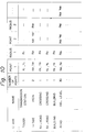
- Figure 10 shows an example of formats of the magnetic disturbance data.
- the large disturbance range is expressed by several points.
- the compensated driving direction of a vehicle is calculated with the normal ratio W0 when the vehicle drives in a normal area except the disturbance range and the ratio W changes to W x .
- W x is smaller than W0. Namely, the contribution ratio of the earth magnetism sensor is reduced in the disturbance range.
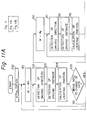
- Figures 11A and 11B show a flow-chart of the microcomputer operation for changing the weighted mean ratio W according to a locating position.
- An initialization is performed at step 200.
- a reference direction setting process and a starting position setting process are included in this initialization.
- the ratio W is set to W0 for the normal range.
- the microcomputer 31 detects the output of the flux gate sensor 1 and the optical fiber gyro 2 and calculates the compensated driving direction by the ratio W0.
- the microcomputer 31 detects the output of the wheel speed sensor 4 and calculates the driving distance.
- the microcomputer 31 calculates the locating position from the driving direction and the driving distance.
- step 205 it is determined whether or not the road map data in the microcomputer 31 is appropriate to the locating position, because the necessary road map data changes according to the locating position. If the change of the road map data is necessary, the microcomputer 31 reads the road map data and the magnetic disturbance data corresponding to the locating position at step 206. If it is not necessary, the control jumps to step 207.
- step 207 it is determined whether or not there are specific facilities in the neighborhood of the locating position. If there are no specific facilities, the control returns to step 202. If there are, the distances from the locating position to the specifications are calculated at step 208. Then, it is determined whether or not the locating position is within the disturbance range of the specific facilities. If the locating position is out of the disturbance range, the control returns to step 202. If the locating position is within the disturbance range, the control proceeds to step 210.
- the ratio W is set to W x .
- the operations from step 211 through 215 are the same as those of step 202 through 206 except the ratio W is different. Further, the operations from step 216 to 217 are the same as those of step 208 to 209. If the locating position is still within the disturbance range, the control returns to step 211. If the locating position is out of the disturbance range, the control returns to step 201.
- the compensated driving direction is determined only by the output of the rate gyro sensor within the disturbance range.
- the compensated driving direction is determined only by the output of the earth magnetism sensor out of the disturbance range.
- the ratio W changes between W0 and W x whether the locating position is within the disturbance range or not. Namely, the ratio W changes like a step function.
- the specific facility continuously disturbs the magnetic field. Therefore, if the ratio W changes according to the intensity of the disturbance, the compensated driving direction can improve.
- An embodiment in which the ratio W continuously changes according to the intensity of the disturbance is described in the following.
- the disturbance intensity changes according to the square of the distance from the specific facility. Therefore, when the magnetic disturbance data includes positions of the specific facility and intensities at centers, the disturbance intensity can be obtained by calculating the distance from the locating position to the specific facility.
- Figure 12 shows an example of a function of the ratio W changing according to the earth magnetism stability. The earth magnetism stability corresponds to the disturbance intensity.
- Figure 13 shows a flow-chart of the operation of the microcomputer in this embodiment. Since each of the operations is almost the same as that of Fig. 11, only different steps are explained.
- step 304 distances to specific facilities in the neighborhood of the locating position are calculated.
- step 305 each disturbance intensity of the specific facility in the neighborhood is calculated, and a total disturbing intensity is calculated by adding all disturbance intensities. And then, the ratio W is determined according to the function shown in Fig. 12.
- the magnetic disturbance data is expressed by specific facilities.
- the magnetic disturbance data can be expressed by another format. For example, all positions on the map are divided into several zones each of which respectively has the disturbance intensity of the same degree. And, the ratio W is determined according to the zone which the locating position belongs to. This magnetic disturbance data includes disturbances due to topological factors.
- the compensated driving direction is calculated by the weighted mean method.
- this method for changing the calculated process of the compensated driving direction according to the magnetic disturbance intensity at the locating position can be applied to other methods for calculating the compensated driving direction.
Landscapes
- Engineering & Computer Science (AREA)
- Radar, Positioning & Navigation (AREA)
- Remote Sensing (AREA)
- Automation & Control Theory (AREA)
- Physics & Mathematics (AREA)
- General Physics & Mathematics (AREA)
- Navigation (AREA)
- Gyroscopes (AREA)
Applications Claiming Priority (4)
| Application Number | Priority Date | Filing Date | Title |
|---|---|---|---|
| JP29899490A JPH04172214A (ja) | 1990-11-06 | 1990-11-06 | 方位センサ |
| JP298994/90 | 1990-11-06 | ||
| JP298993/90 | 1990-11-06 | ||
| JP2298993A JP2723352B2 (ja) | 1990-11-06 | 1990-11-06 | 車載用ナビゲーションシステム |
Publications (3)
| Publication Number | Publication Date |
|---|---|
| EP0485132A2 true EP0485132A2 (fr) | 1992-05-13 |
| EP0485132A3 EP0485132A3 (en) | 1992-07-29 |
| EP0485132B1 EP0485132B1 (fr) | 1996-03-06 |
Family
ID=26561744
Family Applications (1)
| Application Number | Title | Priority Date | Filing Date |
|---|---|---|---|
| EP91310150A Expired - Lifetime EP0485132B1 (fr) | 1990-11-06 | 1991-11-04 | Capteur de direction avec un capteur du magnétisme terrestre et un capteur gyroscopique du vitesse de rotation et système de navigation qui contient ce capteur de direction |
Country Status (3)
| Country | Link |
|---|---|
| US (1) | US5297050A (fr) |
| EP (1) | EP0485132B1 (fr) |
| DE (1) | DE69117661T2 (fr) |
Cited By (8)
| Publication number | Priority date | Publication date | Assignee | Title |
|---|---|---|---|---|
| GB2270758A (en) * | 1992-09-15 | 1994-03-23 | Platon A & I Limited | Apparatus for determining a parameter of a fluid |
| GB2314419A (en) * | 1996-06-22 | 1997-12-24 | Bosch Gmbh Robert | Determining rotational rate |
| WO1998049580A3 (fr) * | 1997-04-26 | 1999-02-04 | Bosch Gmbh Robert | Procede de determination de position servant a la navigation d'un vehicule a moteur dans la circulation routiere |
| WO2003069279A3 (fr) * | 2002-01-23 | 2004-02-26 | Triad Sensors Inc | Systeme et procede de navigation gyroscopique |
| EP0678228B1 (fr) * | 1993-01-05 | 2004-07-07 | Horizon Navigation, Inc. | Procede et dispositif de correction de la position destine a un systeme de navigation de vehicule |
| GB2460158A (en) * | 2008-05-20 | 2009-11-25 | Airmar Techn Corp | Dynamic motion control |
| EP2602590A1 (fr) * | 2011-12-07 | 2013-06-12 | Samsung Electronics Co., Ltd | Dispositif de terminal mobile pour système de positionnement basé sur une carte de champ magnétique et procédé associé |
| CN110081881A (zh) * | 2019-04-19 | 2019-08-02 | 成都飞机工业(集团)有限责任公司 | 一种基于无人机多传感器信息融合技术的着舰引导方法 |
Families Citing this family (44)
| Publication number | Priority date | Publication date | Assignee | Title |
|---|---|---|---|---|
| JP2664800B2 (ja) * | 1990-09-19 | 1997-10-22 | 三菱電機株式会社 | 車両用ナビゲーション装置 |
| US5758313A (en) * | 1992-10-16 | 1998-05-26 | Mobile Information Systems, Inc. | Method and apparatus for tracking vehicle location |
| US5428546A (en) * | 1992-10-16 | 1995-06-27 | Mobile Information Systems | Method and apparatus for tracking vehicle location |
| US5381095A (en) * | 1993-06-21 | 1995-01-10 | Rockwell International Corporation | Method of estimating location and orientation of magnetic dipoles using extended Kalman filtering and Schweppe likelihood ratio detection |
| US5515283A (en) * | 1994-06-20 | 1996-05-07 | Zexel Corporation | Method for identifying highway access ramps for route calculation in a vehicle navigation system |
| US5712788A (en) * | 1995-02-09 | 1998-01-27 | Zexel Corporation | Incremental route calculation |
| US5938720A (en) * | 1995-02-09 | 1999-08-17 | Visteon Technologies, Llc | Route generation in a vehicle navigation system |
| US5922040A (en) * | 1995-05-17 | 1999-07-13 | Mobile Information System, Inc. | Method and apparatus for fleet management |
| US5904727A (en) * | 1995-05-17 | 1999-05-18 | Mobile Information Systems, Inc. | Graphical fleet management methods |
| US5731978A (en) * | 1995-06-07 | 1998-03-24 | Zexel Corporation | Method and apparatus for enhancing vehicle navigation through recognition of geographical region types |
| US5902351A (en) * | 1995-08-24 | 1999-05-11 | The Penn State Research Foundation | Apparatus and method for tracking a vehicle |
| US5898390A (en) * | 1995-09-14 | 1999-04-27 | Zexel Corporation | Method and apparatus for calibration of a distance sensor in a vehicle navigation system |
| US5987375A (en) * | 1996-02-14 | 1999-11-16 | Visteon Technologies, Llc | Method and apparatus for selecting a destination in a vehicle navigation system |
| US5819200A (en) * | 1996-02-14 | 1998-10-06 | Zexel Corporation | Method and apparatus for selecting a destination in a vehicle navigation system |
| US6029110A (en) * | 1996-09-30 | 2000-02-22 | Visteon Technologies, Llc | Method and apparatus for providing passenger access to a vehicle navigation system |
| US5904728A (en) * | 1996-10-11 | 1999-05-18 | Visteon Technologies, Llc | Voice guidance timing in a vehicle navigation system |
| US5902350A (en) * | 1996-10-30 | 1999-05-11 | Visteon Technologies, Llc | Generating a maneuver at the intersection through a turn lane |
| US6253154B1 (en) | 1996-11-22 | 2001-06-26 | Visteon Technologies, Llc | Method and apparatus for navigating with correction of angular speed using azimuth detection sensor |
| US5910177A (en) * | 1996-12-09 | 1999-06-08 | Visteon Technologies, Llc | Navigating close proximity routes with a vehicle navigation system |
| US5928307A (en) * | 1997-01-15 | 1999-07-27 | Visteon Technologies, Llc | Method and apparatus for determining an alternate route in a vehicle navigation system |
| US6889139B2 (en) * | 1997-03-07 | 2005-05-03 | Sidewinder Holdings Ltd. | System and method for mobile data processing and transmission |
| US6212472B1 (en) | 1997-09-04 | 2001-04-03 | Visteon Technologies, Llc | Method and apparatus for displaying current vehicle position |
| US6144919A (en) | 1998-03-27 | 2000-11-07 | Visteon Technologies, Llc | Method and apparatus for using non-digitized cities for route calculation |
| US6097316A (en) * | 1998-04-20 | 2000-08-01 | Visteon Technologies, Llc | Communication protocol for a vehicle navigation system |
| US6298305B1 (en) | 1998-07-15 | 2001-10-02 | Visteon Technologies, Llc | Methods and apparatus for providing voice guidance in a vehicle navigation system |
| US6088649A (en) * | 1998-08-05 | 2000-07-11 | Visteon Technologies, Llc | Methods and apparatus for selecting a destination in a vehicle navigation system |
| US6459990B1 (en) * | 1999-09-23 | 2002-10-01 | American Gnc Corporation | Self-contained positioning method and system thereof for water and land vehicles |
| US6360165B1 (en) | 1999-10-21 | 2002-03-19 | Visteon Technologies, Llc | Method and apparatus for improving dead reckoning distance calculation in vehicle navigation system |
| US6282496B1 (en) | 1999-10-29 | 2001-08-28 | Visteon Technologies, Llc | Method and apparatus for inertial guidance for an automobile navigation system |
| US6456935B1 (en) | 2000-03-28 | 2002-09-24 | Horizon Navigation, Inc. | Voice guidance intonation in a vehicle navigation system |
| US6735516B1 (en) | 2000-09-06 | 2004-05-11 | Horizon Navigation, Inc. | Methods and apparatus for telephoning a destination in vehicle navigation |
| US6813582B2 (en) * | 2002-07-31 | 2004-11-02 | Point Research Corporation | Navigation device for personnel on foot |
| US6842991B2 (en) * | 2002-07-31 | 2005-01-18 | Robert W. Levi | Gyro aided magnetic compass |
| US7103471B2 (en) | 2002-09-20 | 2006-09-05 | Honeywell International Inc. | Multi-mode navigation device and method |
| JP4710740B2 (ja) * | 2006-07-04 | 2011-06-29 | 株式会社デンソー | 位置情報利用装置 |
| RU2597658C2 (ru) * | 2010-11-08 | 2016-09-20 | ЭлпайнРиплей, Инк. | Устройство и способ калибровки гиродатчиков |
| WO2012135960A1 (fr) * | 2011-04-06 | 2012-10-11 | Uti Limited Partnership | Système et procédé pour l'estimation d'erreurs de gyroscope |
| JP5927776B2 (ja) * | 2011-05-20 | 2016-06-01 | 株式会社ソニー・インタラクティブエンタテインメント | 携帯機器 |
| US8996298B2 (en) * | 2011-06-13 | 2015-03-31 | Panasonic Intellectual Property Corporation Of America | Noise pattern acquisition device and position detection apparatus provided therewith |
| US9060682B2 (en) | 2012-10-25 | 2015-06-23 | Alpinereplay, Inc. | Distributed systems and methods to measure and process sport motions |
| DE102014211175A1 (de) * | 2014-06-11 | 2015-12-17 | Continental Teves Ag & Co. Ohg | Verfahren und System zur Initialisierung eines Sensorfusionssystems |
| US10451438B2 (en) | 2015-02-05 | 2019-10-22 | Alpinereplay, Inc. | Systems and methods for in-motion gyroscope calibration |
| US10392982B2 (en) * | 2016-02-02 | 2019-08-27 | Denso International America, Inc. | Emissions control substrate |
| US20250044110A1 (en) * | 2023-08-01 | 2025-02-06 | GM Global Technology Operations LLC | Navigation system for highlighting a target location of a destination by infrared light |
Family Cites Families (23)
| Publication number | Priority date | Publication date | Assignee | Title |
|---|---|---|---|---|
| JPS5784310A (en) * | 1980-11-13 | 1982-05-26 | Alps Electric Co Ltd | Direction sensing means |
| JPS57201808A (en) * | 1981-06-08 | 1982-12-10 | Nippon Denso Co Ltd | Navigator to be mounted on car |
| JPS5833284A (ja) * | 1981-08-21 | 1983-02-26 | 本田技研工業株式会社 | 移動体の現在位置表示装置 |
| JPS5833283A (ja) * | 1981-08-21 | 1983-02-26 | 本田技研工業株式会社 | 移動体の現在位置表示装置 |
| JPS59218913A (ja) * | 1983-05-27 | 1984-12-10 | Honda Motor Co Ltd | 移動方向検出方式 |
| BR8504010A (pt) * | 1984-08-21 | 1986-06-10 | Mobil Oil Corp | Processo para preparacao de zeolito cristalino poroso sintetico e processo para efetuar conversao catalitica de carga organica |
| JPH0643899B2 (ja) * | 1985-03-20 | 1994-06-08 | 日産自動車株式会社 | 車両用経路誘導装置 |
| JPS62163721A (ja) * | 1986-01-13 | 1987-07-20 | Shintou Dasutokorekutaa Kk | ガス清浄装置 |
| KR900008856B1 (ko) * | 1986-06-12 | 1990-12-11 | 미쓰비시 뎅끼 가부시끼가이샤 | 차재용 주행정보 표시장치 |
| JPS6311810A (ja) * | 1986-07-01 | 1988-01-19 | Pioneer Electronic Corp | 地磁気センサの出力デ−タの処理方法 |
| JPS63150616A (ja) * | 1986-12-15 | 1988-06-23 | Honda Motor Co Ltd | 走行経路表示装置 |
| US4879658A (en) * | 1987-02-10 | 1989-11-07 | Yazaki Corporation | Navigation system using angular rate sensor |
| JPS63295913A (ja) * | 1987-05-28 | 1988-12-02 | Matsushita Electric Ind Co Ltd | 車両位置検出装置 |
| JPS6435315A (en) * | 1987-07-31 | 1989-02-06 | Mazda Motor | On-vehicle navigation system |
| JPS6435314A (en) * | 1987-07-31 | 1989-02-06 | Mazda Motor | On-vehicle navigation system |
| JPS6435318A (en) * | 1987-07-31 | 1989-02-06 | Mazda Motor | On-vehicle navigation system |
| JPS6435316A (en) * | 1987-07-31 | 1989-02-06 | Mazda Motor | On-vehicle navigation system |
| JPS6435317A (en) * | 1987-07-31 | 1989-02-06 | Mazda Motor | On-vehicle navigation system |
| JPH01219610A (ja) * | 1988-02-29 | 1989-09-01 | Nissan Motor Co Ltd | 車両用走行方位検出装置 |
| US5109344A (en) * | 1988-04-28 | 1992-04-28 | Mazda Motor Corporation | Vehicle navigation apparatus employing node selection, comparison and elimination techniques |
| JPH07119617B2 (ja) * | 1988-07-05 | 1995-12-20 | マツダ株式会社 | 車両用ナビゲーシヨン装置 |
| JPH07119612B2 (ja) * | 1989-01-13 | 1995-12-20 | 日産自動車株式会社 | 車両用走行方位検出装置 |
| JPH03279809A (ja) * | 1990-03-28 | 1991-12-11 | Sumitomo Electric Ind Ltd | 方位検出装置 |
-
1991
- 1991-11-04 EP EP91310150A patent/EP0485132B1/fr not_active Expired - Lifetime
- 1991-11-04 DE DE69117661T patent/DE69117661T2/de not_active Expired - Lifetime
- 1991-11-06 US US07/788,456 patent/US5297050A/en not_active Expired - Lifetime
Cited By (15)
| Publication number | Priority date | Publication date | Assignee | Title |
|---|---|---|---|---|
| GB2270758A (en) * | 1992-09-15 | 1994-03-23 | Platon A & I Limited | Apparatus for determining a parameter of a fluid |
| EP0678228B1 (fr) * | 1993-01-05 | 2004-07-07 | Horizon Navigation, Inc. | Procede et dispositif de correction de la position destine a un systeme de navigation de vehicule |
| GB2314419A (en) * | 1996-06-22 | 1997-12-24 | Bosch Gmbh Robert | Determining rotational rate |
| GB2314419B (en) * | 1996-06-22 | 1998-09-02 | Bosch Gmbh Robert | Device for determining yaw rate |
| US5890099A (en) * | 1996-06-22 | 1999-03-30 | Robert Bosch Gmbh | Apparatus for measuring a turning rate, particularly of a motor vehicle |
| WO1998049580A3 (fr) * | 1997-04-26 | 1999-02-04 | Bosch Gmbh Robert | Procede de determination de position servant a la navigation d'un vehicule a moteur dans la circulation routiere |
| WO2003069279A3 (fr) * | 2002-01-23 | 2004-02-26 | Triad Sensors Inc | Systeme et procede de navigation gyroscopique |
| US6853315B2 (en) | 2002-01-23 | 2005-02-08 | Triad Sensors, Inc. | Piezoelectric rate sensor system and method |
| GB2460158A (en) * | 2008-05-20 | 2009-11-25 | Airmar Techn Corp | Dynamic motion control |
| GB2460158B (en) * | 2008-05-20 | 2012-06-20 | Airmar Techn Corp | Dynamic motion control |
| US8326561B2 (en) | 2008-05-20 | 2012-12-04 | Airmar Technology Corporation | Dynamic motion control |
| EP2602590A1 (fr) * | 2011-12-07 | 2013-06-12 | Samsung Electronics Co., Ltd | Dispositif de terminal mobile pour système de positionnement basé sur une carte de champ magnétique et procédé associé |
| US9167440B2 (en) | 2011-12-07 | 2015-10-20 | Samsung Electronics Co., Ltd. | Mobile terminal device for positioning system based on magnetic field map and method thereof |
| US9453932B2 (en) | 2011-12-07 | 2016-09-27 | Samsung Electronics Co., Ltd. | Mobile terminal device for positioning system based on magnetic field map and method thereof |
| CN110081881A (zh) * | 2019-04-19 | 2019-08-02 | 成都飞机工业(集团)有限责任公司 | 一种基于无人机多传感器信息融合技术的着舰引导方法 |
Also Published As
| Publication number | Publication date |
|---|---|
| EP0485132B1 (fr) | 1996-03-06 |
| US5297050A (en) | 1994-03-22 |
| DE69117661T2 (de) | 1996-07-18 |
| DE69117661D1 (de) | 1996-04-11 |
| EP0485132A3 (en) | 1992-07-29 |
Similar Documents
| Publication | Publication Date | Title |
|---|---|---|
| US5297050A (en) | Direction sensor having an earth magnetism sensor and a rate gyro sensor and navigation system having this direction sensor | |
| EP0763713B1 (fr) | Méthode et appareil pour l'étalonnage d'un capteur de distance dans un système de navigation véhiculaire | |
| US6014610A (en) | Navigation system and method | |
| CA2081185C (fr) | Systeme de navigation pour mobiles | |
| US4890233A (en) | Vehicle bearing detection and data processing methods applicable to vehicle navigation system | |
| US6226591B1 (en) | Vehicle present position detection apparatus, vehicle present position display apparatus, navigation system and recording medium | |
| EP0678228B1 (fr) | Procede et dispositif de correction de la position destine a un systeme de navigation de vehicule | |
| US5761094A (en) | Vehicle compass system | |
| EP0314806B1 (fr) | Systeme detecteur de position | |
| US5345382A (en) | Calibration method for a relative heading sensor | |
| CA1268240A (fr) | Generateur de signaux de cap pour vehicule terrestre | |
| EP0451988B1 (fr) | Appareil pour la détection de cap | |
| JPH0555806B2 (fr) | ||
| US6766247B2 (en) | Position determination method and navigation device | |
| JPS60229799A (ja) | 車載用ナビゲ−タ | |
| EP0496508A1 (fr) | Méthode pour la détection de cap | |
| US5367898A (en) | Method of calculating scale factor of gyro | |
| US5151872A (en) | Method and apparatus for correcting the output of an onboard vehicle terrestrial magnetism sensor | |
| JP3112405B2 (ja) | 車両位置検出装置 | |
| JPH0833300B2 (ja) | 電子コンパスを備えた車両用のナビゲーシヨン方法 | |
| EP0451839B1 (fr) | Appareil pour la détermination d'une direction | |
| JPH0833302B2 (ja) | 位置検出装置 | |
| AU723107B2 (en) | Method to determine correction parameters | |
| JPH0462419A (ja) | 方位検出装置 | |
| JPH04172216A (ja) | 車載用ナビゲーションシステム |
Legal Events
| Date | Code | Title | Description |
|---|---|---|---|
| PUAI | Public reference made under article 153(3) epc to a published international application that has entered the european phase |
Free format text: ORIGINAL CODE: 0009012 |
|
| 17P | Request for examination filed |
Effective date: 19911122 |
|
| AK | Designated contracting states |
Kind code of ref document: A2 Designated state(s): DE FR GB |
|
| PUAL | Search report despatched |
Free format text: ORIGINAL CODE: 0009013 |
|
| AK | Designated contracting states |
Kind code of ref document: A3 Designated state(s): DE FR GB |
|
| 17Q | First examination report despatched |
Effective date: 19940217 |
|
| GRAA | (expected) grant |
Free format text: ORIGINAL CODE: 0009210 |
|
| AK | Designated contracting states |
Kind code of ref document: B1 Designated state(s): DE FR GB |
|
| REF | Corresponds to: |
Ref document number: 69117661 Country of ref document: DE Date of ref document: 19960411 |
|
| ET | Fr: translation filed | ||
| PLBE | No opposition filed within time limit |
Free format text: ORIGINAL CODE: 0009261 |
|
| STAA | Information on the status of an ep patent application or granted ep patent |
Free format text: STATUS: NO OPPOSITION FILED WITHIN TIME LIMIT |
|
| 26N | No opposition filed | ||
| REG | Reference to a national code |
Ref country code: GB Ref legal event code: IF02 |
|
| PGFP | Annual fee paid to national office [announced via postgrant information from national office to epo] |
Ref country code: FR Payment date: 20101123 Year of fee payment: 20 |
|
| PGFP | Annual fee paid to national office [announced via postgrant information from national office to epo] |
Ref country code: DE Payment date: 20101027 Year of fee payment: 20 |
|
| PGFP | Annual fee paid to national office [announced via postgrant information from national office to epo] |
Ref country code: GB Payment date: 20101103 Year of fee payment: 20 |
|
| REG | Reference to a national code |
Ref country code: DE Ref legal event code: R071 Ref document number: 69117661 Country of ref document: DE |
|
| REG | Reference to a national code |
Ref country code: DE Ref legal event code: R071 Ref document number: 69117661 Country of ref document: DE |
|
| REG | Reference to a national code |
Ref country code: GB Ref legal event code: PE20 Expiry date: 20111103 |
|
| PG25 | Lapsed in a contracting state [announced via postgrant information from national office to epo] |
Ref country code: GB Free format text: LAPSE BECAUSE OF EXPIRATION OF PROTECTION Effective date: 20111103 |
|
| PG25 | Lapsed in a contracting state [announced via postgrant information from national office to epo] |
Ref country code: DE Free format text: LAPSE BECAUSE OF EXPIRATION OF PROTECTION Effective date: 20111105 |