EP0485324B1 - Procédé et dispositif pour changer des bobines de mèche dans un continu à filer à anneaux - Google Patents
Procédé et dispositif pour changer des bobines de mèche dans un continu à filer à anneaux Download PDFInfo
- Publication number
- EP0485324B1 EP0485324B1 EP91810741A EP91810741A EP0485324B1 EP 0485324 B1 EP0485324 B1 EP 0485324B1 EP 91810741 A EP91810741 A EP 91810741A EP 91810741 A EP91810741 A EP 91810741A EP 0485324 B1 EP0485324 B1 EP 0485324B1
- Authority
- EP
- European Patent Office
- Prior art keywords
- bobbin
- roving
- roving bobbins
- pair
- bobbins
- Prior art date
- Legal status (The legal status is an assumption and is not a legal conclusion. Google has not performed a legal analysis and makes no representation as to the accuracy of the status listed.)
- Expired - Lifetime
Links
- 238000007378 ring spinning Methods 0.000 title claims description 37
- 238000000034 method Methods 0.000 title claims description 33
- 238000009987 spinning Methods 0.000 claims description 136
- 230000000153 supplemental effect Effects 0.000 claims description 96
- 238000010977 unit operation Methods 0.000 claims description 46
- 230000033001 locomotion Effects 0.000 claims description 40
- 230000007246 mechanism Effects 0.000 claims description 21
- 238000006073 displacement reaction Methods 0.000 claims description 17
- 238000010276 construction Methods 0.000 claims description 3
- 230000009471 action Effects 0.000 description 9
- 230000002441 reversible effect Effects 0.000 description 7
- 239000000725 suspension Substances 0.000 description 7
- 238000000926 separation method Methods 0.000 description 5
- 230000004048 modification Effects 0.000 description 4
- 238000012986 modification Methods 0.000 description 4
- 230000008569 process Effects 0.000 description 4
- 230000008901 benefit Effects 0.000 description 3
- 239000007787 solid Substances 0.000 description 2
- 230000008859 change Effects 0.000 description 1
- 239000000470 constituent Substances 0.000 description 1
- 230000001419 dependent effect Effects 0.000 description 1
- 230000012447 hatching Effects 0.000 description 1
- 230000006872 improvement Effects 0.000 description 1
- 230000002093 peripheral effect Effects 0.000 description 1
- 230000001105 regulatory effect Effects 0.000 description 1
- 238000011144 upstream manufacturing Methods 0.000 description 1
- 238000004804 winding Methods 0.000 description 1
Images
















Classifications
-
- D—TEXTILES; PAPER
- D01—NATURAL OR MAN-MADE THREADS OR FIBRES; SPINNING
- D01H—SPINNING OR TWISTING
- D01H9/00—Arrangements for replacing or removing bobbins, cores, receptacles, or completed packages at paying-out or take-up stations ; Combination of spinning-winding machine
- D01H9/005—Arrangements for replacing or removing bobbins, cores, receptacles, or completed packages at paying-out or take-up stations ; Combination of spinning-winding machine for removing empty packages or cans and replacing by completed (full) packages or cans at paying-out stations; also combined with piecing of the roving
Definitions
- the present invention relates to a method and apparatus for exchanging roving bobbins in a ring spinning frame, more particularly relates to an improved method and apparatus for exchanging roving bobbins in a ring spinning frame during a continuous spinning operation thereof.
- Japanese Unexamined Patent Publication No. 2-127368 also discloses an apparatus for carrying out to a ring roving bobbin exchange method to be applied to a ring spinning frame, wherein a tapered arrangement of roving bobbins is applied as described hereafter. Namely, at the start of the spinning operation, two types of roving bobbins, i. e., an almost half exhausted roving bobbin, and a full packaged roving bobbin, are alternately supported by a front and back row of bobbin hangers in the ring spinning frame.
- a pair of almost exhausted roving bobbins one of which is a roving bobbin supported by a bobbin hanger of the front row and the other is a roving bobbin supported by a bobbin hanger of the back row and facing the bobbin hanger of the front row, are exchanged with a pair of full packaged roving bobbins supported by two adjacent bobbin hangers of a bobbin carriage prepared on a supplemental bobbin rail arranged along and in front of the ring spinning frame.
- the automatic roving bobbin exchange operation is carried out successively along the ring spinning frame until the roving bobbin exchange operation of all of the almost exhausted roving bobbins of one side of the ring spinning frame is completed. Therefore, in this automatic apparatus for carrying out the roving bobbin exchange method, it is essential to arrange a device for transferring almost exhausted roving bobbins and having a pair of pegs and a device for transferring full package roving bobbins and also having a pair of pegs in parallel on a body of the roving bobbin exchange apparatus, wherein the pitch between the row of the pegs of the transfer device for the almost exhausted roving bobbins and the row of the pegs of the transfer device for the full packaged roving bobbins is equal to the pitch of bobbin hangers of the front and back rows in the ring spinning frame, and accordingly, it is necessary to provide a space in which the above-mentioned two devices may be arranged in the lengthwise direction of the
- Japanese Unexamined Patent Publication no. 2-127368 also discloses an automatic roving bobbin exchange apparatus in which the above-mentioned invention is modified by combining a roving piecing device therewith.
- the time needed for completing the roving bobbin exchange operation can be remarkably reduced in comparison with that of the second mentioned prior art.
- the application of the first mentioned prior art is limited to only a ring spinning frame provided with an apparatus for exchanging a roving bobbin and carrying out such an exchange between the bobbin hanger of the front row and a roving bobbin hanger of the back row facing the above-mentioned bobbin hanger of the front row.
- the second mentioned prior art has an advantage of being able to be applied to a ring spinning frame without the need for the above-mentioned roving bobbin exchange apparatus, which is essential to the first mentioned prior art, but the time needed for completing the roving bobbin exchange operation is very long, in comparison with that of the first mentioned prior art, because of the transfer of two almost exhausted roving bobbins and of two full packaged roving bobbins. Therefore, for the above-mentioned reasons, the roving bobbin exchange operations based upon the first and second mentioned prior arts are not satisfactory.
- an improvement such that a plurality of sets of a unit combination of the almost empty roving bobbin exchange device and the full package roving bobbin exchange device are mounted on the automatic roving bobbin exchange apparatus, to thereby simultaneously carry out the roving bobbin exchange operation for a plurality of sets of almost exhausted roving bobbins could be adopted.
- each set of almost exhausted roving bobbins would consist of an almost exhausted roving bobbin supported by a bobbin hanger of the front row and an almost exhausted roving bobbin supported by a bobbin hanger of the back row facing the bobbin hanger of the front row, with the respective full packaged roving bobbins supported by the corresponding bobbin hangers of the bobbin carriage supported by the supplemental rail.
- Such a modification of the second mentioned invention is not practical, however because of the resulting mechanical complications of the constituent machine elements and interferences occurring due to the motions of these machine elements.
- the object of the present invention is to provide a method and apparatus for simultaneously exchanging a plurality of pairs of almost exhausted roving bobbins, wherein each pair of almost exhausted roving bobbins consists of an almost exhausted roving bobbin of the front row and an almost exhausted roving bobbin of the back row facing the almost exhausted roving bobbin of the front row, with full packaged roving bobbins supported by the corresponding bobbin hangers of the bobbin carriage carried to a transfer position on the supplemental rail.
- Another object of the present invention is to provide an improved method and an apparatus for carrying out the roving bobbin exchange operation in a very stable condition, which is applied to a ring spinning frame having creel row arranged at a comparatively lower position than in the conventional ring spinning frame.
- the roving bobbin exchange operation is carried out by a method as defined in claim 1 and an apparatus as defined in claim 9, with preferred embodiments defined in dependent claims 2-8 and 10-17.
- a pair of full packaged roving bobbins FB which corresponds to a pair of almost exhausted roving bobbins SB supported by the corresponding pair of a front and back bobbin hanger of the creel portion of the spinning frame, are transferred to a roving bobbin exchanging apparatus, then one of the above-mentioned pair of full packaged roving bobbins FB is displaced to a position in front or back of the first mentioned full packaged roving bobbin FB with respect to the apparatus, then the above-mentioned almost exhausted roving bobbins SB are taken from the bobbin hangers of the creel portion of the spinning frame and displaced to positions adjacent to the above-mentioned row of full packaged roving bobbins FB on the apparatus, thereafter the full packaged roving bobbins FB which have been changed in their arrangement are mounted on the above-mentione
- the above-mentioned unit operation is simultaneously applied to a plurality of successive pairs of bobbin hangers holding almost exhausted roving bobbins while the apparatus is stopped at its unit working position. After completion of the operation, the apparatus is displaced by one pitch along the lengthwise direction of the ring spinning frame. Such a stepwise operation is repeated until all the almost exhausted roving bobbins supported by the bobbin hangers of a creel portion of one aide of the spinning frame are exchanged.
- a supplemental step of temporarily reserving a roving bobbin in the apparatus can be applied.
- a peg unit comprising a pair of sub-peg units provided with two pegs for supporting roving bobbins and having a main function of changing the arrangement direction of these two pegs between two directions; a direction along the lengthwise direction of the spinning frame and a direction perpendicular to the above-mentioned direction.
- Each of these sub-peg units is provided with a function to displace the roving bobbins between a creel position below the corresponding pair of bobbin hangers to which the roving bobbin exchange operation is required and a standby position on the apparatus.
- supplementary mechanisms such as a mechanism to displace the sub-peg units upward and downward, a roving piecing mechanism, and a device for temporarily reserving a roving bobbin on the apparatus, may be adopted to improve the function of the roving bobbin exchange apparatus according to the present invention.
- the direction transverse to the lengthwise direction of a ring spinning frame is simply indicated as the transverse direction.
- the outside position and inside position with respect to the center row along the lengthwide direction of the spinning frame are hereinafter indicated as the front position and back position, respectively.
- a plurallity of pillars 3 are vertically arranged along the lengthwise direction of the spinning frame 1 at a predetermined pitch therebetween, and a horizontal bracket 4b is rigidly supported by each creel pillar 3.
- a pair of supporting rails 5 and 6, which extend in parallel along the lengthwise direction of the spinning frame 1 are rigidly supported by a corresponding one side portion of the horizontal brackets 4b.
- the front supporting rail 5 and the back supporting rail 6 are rigidly supported by the horizontal brackets 4b at each side of the spinning frame 1.
- the front supporting rail 5 and the back supporting rail 6 are provided with a plurality of bobbin hangers (7a and 7b).
- the number of bobbin hangers 7 is one-fourth of the total number of spindles of the spinning frame 1.
- the pitch A2 between two adjacent bobbin hangers of the supporting rail 5 and that of the supporting rail 6 is double the pitch A1 between two adjacent trumpets 14 which are utilized to introduce a roving into the corresponding draft parts 15 of the spinning frame.
- Figs. 24 and 25 The relative positions of the roving bobbins (full packaged roving bobbins are indicated by FB and almost exhausted roving bobbins are indicated by SB) supported by the bobbin hangers 7 (not shown) in the ring spinning frame 1 are clearly shown in Figs. 24 and 25.
- Fig. 25 the arrangement of two roving guides 9 is shown in relation to the arrangement of two full packaged roving bobbins, one of which is a full packaged roving bobbin 10A supported by a front bobbin hanger 7A and the other of which is a full packaged roving bobbin 10B supported by a back bobbin hanger 7B facing the front bobbin hanger 7A.
- the roving guides 9 are arranged at intermediate positions between the rows of the front bobbin hangers 7A and the back bobbin hangers 7B along the lengthwise direction of the ring spinning frame 1. As shown in Fig. 25, each roving guide 9 is formed in the shape of the letter "C" having an opening 8 facing the front side of the spinning frame 1. The pitch between these two roving guides 9 is identical to the above-mentioned pitch A2.
- Each roving guide 9 is suspended from the corresponding supporting bracket 4b at respective positions between two adjacent supporting brackets 4b, by way of a spring element 9A, so that the roving guide 9 will not disturb the operation of the roving bobbin exchange operation because the roving guide 9 can move outward from the standby position thereof with respect to the above-mentioned full packaged roving bobbin FB, when the full packaged roving bobbin 10B is displaced toward the inside of the spinning frame 1, and the roving guides 9 are returned to their respective standby positions after the full packaged roving bobbin 10B has passed through the space therebetween. As shown in Fig.
- each row of the bobbin hangers 7 full packaged roving bobbins FB and almost half exhausted roving bobbins MB are arranged alternately at the start of the spinning operation, and the size of each of the two roving bobbins supported by each pair of two bobbin hangers 7, one of which is a front bobbin hanger 7A and the other of which is a back bobbin hanger 7B facing the front bobbin hanger 7A, is identical.
- Each pair of bobbin hangers 7 is hereinafter referred to as a pair of bobbin hangers P1.
- Another supporting bracket 4a provided with horizontal portions extended from the pillar 3 toward both front sides of the spinning frame 1, is rigidly mounted on the top end portion of each pillar 3, and a supplemental rail 11 having a rectangular cross-section is rigidly supported by the outer end portion of the supporting brackets 4a at each side of the spinning frame 1, such that the supplemental rail 11 is arranged along the lengthwise direction of the spinning frame at both sides of the spinning frame 1.
- the supplemental rail 11 is provided with a downward facing opening and is set at a position slightly higher than the level of the outer end of the supporting bracket 4b, in such a manner that the rail 11 is able to temporarily support a bobbin carriage 13 provided with a number of of bobbin hangers 12 which is identical to or more than the number of bobbin hangers 7A in the front row thereof, a pitch A2 between each two adjacent bobbin hangers 12, at each side of the spinning frame 1.
- the bobbin carriage 13 supporting the full packaged roving bobbins FB on the bobbin hangers 12 is displaced toward the supplemental rail 11, and there awaits the roving exchange operation at a standby position at which the full packaged roving bobbins FB face the group of roving bobbins for which the roving bobbin exchange operation is to be carried out.
- the position of the supplemental rail 11 is such that, when the bobbin carriage 13 is carried to the standby position, the bottom ends of the roving bobbins are positioned below the upper ends of the roving bobbins moved from the bobbin hangers of the ring spinning frame onto the roving bobbin exchange apparatus.
- the apparatus 20 has a function of carrying out the roving piecing operation and a function of temporarily holding a roving bobbin to thereby prevent any interference between roving bobbins supported by the bobbin hangers 12 of the bobbin carriage 13 while at the standby position of the supplemental rail 11, and a roving bobbin moved by the apparatus 20.
- the apparatus 20 has a function of carrying out the roving piecing operation and a function of temporarily holding a roving bobbin to thereby prevent any interference between roving bobbins supported by the bobbin hangers 12 of the bobbin carriage 13 while at the standby position of the supplemental rail 11, and a roving bobbin moved by the apparatus 20.
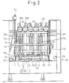
- the apparatus 20 is provided with a pair of wheels 22 rotatably disposed at respective positions below the main body 21 and a pair of guide rollers 23 rotatably disposed at respective positions of the main body 21, in such a manner that the guide rollers 23 are able to move along a horizontal guide rail la disposes lengthwise of the spinning frame 1.
- the apparatus 20 is displaced by engaging a scroll cam (not shown) driven by a drive motor (not shown) mounted on the apparatus 20 and guide pins (not shown) projected from the guide rail 1a, and the displacement of the apparatus 20 is regulated so that it is stopped at the respective working positions thereof.
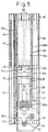
- the main body 21 of the apparatus 20 is provided with a plurality of peg units (in this embodiment, six peg units are utilized) 30A, 30B which are utilized for simultaneously exchanging almost exhausted roving bobbins SB supported by the respective bobbin hangers 7A, 7B and forming pairs P1 (shown in Fig. 24) with the full packaged roving bobbins FB supported by the corresponding bobbin hangers 12 of the bobbin carriage 13.
- the roving bobbin exchange operation is simultaneously applied to three pairs P1 of the bobbin hangers 7A, 7B of the spinning frame.
- the apparatus 20 is also provided with a device 70 for taking a free end of roving from the plurality of full packaged roving bobbins FB supported by the respective peg units 30A and 30B, by air suction; a piecing device 100 for joining the free end of the roving taken by the device 70 with a free end of a corresponding roving taken from the corresponding almost exhausted roving bobbin SB for which the roving bobbin exchange operation is carried out and supplying it to a draft part which corresponds to the almost exhausted driving bobbin; a device 130 for hanging the rovings from the full packaged roving bobbins FB onto the corresponding roving guides 9; a device 160 for temporarily holding the full packaged roving bobbins FB taken from the bobbin hangers 12 of the bobbin carriage 13 while maintaining the pitch A2 between each two adjacent full packaged roving bobbins FB at the corresponding standby positions S6 (see Fig.
- a bobbin reserve device 160 for temporarily reserving a full packaged bobbin at a pitch A2 at a standby position S6 (Fig. 26) away from the bobbin hanger 12 of the bobbin carriage 13a and away from directly under the supplemental rail 11; and means for driving the above-mentioned component devices.
- a plurality of bobbin holding members 30, each of them constituted by a first peg unit 30A utilized for handling a pair of almost exhausted roving bobbins SB and a second peg unit 30B utilized for handling a pair of full packaged roving bobbins FB, arranged with a pitch Al when they are maintained in their standby position on a main body 12 of the roving bobbin exchanging apparatus 20.
- a first peg unit 30A utilized for handling a pair of almost exhausted roving bobbins SB
- a second peg unit 30B utilized for handling a pair of full packaged roving bobbins FB
- each row of the bobbin hangers 7 full packaged roving bobbins FB and almost half exhausted roving bobbins MB are alternately arranged at the start of the spinning operation, and the size of each of the two roving bobbins supported by each pair of two bobbin hangers 7, one of which is a front bobbin hanger 7A, and the other of which is a back bobbin hanger 7B facing the above-mentioned front bobbin hanager 7A, is identical.
- Each pair of bobbin hangers 7 is hereinafter referred to as a pair of bobbin hangers P1.
- the front block 31c and the intermediate block 31d are connected by a pair of horizontal guide rods 35 extended perpendicularly to the lengthwise direction of the spinning frame 1, and a supporting body 36 is slidably mounted on the guide rods 35 and is able to move for a predetermined distance along the guide rods 35.
- the front block 31c is connected to the bottom surface of the back portion of the supporting body 36 by a cylinder 44.
- the front portion of the supporting body 36 is formed by an upwardly projected body 36a.
- a stationary gear 37 provided with an upright shaft 37a is rigidly mounted on the projected body, as shown in Fig. 4, and a bottom portion of a swing arm 38 is turnably mounted on the upright shaft 37a in such a manner that the swing arm 38 is able to swing about the upright shaft 37a.
- a swing motor 39 is mounted on the swing arm 38 and a gear 40 is arranged in such a manner that the gear 40 is driven by the motor 39 so that the swing motion of the swing arm 38 is actuated by meshing the gear 40 with the stationary gear 37.
- the back peg 41 which together with the front peg 32 forms a pair of pegs P1 is rotatably mounted on an upper surface of the front end portion of the swing arm 38 at the same level as that of the front peg 32, and the back peg 41 is rotated by a reversible motor 42 disposed on the upper surface of the swing arm 38 through a gear train as shown in Fig. 4.
- the rovings R2 taken from the full packaged roving bobbins FB mounted on the pegs 32, 41 are slackened, to create a suitable slackened condition, by rotating the pegs 32 and 41 for a predetermined number of rotations in the clockwise direction or the counter clockwise direction.
- the distance between the axial center of the upright shaft 37a and the axial center of the back peg 41, which corresponds to the turning radius of the displacing motion of the back peg 41 by the swing motion of the swing arm 38, plus the displacing distance of the supporting body 36 toward the direction perpendicular to the lengthwise direction of the spinning frame 1 satisfy the condition that, when the supporting body 36 is positioned at a rear terminal point of the motion thereof, at which the supporting body 36 comes into contact with the intermediate block 31d and the back peg 41 is alignmened with the front peg 32, the back peg 41 is positioned at a standby position S1 (see Fig.
- a pitch A3 which is a pitch between a front bobbin hanger 7a and a back bobbin hanger 7b of each pair of front and back bobbin hangers of the creel portion 2 of the spinning frame.
- a pair of guide rods 47 is rigidly disposed on the upper surface of the bracket 46 and arranged at respective positions inside the base 45, which is provided with a shaped cross section having an upward opening, and face each other.
- a pair of guide members 48 which are rigidly secured to the back portion of a slider 65, are slidably mounted on the guide rods 47.
- Side plates 65a and 65b of the slider 65 are connected by a bottom plate 65c for the entire length thereof, and a pair of brackets 65d, which face the respective inside positions of both end portions of the slider 65, is provided with a corresponding guide rod 66 secured thereto and extending perpendicularly to the lengthwise direction of the spinning frame 1.
- a back block 31e of the slide body 31 is slidably mounted of the slide rods 66.
- the above-mentioned base 45 is provided with a first rack 67, which is secured to the base 45 at a position extended from a central position toward the front side thereof, so that the first rack 67 meshes with a pinion 51 rotatably supported by a bottom plate 65c of the slider 65.
- a second rack 49 is secured to a bottom surface of a back block 31e of a slide body 31 at a portion extended from a position of the pinion 51 thereof toward a back end of the slide body 31, so that the pinion 51 meshes with the second rack 49.
- a third rack 68 having a length almost identical to the first rack 67 is secured to the bottom plate 65c of the slider 65, in parallel to the first rack 67, at a position extended to cover the first and second racks 67 and 49.
- a drive gear 231 which meshes with the third rack 68, is rotatably supported at a connected portion 58a of three lifting members 58, which is explained hereinafter in detail.
- the drive gear 231 is driven by a drive motor 50 secured to a bottom end portion of one of the three lifting members 58, through gear trains 232 and 233, a drive shaft passing through the three lifting members 58, and a chain drive mechanism 235.
- the peg unit 30B can be displaced forward and backward between a position at which the back peg 41 is at a standby position S1 in the roving bobbin exchange apparatus 20 and a position at which the back pegs 32 and 41 are at respective positions below the corresponding bobbin hangers 7a, 7b of the creel portion 2 of the spinning frame 1.
- the peg unit 30A utilized for almost exhausted roving bobbins has a rack member like the supporting body 36 mentioned above and a mechanism for displacing the same forward and backward, except that the above-mentioned supporting body 36 and mechanism for displacing the supporting body 36 in the peg unit 30B are omitted and the stationary gear 37 is secured to the front block 31c, and accordingly, the turning radius of the swing arm 38a is designed to add a length identical to the above-mentioned distance created by the forward and rearward displacing motion of the upright shaft 37a in the unit B.
- the back peg 41 can be moved to the standby position S1 and the displaced position S2 by only the horizontal swing motion of the swing arm 38a, and as a result, the almost exhausted roving bobbins SB can be moved from the roving bobbin arrangement represented by the peg unit P1 to the roving bobbin arrangement represented by the peg unit P2.
- the swing arms 38, 38a of the peg units 30A, 30B constitute a peg displacement device which has a function of changing the peg row between the front-back pair P1 and the right-left pair P2.
- the mechanism for displacing the peg unit 30A in the front-back direction is almost identical to that of the peg unit 30B, except that the driven gear, which drives the third rack 68, has an intermediate gear 236.
- a right side plate 31b of the slide 31 is provided with a sliver separation guide 240, which is secured thereto, and the sliver separation guide 240 has a bar 241 extended in the front-rear direction and a guide portion 242 having a curved portion extended from the front end of the guide 240 to a front-upper direction and crossing in front of an upper end of the front peg 32 and directed upward at a position above the left side plate of the base 45.
- the roving separation guide 240 functions to operate the roving piecing operation shown in Fig.
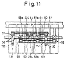
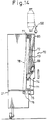
- FIG. 11 The mechanism and function of the lifting device of the peg units 30A and 30B are explained in detail with reference to Figs. 11 to 13.
- Six upright guide rods 56 are arranged between the upper bracket 55a and a lower bracket 55b on the main body 21 of the roving bobbin exchange apparatus 20. These six guide rods 56 are divided into two groups of three arranged alternately.
- a lifting member 57 utilized for the almost exhausted roving bobbin SB is mounted on each guide rod 56 of the first group of the guide rods 56, and a lifting member 58 utilized for the full packaged roving bobbin FB is mounted on each guide rod 56 of the second group of the guide rods 56, such that it can be lifted along the guide rod 56.
- the three lifting members 57 and the three lifting members 58 are connected by respective connecting plates 57b and 58b.
- the above-mentioned bases 45 are respectively connected to connecting portions 57a of the lifting member 57, 58a of the lifting member 58, which extend upward, respectively, such that the right-left pitch between the back pegs 32, 41 of the peg units 30A and 30B, which are positioned adjacently so that the back pegs 41 are at the standby position, coincides with the right-left pitch A2 between two adjacent bobbin hangers 7a or 7b of the front and back row of bobbin hangers 7 of the creel portion 2 of the spinning frame 1.
- a pair of lifting motors 59 are mounted on the main body 21 of the apparatus 20 at the bottom thereof, and a pair of sprocket wheels 60 are rigidly mounted on a motor shaft extended inward from each lifting motor 59. Further, two pairs of sprocket wheels 61 are rotatably mounted on an upper bracket 55a of the main body 21 of the apparatus 20 at positions corresponding to the sprocket wheels 60, and an endless chain 62 is mounted on one of sprocket wheels 60 of each pair of sprocket wheels 60 and corresponding to one of the sprocket wheels 61 of the corresponding lifting motor 59, as shown in Figs. 12 and 13.
- Each of the lifting members 57 and 58 is connected to an intermediate portion of the corresponding endless chain 62 so that the peg units 30A, 30B can be displaced between the standby position thereof (S3 in Fig. 12) and the uppermost position (S4 in Fig. 12) where roving bobbins are mounted on or dismounted from the corresponding bobbin hanger 12 of a bobbin carriage 13 supported by the supplemental rail 11 (Fig. 12) by the motion of the endless chains 62.
- the device for handling almost exhausted roving bobbins SB is formed by the peg unit 30A, the device for displacing the peg units 30A in the front-back direction, and the device for lifting the peg unit 30A
- the device for handling full packaged roving bobbins FB is formed by the peg units 30B, the device for displacing the peg units 30B in the front-back direction, and the device for lifting the peg units 30B.
- a pair of side plates 71 are secured to the bottom surface of the main body 21 of the apparatus, and these side plates 71 are extended upward at the corresponding side of the body 21, respectively.
- Each of the side plates 71 is provided with a guide rod 73 extended to an upper position of the side plate 73 while inclowd thereto, and a slide block 74 is slidably mounted on each of the guide rods 73.
- a sprocket wheel 76 which is driven by a drive motor 75 rigidly disposed on the bottom surface of the main body 21, is rotatably mounted on each side of the main body 21, and another sprocket 77 is rotatably mounted on each side of the main body at respective upper positions thereof.
- An endless chain 78 is mounted on the sprocket wheels 76 and 77 at both sides of the main body 21, and the guide block 74 is connected to the corresponding endless chain 78 at both sides of the main body 21.
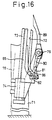
- a pipe 79 is rotatably supported by an upper end of the slide blocks 74 such that the pipe 79 also can slide along the axial direction thereof; one end portion of the pipe 79 being connected to a suction air source (not shown), and the other end portion thereof being rigidly connected to a lever 80, as shown at the left of Fig. 15.
- a free end of the lever 80 is provided with a forked portion having two separate elementary portions 81 and a cam follower 82 is rotatably supported on each of the elementary portions 82.
- These cam followers 82 sandwich a free bottom end 85a of a plate cam 85 secured to a left one of the side plates 71 (see Figs. 15 and 17) disposed at the main body 21 of the apparatus 20.
- the plate cam 85 is designed such that, when the slide blocks 74 are synchronously displaced upward, the pipe 79 is displaced along the axial direction thereof, and takes a position as represented by a chain-row at the upper-most position of the slide blocks 74 in Fig. 15. Namely, the pipe 79 is displaced along the axis thereof by the lifting motion of the slide block 74 and the pitch of the slide motion of the pipe 79 is identical to the pitch A1 between the trumpets of two adjacent draft parts of the spinning frame 1. As shown in Figs.
- each suction nozzle 89 is connected to the pipe 79, and the pitch between two nozzles 89 of each pair is identical to the pitch A1, while the pitch between two adjacent pairs of the suction nozzles 89 is four times the pitch A1,
- the plate cam 85 is provided with a cam groove 72, as shown in Fig. 16, and another cam follower 86 is disposed on the lever 80 perpendicular to the axis of the cam followers 82.
- each suction nozzle 89 can be displaced along a moving trace which prevents any possible interference with the corresponding sliver piecing head 100 during a displacement of the slide blocks 74. Therefore, each of the suction nozzles 89 can be displaced upward and downward while being displaced in the lengthwise direction of the spinning frame 1 between the corresponding standby position S7 and the corresponding position for catching a free end of a roving roving from a full packaged roving bobbin FB.
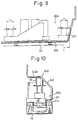
- a horizontal shaft 110 is rotatably mounted on a pair of upright brackets 111 disposed at a front lower portion of the main body 21 of the apparatus 20, and a pair of arms 112 are secured at the ends of the shaft 110 (Fig. 2).
- a shaft portion 101a formed at one end of a supporting bar 101 of the roving piecing head 100 is provided with an arm 112.
- the shaft 101a is projected from the arm 112, and a lever 113 is secured to this projected portion of the shaft 101a.
- the lever 113 is linked to a piston rod 115 of the swing cylinder 114 so that the roving piecing head can be swung between a horizontal position and a vertical position by the swing motion of the swing cylinder 114.
- One end of the shaft 110 is linked to an end of a lever 116, and the other end of the lever 116 is linked to a link lever 118a of a crank mechanism 118, which is driven by a motor 117.
- the arm 112 is provided with a swing motion between a standby position thereof and a terminal point of the forward motion thereof where the roving piecing head 100 is at a roving piecing position S9 while in a horizontal condition.
- the roving piecing head utilized in the apparatus disclosed in Japanese Unexamined Patent Publication No. 62-53425 is utilized.
- the supporting bar 101 of each roving piecing head 100 is secured to a main body 102a of the head 100 at a position facing the suction nozzle 89
- a roving holding lever 103 is mounted on each head body 102a such that it is swingable about a supporting shaft 102
- an actuation lever 105 is rigidly mounted on a bar 104 which can be traversed to the right and left by a cylinger (not shown).
- the roving holding lever 103 is provided with a pin 103a projected toward the actuation lever 105 at a position facing the lever 105, and the lever 105 is provided with a recess for receiving the pin 103a whereby the roving holding lever 103 is forced to swing about the shaft 102 by the traverse motion of the actuation lever 105.
- the above-mentioned mechanism is designed to create a motion of the roving holding lever 103 such that the free end of the lever 103 can be positioned for holding a roving R2 of a full packaged roving bobbin FB while the free end thereof comes into contact with a stopper block 106 secured to the roving piecing head 100, can be positioned holding a roving R1 of an almost exhausted roving bobbin SB while the free end thereof comes into contact with a stopper block 107 secured to the roving piecing head 100, and can be positioned at an intermediate point where the free end thereof does not come into contact with the stopper blocks 106 and 107.
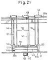
- a pair of upright guide rods 131 are disposed on the main body 21 of the apparatus 20 at the respective positions in front of the guide rods 56, which are positioned at both sides of the row of five guide blocks 56, in a space between the upper and lower brackets 55a, 55b (see Fig. 12).
- a pair of lifting blocks 132 are slidably mounted on the corresponding lifting blocks 132, respectively, and the lifting blocks 132 are connected by a connecting member 142.
- a horizontal swing shaft 133 is rotatably supported by the lifting blocks 132 at an space therebetween.
- the bottom ends of three roving hang bars 134 are secured to the swing shaft 133, an end of a lever 143 is rigidly connected to an end of the swing shaft 133, and a cam follower 143a is mounted on a shaft secured to the other end of the lever 143.
- the cam follower 143 is designed such that it is guided by a cam surface 144a of a plate cam 144 disposed in a space between the main body 21 of the apparatus 20 and the bracket 55a.
- the connecting member 142 is connected to an endless chain 141 mounted on a sprocket wheel 138 rotatably mounted on the upper bracket 55a, and a sprocket wheel coaxially and rigidly mounted on a motor shaft of a lifting motor 139, which is secured to a bottom surface of the main body 21 of the apparatus 20.
- the profile of the cam surface 144a is such that the free end of the roving guide member 145 of the roving hang lever 134 is moved to a position below the front creel by a swing motion thereof as shown in Fig. 28(c), then moved to a roving hanging position above the roving guide 9 as shown in Fig. 29(b), and thereafter, returned to the standby position thereof as shown in Fig. 29(c).
- a pair of guide members 145 are formed at the free end of the roving hang lever 145.
- a pair of air cylinders 147 are arranged at a bracket 146 secured to the upper surface of the free end of the roving hang lever 134 such that the working directions of these air cylinders 147 are reversed, and a forked-shaped roving guide member 145 having a guide recess 145a is secured to the free end of a piston rod 148 of each air cylinder 147.
- the bottom of the roving guide member 145 is provided with a recessed surface, which is mounted on a horn-shaped guide bar 149 secured to the upper surface of the roving hang bar 134 so that each roving guide member 145 is traversed between a position represented by a solid row and a position represented by a chain row as shown in Fig. 22.
- the air cylinder utilized in the first embodiment of the invention is a conventional air cylinder whereby a spring is disposed in the cylinder so that a piston rod is projected outward by the action of the spring when the air cylinder 147 is not actuated. This condition is represented by a solid row in Fig. 22.
- the distance between the roving guide members 145 in the right-left directions is identical to the space A2 between two adjacent full packaged roving bobbing FB, and the recesses 145a of the roving guide members 145 face the respective openings 8 of the corresponding roving guides 9 having a C shape, respectively.
- the device 160 is mounted on the main body 21 at the left of the peg unit 30A which is at the left most side of the row of peg units 30A and 30B in Fig. 2. As shown in Figs.
- a pair of brackets 161a and 161b are secured on an extended portion 21a of the main body 21, and the brackets 161a and 161b are connected by a pair of guide rods 162 arranged in parallel at upper and lower relative positions, and a slide base 163 is slidably mounted on the guide rods 162 so that the slide base 163 can slide forward and backward.
- the slide base 163 is provided with a supporting plate 163a secured thereto at the side of the peg unit 30A and connected to a piston rod 164a of a cylinder 164, which is disposed on the main body along the guide rod 162. As shown in Fig.
- a cylinder 165 is mounted on the supporting plate 163a such that a piston rod 165a is directed upwards, and a peg 166 is disposed at an upper end of the piston rod 165a for mounting a roving bobbin thereon.
- the peg 166 is positioned at a pitch A2 from a front peg 32 of the above-mentioned peg unit 30A in the right-left direction.
- the full packaged roving bobbin FB mounted on the front peg 166 of the sub-peg unit 30A taking the most upstream position of the apparatus 20 with respect to its displacing direction Z takes a position below the supplemental rail 11 at one pitch A2 downstream to the group of almost exhausted roving bobbins suspended by the respective roving hangers of the bobbin carriage on the rail 11.
- full packaged roving bobbins FB and almost half exhausted roving bobbins MB are alternately supported by the bobbin hangers 7a of the front row of the bobbin hangers 7 and by the bobbin hangers 7b of the back row of the bobbin hangers 7 arranged in the creel portion on each side of the ring spinning frame 1, such that the size of a roving bobbin package of any bobbin hanger of the front row thereof is identical to that of the roving bobbin supported by the bobbin hangers which face the corresponding roving hanger of the back row of the roving bobbin hanger.
- the roving bobbin exchange apparatus 20 reaches a working position along the corresponding one side of the spinning frame 1, in a direction from the side of the outer-end frame of the spinning frame 1 [in the direction indicated by an arlow Y in Figs 28(a).....28(b)].
- the apparatus 20 is first stopped at a position in front of the first three pairs P1 of the almost exhausted roving bobbins SB such that the first pair P1 of almost exhausted roving bobbins at a first position in the row of three pairs P1 of the almost exhausted roving bobbins SB faces the first peg unit 30A (utilized for handling almost exhausted roving bobbins SB) at a first position from the left in the row of three peg units 30A among the six peg units of the apparatus 20.
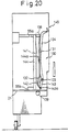
- each of the front pegs 32 of three peg units 30A and three peg units 30B are respectively positioned below the corresponding full packaged roving bobbins FB supported by three successive pairs P2 of the bobbin hangers supported by the supplemental rail 11.
- each unit combination-device provided with the roving piecing head 100 and the suction nozzle 89 faces the pair of trumpets 14 which are supplying the rovings R1 from the corresponding pair P1 of the almost exhausted roving bobbins SB to the corresponding two adjacent draft parts of the ring spinning frame 1, and the pair of the roving guide members 145 face the pair of roving guides 9 which are supplying the above-mentioned rovings R1 respectively.
- three peg units 30B (utilized for handling full packaged roving bobbins FB), are displaced upward from their standby positions S3 to their respective upper end positions S4, and during the above-mentioned lifting motion of the peg units 30B, the swing motors 39 of three peg units 30B are actuated so that each of the swing arms 38 are swung horizontally in the counterclockwise direction in the drawing, through the respective stationary gears 37 and the gears 40, so that the back pegs 41 are displaced to the respective displaced positions S2.
- the full packaged roving bobbins FB supported by the successive three pairs P2 of roving bobbins of the supplemental rail 11, which correspond to almost exhausted roving bobbins SB of the three pairs P1, at respective positions for carrying out the roving bobbin exchange operation in the creel portion 2 of the spinning frame 1, are mounted on the front and back pegs 32 and 41 of the above-mentioned three peg units 30B.
- the motor 75 utilized for lifting the suction nozzle is driven so that the endless chains 78 are driven, the slide blocks 74 are displaced upward along inclined paths created by the guide rods 73, so that the cam follower 82 is guided by the plate cam 85 and the cam follower 86 is guided by the grooved cam 72 formed in the plate cam 85, and accordingly, the suction nozzles 89 are displaced upward together with the upward displacement of the slide blocks 74, by way of the pipe 79, and further, are displaced to the right-left direction (in Fig.
- each suction nozzle 89 is displaced from the standby position S7 to the suction position S8 thereof, and the above-mentioned motion is stopped when each nozzle 89 arrives at the suction position S8, where the free end of each suction nozzle 89 is close to the peripheral surface of the corresponding one of the six full packaged roving bobbins FB.
- each suction nozzle 89 positioned at the suction position S8 starts a suction operation
- the front pegs 32 and back pegs 41 are then rotated slowly by the action of the reversible motors 42 and 39, in the direction of rewinding the roving from the full packaged roving bobbins FB, simultaneously with the start of the actuation of the suction source.
- each suction nozzle 89 sucks a free end of the roving from the corresponding full packaged roving bobbin FB, and then each suction nozzle 89 is displaced from the suction position S8 to the standby position S7 thereof below the corresponding roving piecing head 100, by an action reverse to the above action of the constitutional elements of the apparatus 20, while maintaining the suction.
- the full packaged roving bobbins FB are slowly rotated in the rewinding direction thereof.
- each roving piecing head 100 is swung from a suspended condition to a horizontal condition by the head swing cylinder 114, so that the gripped roving R2 is separated into two portions at a position between the suction nozzle 89 and the corresponding roving piecing head 100, by a comb (not shown) disposed in each suction nozzle 89 [see Fig. 28(c)].
- each roving piecing guide member 145 enters a region of the roving R2 from the corresponding full packaged roving bobbin FB and the corresponding roving piecing head 100, each group of two rovings R2 is separated into a right side and left side on the inclined surface of each roving guide member 145, and the intermediate portion of the roving R2 is positioned in the recess 145a of the corresponding roving guide member 145.
- the arm 112 is displaced to the terminal point of the forward moving motion thereof by actuating the motor 117, and the roving guide member 145 is displaced to a position below the row of almost exhausted roving bobbins SB and the full packaged roving bobbins FB are rotated in the rewinding direction, whereby the roving piecing heads 100 are positioned at respective position above the corresponding trumpets to carry out a roving piecing operation thereat.
- the roving holding lever 103 of the roving piecing heads 100 is displaced to a non-operating position.
- the roving R2 from the full packaged roving bobbin FB is released from the holding action of the roving holding lever 103, and thus the doubled portion of the rovings R1 and R2 is introduced into the trumpet 14, and the roving portion connected to the almost exhausted roving bobbin SB is separated from the doubled portion of the rovings R1 and R2.
- the above-mentioned roving piecing operation is carried out simultaneously at three adjacent pairs of almost exhausted roving bobbins of the creel portion at one side of the ring spinning frame 1 [see Fig. 28(d)].
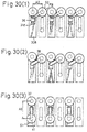
- each peg unit 30B is brought into contact with the intermediate block 31d of the identical peg unit 30B, while maintaining the swing angle of the swing arm 38, so that the arrangement of the full packaged roving bobbins FB aligned [see Fig. 20(e)] at a position below the supplemental rail 11 is changed to a zig-zag condition as shown in Fig. 30(2).
- each swing arm 38 is turned so that corresponding back peg 41 is returned to the original position S1, whereby the relative arrangement of two adjacent full packaged roving bobbins FB is changed to the arrangement condition represented by P1 [Fig. 30(3)].
- the radius of the swing motion of the full packaged roving bobbin FB mounted on the back peg of each supporting body 36 is reduced by an extent of the forward displacement motion of the supporting body 36, and therefore, even though the diameter of the full packaged roving bobbin FB is large and is close to the pitch A2, the change of the arrangement of the full packaged roving bobbins FB can be carried out without interference thereby with the full packaged roving bobbin FB mounted on the corresponding front peg 32.
- each roving holding lever 103 grips a roving R1 from the corresponding almost exhausted roving bobbin SB, by holding the same in a space between the corresponding stopper block 107, whereby the connection of the roving R1 to the almost exhausted roving bobbin SB is broken by feeding the roving R1 into the corresponding draft part of the spinning frame 1.
- the drive motor 50 for actuating the front-back displacing motion of the peg units 30A is driven to displace the peg units 30A forward, and due to this displacement motion of the peg units 30A, the front and back pegs of these peg units 30A are positioned at the respective positions below the corresponding pair P1 almost exhausted roving bobbins SB [see Fig.
- each doubled portion of the roving R2 is introduced to the side of the corresponding peg unit 30A by the guide portion of the roving separation guide 240 or the front-back bar 241 of the corresponding roving piecing head 100.
- each peg unit 30A positioned below the almost exhausted roving bobbins SB is displaced upward and downward so that the almost exhausted roving bobbins SB of corresponding front-back pair P1 are taken from the respective bobbin hangers 7 of the creel portion 2 of the spinning frame 1 and are mounted on the corresponding front and back pegs 32 and 41 of the peg unit 30A.
- the almost exhausted roving bobbins SB are rotated in the winding direction by rotating these pegs 31 and 41, and accordingly, the rovings R1 separated from the respective rovings introduced to the corresponding draft parts are wound thereon [see Fig. 28(f)].
- each peg unit 30A holding the almost exhausted roving bobbins SB is displaced backward so that each pair of almost exhausted roving bobbins SB, while maintaining the P1 relationship thereof, are positioned at respective positions adjacent to the corresponding front-back pair P1 of the full packaged roving bobbins FB.
- the above explanation concerns a roving bobbin exchange operation applied to bobbin hangers in an intermediate portion of the row of the bobbin hangers, as shown in Fig. 29(a), the peg 166 located at a position right below the almost exhausted roving bobbin, which is suspended by the corresponding bobbin hanger of the bobbin carriage of the supplemental rail 11 is taken from the bobbin hanger by displacing upwards and the downwards and thereafter the above-mentioned almost exhausted roving bobbin is transferred to the waiting position S6.
- each roving piecing head 100 is returned to the standby position in the vertical condition, and each roving guide member 145 is displaced upward so that each roving R2 located at a position downstream of the corresponding roving guide member 145 is introduced into the corresponding roving guide 9 from the opening 8 thereof.
- the corresponding two guide members 145 are displaced toward each other by the action of the two air cylinders 147, and the roving guide member 145 is retracted so that the rovings R2 are hung inside the hook portions 9a of the corresponding roving guides 9, respectively, as shown in Fig. 29(b) and Fig. 25 (indicated by two-dot row).
- each pair P1 of front-back full packaged roving bobbins FB on the three peg units 30B of the apparatus 20 are respectively positioned facing the corresponding pair of bobbin hangers 7a and 7b of the creel portion 2 of the spinning frame 1, from which the almost exhausted roving bobbins SB were taken off [see Fig.
- each peg unit 30B having the full packaged roving bobbins FB is displaced forward, to take the corresponding front-back bobbin hangers 7a, 7d of the creel portion 2 of the spinning frame 1, and these peg units 30B are then displaced upward and downward to transfer the full packaged roving bobbins FB from the pegs of the peg units 30B to the corresponding bobbin hangers 7a or 7b of the creel portion 2 of the spinning frame 1 [see Fig.
- each peg unit 30A supporting the almost exhausted roving bobbins SB is displaced upward, while the corresponding swing arms 35 are turned so that the back peg 41 of each peg unit 30A is angularly displaced from the original position S1 to the displaced position S2, with the almost exhausted roving bobbin SB mounted thereon.
- the arrangement of the three pairs P1 of front-back almost exhausted roving bobbins SB is changed to an arrangement of three pairs P2, having a right-left relationship, of the respective two almost exhausted roving bobbins SB, i.e., one row of almost exhausted six roving bobbins SB, and accordingly, these almost exhausted roving bobbins SB are easily transferred to the bobbin hangers 12 of the supplementary rail 11 [see Fig. 29(e)].
- the above-mentioned unit roving bobbin exchange operation is repeated by displacing the apparatus by a unit pitch which is six times the pitch between two adjacent bobbin hangers 7a (7b) of the two parallel rows thereof in the creel portion 2 of the spinning frame, toward the left side, and the unit roving bobbin exchange operation is carried out when the apparatus is stopped after one displacement thereof.
- each step of the roving bobbin exchange operation the main body 21 of the apparatus 20 may be held at each working position for carrying out one unit roving bobbin exchange operation thereof and while being held, each peg unit, formed by a first sub-peg unit and second sub-peg unit, may move one pitch A2 along the spinning frame 1.
- the main body 21 of the apparatus which supports a roving bobbin at the position S6, may move one pitch A2 along the spinning frame 1 at the above-mentioned working position.
- the above-mentioned peg units do not undergo the above-mentioned displacing motion along the spinning frame 1.
- the apparatus 20 is stopped at each predetermined position [see Fig. 31(a)], then three successive pairs of full packaged roving bobbins FB are taken from the bobbin hangers 13 (not shown) of the bobbin carriage 12 (not shown) of the supplemental rail 11 (not shown) and displaced on the pegs of the corresponding sub-peg unit 30A (30B) of the apparatus 20 (not shown).
- three pairs of almost exhausted roving bobbins SB are taken from the bobbin hangers of the spinning frame 1 and mounted on the corresponding pegs of the corresponding sub-peg unit 30A mounted on the apparatus 20.
- sub-peg units 30A take the respective positions shown in Fig. 31(b). Thereafter, a full packaged roving bobbin FB, supported by a bobbin hanger of the supplemental rail 11 (not shown) at a position adjacent to a bobbin hanger, supporting a full packaged roving bobbin FB at a position right above an outside peg of a first sub-peg unit 30A of the three sub-peg units 30A of the apparatus 20 (not shown) in the displacing direction of the apparatus 20 (not shown) is taken from the above-mentioned bobbin hanger of the supplemental rail 11 and the displaced to the standby position S6 on the apparatus 20 (not shown).
- the apparatus 20 (not shown) is displaced by one pitch A2 in the Z direction in Fig. 31(b), and thereafter a pair of full packaged roving bobbins FB are mounted on the corresponding outside and inside bobbin hangers 7a, 7b (not shown) of the spinning frame 1.
- These full packaged roving bobbins FB are displaced by the action of the pegs of the sub-peg units 30A as shown in Fig. 31(c).
- each pair of almost exhausted roving bobbins SB is changed to an arrangement along the lengthwise direction of the supplemental rail 11 (not shown) and then the apparatus 20 (not shown) is displaced toward a direction Za Fig 31(c) opposite to the direction Z and mounted on the corresponding bobbin hangers of the supplemental rail 11 (not shown). This condition is indicated in Fig. 31(d).
- the first unit operation is carried out in the mode identical to that of the above-mentioned first embodiment of the present invention, in other words, the first unit operation does not involve the process of temporarily transferring the almost exhausted roving bobbins on the corresponding bobbin hangers of the supplemental rail 11 and the process of returning the roving bobbins to the corresponding bobbin hangers of the supplemental ring 11.
- the processes from the operation of taking six full packaged roving bobbins from the bobbin hangers of the supplemental rail 11 to the operation of mounting the full packaged roving bobbins FB on the corresponding pair of bobbin hangers 7a, 7b are identical to the first embodiment as shown Figs.
- the roving bobbin exchange operation is started from the condition indicated in Fig. 33(a) wherein an almost exhausted roving bobbin SB is positioned at the standby position S6, and the processes indicated in Figs. 28(b) to Fig. 28(f) are carried out.
- the almost exhausted roving bobbins SB are taken from the bobbin hangers of the creel portion of the spinning frame and the sub-peg units take their original positions on the apparatus 20
- the full packaged roving bobbins FB supported by the respective sub-peg units 30B take their respective positions right below the corresponding bobbin hangers of the spinning frame 1 [see Fig.33(b)].
- the almost exhausted roving bobbin SB supported by the peg of the back side is displaced to a position in a row of the almost exhausted roving bobbins SB supported by the pegs of the front side of the sub-peg units 30B so that six successive almost exhausted roving bobbins SB take the positions right below the corresponding bobbin hangers of the supplemental rail 11.
- the apparatus 20 is not displaced. In this condition, the above-mentioned six almost exhausted roving bobbins SB are successively mounted to the bobbin hangers 12 of the supplemental rail 11 as shown in Fig. 33(c).
- the almost exhausted roving bobbin SB positioned at the standby position S6 is returned to a free bobbin hanger 12 of the supplemental rail 11 simultaneously so that the unit roving exchange operation is completed [see Fig. 34(b)].
- the apparatus 20 is not displaced after the full packaged roving bobbins FB are mounted on the bobbin hangers 7(7a, 7b) in the creel portion 2 of the ring spinning frame 1, the time required for the operation of correctly positioning the apparatus 20 at each time of step displacing motion thereof is reduced so that the time required to complete the entire operation of exchanging the roving bobbing in the spinning frame 1 is reduced.
- the almost exhausted roving bobbin supported by the outside bobbin hanger 7a of a pair of bobbin hangers (outside and inside) of the spinning frame 1, which take a position facing the first one of three sub-peg units 30B in the direction of displacing the apparatus 20, is temporarily reserved in the apparatus 20.
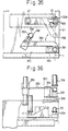
- the above-mentioned device 260 is provided with a base 261, an arm 262 which is turnably mounted on the base 261 in a horizontal condition, and a gripper 263, which is provided with two gripping fingers, secured to the free end portion of the arm 262.
- the horizontal swing motion of the arm 262 is actuated by a motor 254 secured to the base 261 by way of the gear train 265 so that the swing motion of the gripper 263 between a position S5, positioned right above the front peg 32 of the second sub-peg unit 30A which is located at the end portion of the apparatus 20 with respect to the direction of the displacement of the apparatus 20, and the standby position S6 positioned left from a position right below the supplemental rail 11, is created.
- the height of the device 260 is so designed that the apparatus 20 is capable of passing through a space below the roving bobbins suspended by the bobbin hangers of the supplemental rail 11.
- the roving bobbin exchange method utilized by the apparatus 20 provided with the above-mentioned device 260 is explained in detail below, however, only the characteristic features different from the above-mentioned method explained already are explained.
- Each sub-peg unit 30A whereon a pair of almost exhausted roving bobbins SB is mounted is displaced to the corresponding position adjacent to the corresponding sub-peg unit 30B whereon a pair of full packaged roving bobbins FB is mounted.
- the almost exhausted roving bobbin SB, which is supported by the front peg of the first sub-peg unit 30A of the apparatus located at the displacing direction of the apparatus 20 is gripped by the gripping elements of the gripper 263 of the device 260.
- the peg unit 30A is displaced downward while maintaining the above-mentioned gripping condition by the gripper 263, toward its standby position, so that the almost exhausted roving bobbin SB is taken from the front peg 32 of the sub-peg unit 30A, so that the almost exhausted roving bobbin SB is transferred to the standby position S6 by the action of the arm 262 [see Fig. 37(a)].
- the main body 21 of the apparatus 20 is displaced by one pitch A2 so that the pair of full packaged roving bobbins FB mounted on each sub-peg unit 30B faces the corresponding pair of outside and inside bobbin hangers 7a and 7b from which the almost exhausted roving bobbins have been taken off [see Fig.
- the almost exhausted roving bobbin SB reserved at the standby position S6 is returned to the front peg 32 of the sub-peg unit 30A positioned at the right end side of the apparatus 20 by the swing motion of the arm 262, the gripping operation of the gripper 263, and the upward motion of the sub-peg unit 30A, and then the apparatus 20 is displaced to the left direction [in Fig. 37(c), upward direction indicated by an arlow] along the spinning frame by one pitch A2, which is a pitch between the bobbin hangers of the spinning frame 1.
- the sub-peg units 30A holding the almost exhausted roving bobbins SB are simultaneously displaced upward, while the swing arm 38a is turned so that the back peg 41 holding the almost exhausted roving bobbin SB is displaced from its original position S1 to the displaced position S2. Accordingly, the arrangement of the almost exhausted roving bobbins SB of each sub-peg unit 30A is changed to a right-left arrangement thereof, in other words, six almost exhausted roving bobbins SB supported by the sub-peg units 30A are arranged in a row along the supplemental rail 11.
- the unit operations are different from each other between the first unit portions, the last unit operation, and the intermediate unit operation between the first and last unit operations. That is, in the first unit operation, after the full packaged roving bobbins FB are mounted on the pegs of the sub-peg units 30A, the almost exhausted roving bobbins SB standing by at the position S6 are not returned to the front peg 32 of the sub-peg unit 30A positioned at the right end side of the apparatus 20. On the other hand, the apparatus 20 is not displaced to the left side direction by one pitch A2.
- the arrangement of two almost exhausted roving bobbins SB mounted on the front and back pegs 32, 41 of each sub-peg unit 30A is changed to the arrangement along the right and left direction at the positions on the apparatus 20.
- These almost exhausted roving bobbins SB are mounted on the bobbin hangers of the supplemental rail 11. Accordingly, five almost exhausted roving bobbins SB, which are suspended from the bobbin hangers of the supplemental rail 11 as mentioned above, from the right side end [upper side in Fig. 38(a)] of the apparatus 20 are positioned facing the corresponding one of the five pairs of outside and inside bobbin hangers of the spinning frame 1, respectively.
- the roving exchange operation is started with the almost exhausted roving bobbin SB reserved at the standby position S6 on the apparatus 20.
- the full packaged roving bobbins FB face to the corresponding front and back bobbin hangers of the spinning frame 1, from which the almost exhausted roving bobbins SB have been taken off, by the operation of the sub-peg units 30B, without displacing the apparatus 20 along the lengthwise direction of the spinning frame 1.
- each sub-peg unit 30A is returned to its original position and the apparatus 20 is simultaneously displaced to the right side direction by one pitch A2. Then, the above-mentioned three peg units 30A are displaced upward so that two almost exhausted roving bobbins SB indicated by hatching in Fig. 38(b) are taken from the bobbin hangers of the supplemental rail 11, the almost exhausted roving bobbin SB which has been reserved in the apparatus 20 is returned to the front peg 32 of the sub-peg unit 30A positioned at the right end of the apparatus 20, and three exhausted roving bobbins SB are mounted on the corresponding bobbin hangers of the supplemental rail 11.
- the following modification can be applied, that is, one supplemental bobbin hanger is additionally mounted on the supplemental rail 11 so that the operation for transferring one roving bobbin to the standby position in the apparatus 20 in the first unit operation and the operation for transferring the roving bobbin from the standby position on the apparatus to the bobbin hanger of the supplemental rail 11 and the one pitch A2 apparatus 20 in the first and the last unit operations can be omitted.
- a pair of horizontal guide rods 211a and 211b extending in the front and back direction are roughly disposed on the main body 21 at an intermediate position between the sub-peg unit 30A and the sub-peg unit 30B.
- a sliding body 212 is slide along the front and back direction on the guide rods 211a and 211b.
- the guide rod 211a is provided with a worm rack 213 at the bottom portion thereof along the lengthwise direction, which worm rack 213 meshed with a worm gear 215 of a drive motor 214.
- a bottom of a pillar 212a is rotatably mounted on the side body 212.
- a gear 216 is formed at the bottom end of the pillar 212a as one body thereto meshed with a drive gear 218 of a torque motor 217.
- a suspension arm 219 is connected at its bottom portion to the upper end of the pillar 212a.
- An engaging member 220 is formed at the free end portion of the suspension arm 219 for suspending a roving bobbin by engagement thereto.
- the turning angle of the suspension arm 219 is designed such that, when the suspension arm 219 is turned in a condition maintaining its position at the terminal point of its backward displacement in the front and back direction or at the terminal point of the forward displacement in the front and back direction, the engaging portion 220 takes a position right above the back peg 41 or the front peg 32 of the sub-peg units 200A, 200B which form a pair.
- the bobbin transferring device 210 six full packaged roving bobbins are displaced downward to the respective standby positions corresponding to the standby position S3, by simultaneously displacing six sub-peg units 200A and 200B upwards.
- the arm 219 is then turned counterclockwise at the terminal position of the above-mentioned forward motion, and the engaging portion 220 engages with an upper flange 221 of the corresponding full packaged roving bobbin FB mounted on the corresponding sub-peg unit 200A which is mainly utilized for the almost exhausted roving bobbins SB. Thereafter, six sub-peg units 200A and 200b are simultaneously displaced downward, the full packaged roving bobbin Fb mounted on the above-mentioned sub-peg unit 200A are transferred to the engaging portion 220 of the respective suspension arms 219 so that an intervened space is created between the bottom of each suspended full packaged roving bobbin FB and the corresponding peg 32 or 41 of the sub-peg unit 200A.
- each suspension arm 21 is displaced backward and turned counterclockwise at the terminal position of the above-mentioned backward displacing motion thereof, and this turning motion is stopped when the axial position of the full packaged roving bobbin FB coincides to the axial row of the back peg 41 of the sub-peg unit 200B, which is mainly utilized for the full packaged roving bobbin FB.
- the position of the suspended full packaged roving bobbin FB of course takes a position above the above-mentioned back peg 41 of the sub-peg unit 200B.
- each right and left pair arrangement of the full packaged roving bobbins on the corresponding sub-peg unit 200B is changed to an arrangement of a front back relation so that three pairs P1 of full packaged roving bobbins FB arranged in the front and back relation are created. If the arrangement of almost exhausted two roving bobbins SB in the front and back relation is required to the arrangement in the relation of right and left, the successive operations reverse to the above-mentioned successive operations are applied.
- a device for temporarily holding roving bobbins to prevent possible interference between the roving bobbins in the apparatus with the roving bobbins of the supplemental rail, however, such a device and the operations related to such a device can be omitted by arranging the supplemental rail at a position high enough to prevent the above-mentioned interference during the successive operations to carry out the roving bobbin exchange operation.
- the unit operation of carrying out the roving bobbin exchange operation which is applied to a pair of two roving bobbins facing each other in the creel portion of a spinning frame, can be satisfactorily performed in a limited working space defined by double the pitch between two adjacent bobbin hangers of front or back row of bobbin hangers a long the lengthwise direction of the spinning frame. Therefore, a number of unit roving bobbin exchange operations can be simultaneously carried out to a corresponding plurality of successive pairs of almost exhausted roving bobbins of the creel portion of a spinning frame with the full packaged roving bobbins of the supplemental rail. Accordingly, the most remarkable advantage of the present invention is to be able to remarkably reduce the time required to complete the entire roving bobbin exchange operation in a spinning frame.
- the position of the supplemental relative to the creel portion of the spinning frame can be made lower than in the conventional system because before the apparatus is displaced by one pitch in the lengthwise direction of the spinning frame so as to each made pair of front and back full packaged roving bobbins mounted on the sub-peg units the corresponding pair of bobbin hangers (front and back roving bobbins facing each other) of the creel portion of the spinning frame, from which the almost exhausted roving bobbins have been taken off, a front roving bobbin of a first sub-peg unit located at an end of the apparatus with respect to the displacing direction thereof, or a roving bobbin of the supplemental rail which is adjacent to a roving bobbin of the supplemental rail facing the above-mentioned roving bobbin of the sub-unit peg in the displacing direction of the roving bobbin exchange apparatus, is transferred to a standby position separated from a position right below the supplemental rail.
- the arrangement height of the supplemental rail can be designed a little lower than the level of arranging the bobbin hangers on the creel portion of the spinning frame.
- the level difference between the roving bobbins of the creel portion of the spinning frame and the roving bobbins of the supplemental rail becomes small, the lifting distance of the roving bobbins at the time of carrying out the roving bobbin exchange operation can be reduced.
- the advantage of the present invention contributes to concerning the speed of the roving bobbin exchange operation.
- the position of the supplemental rail can be designed to lower positions as mentioned above, the arrangement position of the bobbin hangers of the supplemental rail can be at almost the same level as the arrangement of bobbin hangers of the creel portion of the spinning frame, so the roving bobbin exchange operation according to the present invention can be carried out very effectively in a more stable condition.
Landscapes
- Engineering & Computer Science (AREA)
- Mechanical Engineering (AREA)
- Textile Engineering (AREA)
- Spinning Or Twisting Of Yarns (AREA)
Claims (17)
- Procédé de changement de bobines de mèches pour un métier à filer à anneaux muni d'une pluralité d'éléments d'étirage (15) disposés sur une ligne dans la direction longitudinale dudit métier à filer (1) de chaque côté de celui-ci avec un pas (A1) identique, une portion de cantre (2) positionnée au-dessus de ladite ligne desdits éléments d'étirage de chaque côté dudit métier à filer (1), deux rangées parallèles d'organes de suspension de bobines (7) disposées dans ladite portion de cantre (2) le long de ladite ligne d'éléments d'étirage (15) de manière que l'une desdites rangées d'organes de suspension de bobines (7) se trouve du côté intérieur dudit métier à filer, tandis que l'autre rangée desdits organes de suspension de bobines (7) se trouve du côté extérieur dudit métier à filer, dans lequel ledit côté intérieur et les côtés extérieurs dudit métier à filer forment un côté arrière et un côté avant dudit métier à filer respectivement, lesdits organes de suspension de bobines (7) sont disposés avec un pas identique (A2) entre deux organes de suspension de bobines adjacents (7) sur chaque rangée de ceux-ci, alors qu'une distance intermédiaire entre lesdites deux rangées d'organes de suspension de bobines (7) est prévue avec un pas (A3), un rail supplémentaire (11) placé dans une position extérieure à proximité de ladite portion de cantre (2) le long de ladite ligne de broches de chaque côté dudit métier à filer (1) et pouvant recevoir un porte-bobines (13) muni d'une pluralité d'organes de suspension de bobines (12) disposés en rang avec ledit pas (A2); dans lequel(a) des bobines de mèches pleines (FB) sont suspendues alternativement sur des paires respectives d'organes de support de bobines (7) sur une ligne desdites paires d'organes de suspension de bobines (7) dans la direction longitudinale dudit métier à filer (1), chaque paire desdits organes de suspension (7) étant formée d'un organe de suspension de bobine avant (7a) de ladite rangée avant d'organes de suspension de bobines (7) et un organe de suspension de bobine arrière (7b) de ladite rangée arrière d'organes de suspension de bobines (7) qui est vis-à-vis dudit organe de suspension de bobine avant (7a) dans une direction perpendiculaire à la direction longitudinale dudit métier à filer (1),(b) des bobines de mèches presque à moitié vides (MB) sont suspendues alternativement sur des paires respectives restantes desdits organes de suspension de bobines (7a, 7b) de ladite portion de cantre (2),(c) l'opération de filage débute dans lesdits états (a) et (b),(d) ledit porte-bobines (13) auquel lesdites bobines de mèches pleines sont suspendues et porté par ledit rail supplémentaire (11), avant que lesdites bobines de mèches à moitié vides (MB) deviennent des bobines de mèches presque vides (SB) respectivement,(e) une opération de changement de bobines de mèches par groupes est effectuée sur les bobines de mèches presque vides (SB) lorsque lesdites bobines de mèches presque à moitié vides (MB) deviennent des bobines de mèches presque vides (SB) et lesdites bobines de mèches pleines (FB) deviennent lesdites bobines de mèches à moitié vides (MB),(f) ladite opération de changement de bobines de mèches par groupes est effectuée sur toutes les paires d'organes de suspension de bobines (7a, 7b) supportant une bobine de mèche presque vide (SB) dans ladite portion de cantre de chaque côté dudit métier à filer (1) au moyen d'un appareil de changement de bobines de mèches, caractérisé en ce qu'on effectue simultanément ladite opération par groupes à un groupe de paires successives desdits organes de suspension de bobines (7a, 7b) portant lesdites bobines de mèches presque vides (SB) des groupes étant disposés des deux côtés dudit métier à filer (1) dans sa direction longitudinale,
ladite opération, par groupes, est exécutée comme suit:(1) on enlève une paire de deux bobines de mèches pleines (FB), desdits organes de suspension de bobines pleines (12) dudit porte-bobines (13) situé en position de travail sur ledit rail supplémentaire (11) qui correspond à une paire desdits organes de suspension de bobines avant et arrière (7a, 7b) supportant lesdites bobines de mèches presque vides (SB) dans ladite portion de cantre (2) dudit métier à filer (1) et on déplace ces bobines de mèches pleines (FB) dans des positions prédéterminées sur lesdits appareils de changement de mèches le long dudit rail supplémentaire (11);(2) on change la disposition relative des deux bobines de mèches pleines (FB) de ladite rangée le long dudit rail supplémentaire (11) dans une relation avant arrière perpendiculaire à ladite direction longitudinale dudit métier à filer (1) en déplaçant une desdites bobines de mèches pleines (FB) dans une position prédéterminée d'une autre rangée qui est (i) une position du côté avant et (ii) une position du côté arrière par rapport à l'autre desdites bobines de mèches pleines (FB);(3) on enlève les bobines de mèches presque vides (SB) de ladite paire correspondante d'organes de suspension de bobines avant et arrière (7a, 7b) de ladite portion de cantre (2) et on déplace cette paire de bobines de mèches presque vides (SB) dans des positions prédéterminées respectives le long de ladite rangée de bobines de mèches pleines (FB) sur ledit appareil de changement de bobines de mèches, tout en maintenant ladite relation avant arrière desdites bobines de mèches presque vides (SB);(4) on monte ladite paire de bobines de mèches pleines (FB), déplacées dans lesdites positions prédéterminées respectives, sur l'une, correspondante desdites paires d'organes de suspension de bobines avant et arrière (7a, 7b) desquelles lesdites bobines de mèches presque vides ont été enlevées;(5) on change la disposition relative avant-arrière de ces deux bobines de mèches presque vides (SB) par rapport à ladite disposition le long dudit rail supplémentaire (11) en déplaçant l'une desdites bobines de mèches presque vides (SB) d'un côté ou de l'autre desdites bobines de mèches presque vides (SB) dans ladite direction longitudinale dudit métier à filer (1), tout en prenant position sur ledit appareil de changement de bobines de mèches, et ensuite, on monte ladite paire de bobines de mèches presque vides (SB) sur des organes de suspension de bobines correspondants (12) dudit porte-bobines (13). - Procédé de changement de bobines de mèches selon la revendication 1, caractérisé en ce que
ladite opération simultanée par groupes est exécutée sur trois paires d'organes de suspension de bobines avant et arrière (7a, 7b) portant les bobines de mèches presque vides (SB) qui forment une partie dudit groupe de paires successives desdits organes de suspension de bobines (7a, 7b). - Procédé de changement de bobines de mèches selon la revendication 2, caractérisé en ce queledit porte-bobines (13) comporte un organe de suspension de bobine (12) supplémentaire disposé, avec ledit pas (A2) sur ledit porte-bobines (13) dans une position en avant d'un organe de suspension de bobines (12) situé à une extrémité dudit agencement desdits organes de suspension de bobines (12) dans une direction opposée à une direction de déplacement dudit appareil de changement de bobines de mèches le long dudit métier à filer (1),pendant ladite étape (1) de ladite opération par groupes, ladite paire de bobines de mèches pleines (FB) est déplacée vers lesdites positions prédéterminées respectives directement au-dessous dudit rail supplémentaire (11) sur ledit appareil de changement de bobines de mèches, à la suite de quoi une desdites paires de bobines de mèches pleines (FB) est vis-à-vis desdits organes de suspension de bobines avant (7a) de ladite paire d'organes de suspension de bobines (7a, 7b) portant lesdites bobines de mèches presque vides (SB) dans une direction perpendiculaire à ladite direction longitudinale dudit métier à filer (1), tandis que l'autre desdites bobines de mèches pleines (FB) est vis-à-vis desdits organes de suspension de bobines avant (7a) d'une paire desdits organes de suspension avant et arrière (7a, 7b) portant des bobines de mèches presque à moitié vides (MB) situées dans une position le long de ladite paire d'organes de suspension avant et arrière (7a, 7b) portant lesdites bobines de mèches presque vides (SB),pendant ladite étape (4) de ladite opération par groupes, lesdites bobines de mèches pleines (FB) et ladite paire de bobines de mèches presque vide (SB) positionnées dans lesdites positions prédéterminées respectives sont déplacées simultanément dudit pas (A2) de chaque côté dudit métier à filer (1) dans sa direction longitudinale, tout en maintenant la disposition relative desdites paires desdites bobines de mèches pleines (FB) et desdites bobines de mèches presque vides (SB) par quoi ladite paire de bobines de mèches pleines (FB) est vis-à-vis de ladite paire d'organes de suspension de bobines avant et arrière (7a, 7b) de laquelle lesdites bobines de mèches presque vides (SB) sont enlevées dans ladite direction perpendiculaire à ladite direction longitudinale dudit métier à filer (1),pendant ladite étape (5) de ladite opération par éléments, une bobine de ladite paire de bobines de mèches presque vides (SB) positionnée d'un côté dudit métier à filer (1) sur ledit appareil de changement de bobines de mèches est maintenue dans sa position, l'autre bobine de ladite paire de bobines de mèches presque vides (SB) est déplacée horizontalement dans une position située sur une ligne le long dudit rail supplémentaire (11), du côté du déplacement simultané de ladite paire de bobines de mèches pleines (FB) et de ladite paire de bobines de mèches presque vides (SB), alors que la distance axiale entre lesdites bobines de mèches presque vides (SB) est changée de (A3) à (A2),ensuite, ladite paire de bobines de mèches presque vides (SB) est suspendue par ladite paire d'organes de suspension de bobines (12) dudit porte-bobines (13), dont les organes sont positionnés dans des positions respectives en biais à partir des positions respectives de ladite paire d'organes de suspension de bobines (12) de laquelle cette paire de bobines de mèches pleines (FB) a été enlevée, à une distance égale audit pas (A2), dans une direction opposée à la direction dudit déplacement simultané de ladite paire de bobines de mèches pleines (FB) et de ladite paire de bobines de mèches presque vides (SB).
- Procédé de changement de bobines de mèches dans un métier à filer à anneaux, selon la revendication 3, caractérisé en ce quependant ladite étape (4) de ladite opération par groupes, avant le déplacement simultané de ladite paire de bobines de mèches presque vides (SB) dudit pas (A2) dans la direction horizontale le long dudit rail supplémentaire (11), une bobine de mèche pleine (FB) située dans une position juste en dehors de trois paires d'organes de suspension de bobines successifs (7a, 7b) desquelles lesdites bobines de mèches pleines (FB) ont été enlevées, est déplacée en position d'attente éloignée d'une position directement au-dessous dudit rail supplémentaire (11) sur ledit appareil de changement de bobines de mèches, etpendant ladite étape (5) de ladite opération par groupes, lorsque ladite paire de bobines de mèches presque vides (SB) sont déplacées dans une direction opposée à son déplacement horizontal dans l'étape (4) de ladite opération par groupes, ladite bobine de mèches pleine (FB) en réserve temporaire dans ladite position d'attente est ramenée audit organe de suspension de bobine (12) dudit porte-bobines (13) duquel lesdites bobines de mèches pleines étaient enlevées.
- Procédé de changement de bobines de mèches d'un métier à filer à anneaux selon la revendication 3, caractérisé en ce quependant ladite étape (4) de ladite opération, avant le déplacement simultané de ladite paire de bobines de mèches presque vides (SB) dudit pas (A2) dans ladite direction dans le sens longitudinal dudit métier à filer (1) ladite bobine de mèche (SB) qui est située d'un côté dudit métier à filer (1) dans ladite paire de bobines de mèches presque vides (SB), positionnée du côté de déplacement du mouvement simultané dudit groupe formé de paires desdites bobines de mèches pleines (FB) et de paires desdites bobines de mèches presque vides (SB) est mise temporairement en réserve dans une position d'attente sur ledit appareil de changement de bobines de mèches, qui est en dehors d'une position juste au-dessous dudit rail supplémentaire (11),pendant ladite étape (5) de ladite opération par groupes lorsque ladite paire de bobines de mèches presque vides (SB) est déplacée dans une direction opposée audit déplacement horizontal desdites paires de bobines de mèches pleines (FB) et desdites paires de bobines de mèches presque vides (SB) le long dudit rail supplémentaire (11) d'une distance identique audit pas (A2), ladite bobine de mèche presque vide (SB), réservée dans ladite position d'attente est ramenée vers ladite position avant d'être mise en réserve dans ladite position d'attente.
- Procédé de changement de bobines de mèches selon la revendication 1, caractérisé en ce quependant ladite étape (2) de ladite opération par groupes selon laquelle ladite disposition relative de ladite paire de bobines de mèches pleines (FB),prises sur ledit porte-bobine (13) le long dudit rail supplémentaire (11) est changée pour ledit agencement relatif de ladite paire de bobines de mèches pleines (FB) dans une direction perpendiculaire à ladite direction longitudinale dudit métier à filer (1),une distance axiale entre ladite paire de bobines de mèches pleines (FB) est changée dudit pas (A2) à un pas (A3) etpendant ladite étape 5) de ladite opération par groupes selon laquelle ladite disposition relative de ladite paire de bobines de mèches presque vides (SB) prise sur ladite paire correspondante d'organes de suspension de bobines avant et arrière (7a), 7b) est changée dans ladite direction perpendiculaire à ladite direction longitudinale le long dudit rail supplémentaire (11) ladite distance axiale entre lesdites bobines de mèches presque vides (SB) est changée dudit pas (A3) audit pas (A2).
- Procédé de changement de bobines de mèches selon la revendication 1, caractérisé en ce quependant ladite étape (3) de ladite opération par groupes, une extrémité libre avant d'une mèche (R2) est prise de chacune desdites bobines de mèches pleines (FB) positionnées auxdites positions prédéterminées respectives sur ledit appareil de changement de bobines de mèches, avant l'enlèvement de ladite paire de bobines de mèches (SB) d'une paire correspondante d'organes de suspension de bobines avant et arrière (7a, 7b) de ladite portion de cantre dudit métier à filer, etladite extrémité libre avant de ladite mèche (R2) est rattachée à une mèche correspondante (R1) qui est amenée depuis une desdites bobines de mèches presque vides (SB) à un des éléments d'étirage correspondant dudit métier à filer (1).
- Procédé de changement de bobines de mèches selon la revendication 1, caractérisé en ce quependant ladite étape (1) de ladite opération par groupes, ladite paire de bobines de mèches pleines (FB) est déplacée dans des positions respectives prédéterminées directement au-dessous dudit rail supplémentaire (11) sur ledit appareil de changement de bobines de mèches, de telle sorte qu'une bobine de ladite paire de bobines de mèches pleines (FB) est vis-à-vis de l'organe de suspension de bobine avant (7a) d'une première paire d'organes de suspension de bobines (7a, 7b) portant lesdites bobines de mèches presque vides (SB) dans une direction perpendiculaire à ladite direction longitudinale dudit métier à filer (1), tandis que l'autre desdites bobines de mèches pleines (FB) est vis-à-vis dudit organe de suspension de bobines (7a) d'une seconde paire d'organes de suspension de bobines (7a, 7b) portant les bobines de mèches presque à moitié vides (MB) situées en position adjacente à ladite première paire d'organes de suspension de bobines (7a, 7b) dans ladite direction longitudinale dudit métier à filer (1),pendant ladite étape (4) de ladite opération par groupes, ladite paire de bobines de mèches pleines (FB) et ladite paire de bobines de mèches presque vides (SB) positionnées dans lesdites positions prédéterminées respectives sont déplacées simultanément dudit pas (A2) de part et d'autre dudit métier à filer (1) dans sa direction longitudinale, tout en maintenant la disposition relative desdites paires desdites bobines de mèches pleines (FB) et desdites bobines de mèches presque vides (SB), d'où ladite paire de bobines de mèches pleines (FB) est vis-à-vis de ladite paire d'organes de suspension avant et arrière (7a, 7b) desquelles lesdites bobines de mèches presque vides (SB) sont enlevées, dans ladite direction perpendiculaire à la direction longitudinale dudit métier à filer (1), etpendant ladite étape (5) de ladite opération par groupes, avant de changer la disposition relative desdites bobines de mèches presque vides (SB) dans ladite disposition le long dudit rail supplémentaire (11), les bobines de mèches presque vides (SB) de ladite paire sont simultanément déplacées dudit pas (A2) dans une direction opposée à leur déplacement horizontal, sans changer les positions relatives de ladite paire de bobines de mèches presque vides (SB).
- Appareil pour changer de bobines de mèches pour un métier à filer à anneaux muni d'une pluralité d'éléments d'étirage (15) disposés avec un pas identique (A1) alignés dans la direction longitudinale de chaque côté dudit métier à filer (1); dans lequel un côté intérieur et un côté extérieur dudit métier à filer (1) détermine un côté arrière et un côté avant dudit métier à filer (1), respectivement;une portion de cantre (2) comprenant des rangées avant et arrière d'organes de suspension de bobines (7) disposées le long dudit alignement d'éléments d'étirage (15) de chaque côté dudit métier à filer (1) présentant un pas identique (A2) qui est le double du pas (A1) entre deux organes de suspension de bobines adjacents (7) dans chaque rangée desdits organes de suspension de bobines (7) et une distance (A3) entre lesdites rangées avant et arrière des organes de suspension de bobines (7a, 7b), de sorte qu'il y a plusieurs paires d'organes de suspension de bobines (7a, 7b) d'où chaque paire est formée par un organe de suspension de bobines avant (7a) de ladite rangée avant d'organes de suspension de bobines (7a) et un organe de suspension de bobine arrière (7b) de ladite rangée arrière d'organes de suspension de bobines (7b) vis-à-vis dudit organe de suspension de bobine avant (7a) dans une direction perpendiculaire à ladite direction longitudinale dudit métier à filer (1);un rail supplémentaire (11) disposé le long de deux rangées d'organes de suspension de bobines (7a, 7b) dans une position extérieure à proximité de ladite portion de cantre formée de chaque côté dudit métier à filer (1) pour recevoir un porte-bobines (13) muni d'une pluralité d'organes de suspension de bobines (12) disposée en rang avec un pas égal audit pas (A2),dans lequel une opération de filage débute après avoir suspendu alternativement des bobines de mèches pleines (FB) auxdites paires respectives d'organes de suspension de bobines (7a, 7b) et avoir suspendu des bobines de mèches presque vides (MB) aux paires restantes desdits organes de suspension de bobines (7a, 7b)ledit appareil (20) comprenant des moyens pour exécuter une opération de changement de bobines de mèches presque vides (SB) lorsque lesdites bobines de mèches presque à moitié vides (MB) suspendues auxdites paires d'organes de suspension de bobines avant et arrière (7a, 7b) de ladite portion de cantre (12) deviennent presque vides, avec lesdites bobines de mèches pleines (FB) dudit porte-bobines (13) respectivement; un mécanisme pour déplacer par intermittence un corps principal (21) dans une direction longitudinale dudit métier à filer (1) pour exécuter ladite opération de changement de bobines de mèches d'une extrémité à l'autre du métier à filer (1); caractérisé en ce que,un groupe d'organes porteurs de bobines de mèches (30) dont chacun comporte un premier élément à tenons (30A) muni d'une paire de tenons (32, 41) pour tenir ladite bobine de mèche presque vides (SB) et un second élément à tenons (30B)muni d'une paire de tenons (32, 41) pour tenir lesdites bobines de mèches pleines (FB), disposé sur ledit corps principal de telle sorte que lesdits premiers éléments à tenons et lesdits seconds éléments à tenons sont disposés alternativement sur ledit corps principal (21) dans la direction longitudinale dudit corps principal (21) avec un pas égal audit pas (A2), chaque tenon (32, 41) dudit premier élément à tenons (30A)et dudit second élément à tenons (30B) pouvant tourner autour de leurs axes,un dispositif pour déplacer en va-et-vient ledit groupe de paires d'organes porteurs de bobines (30) d'une distance égale audit pas (A2) dans la direction longitudinale dudit métier à filer (1), de manière à maintenir les positions relatives desdits tenons (32, 41) desdits premiers éléments à tenons (30A) et desdits seconds éléments à tenons (30B) dudit groupe de paires desdits organes porteurs de bobines de mèches (30) pendant ladite opération par groupes dudit appareil de changement de bobines de mèches (20);un dispositif de réglage de position pour régler les positions desdits tenons (32, 41) desdits premier et second éléments à tenons (30A, 30B) dudit groupe de paires desdits organes porteurs de bobines de mèches (30) dans des conditions telles que (1) une distance axiale entre lesdites paires de tenons (32, 41) de chaque premier élément à tenons (30A) et une distance axiale entre ladite paire de tenons (32, 41) de chaque second élément à tenons (30A) dudit groupe d'organes porteur (30) est changée en une distance égale audit pas (A2) et une distance égale dudit pas (A3) respectivement (2) des plans traversant un axe de ladite paire de tenons (32, 41) de chaque premier élément à tenons (30A) et un axe de ladite paire de tenons (32, 41) de chaque second élément à tenons (30B) dudit groupe d'organes porteurs (30) sont changés séparément entre ladite direction longitudinale dudit métier à filer (1) et une direction perpendiculaire à ladite direction longitudinale dudit métier à filer (1), et (3) ladite paire de tenons (32, 41) de chaque premier élément à tenons (30A) et ladite paire de tenons (32, 41) de chaque second élément à tenons (30B) desdits organes porteurs (30) sont déplacés séparément entre des positions respectives sur ledit corps principal (12) et des positions directement au-dessous d'un organe de suspension d'une paire correspondante desdits organes de suspension de bobines avant et arrière (7a, 7b) de ladite portion de cantre (2) dudit métier à filer (1); etun dispositif (57, 58) pour faire monter lesdits premier élément à tenons (30A) et second élément à tenons (30B) dudit groupe d'organes porteurs (30) entre des niveaux élevés respectifs, d'où lesdites bobines de mèches pleines (FB) sont transférées desdits organes de suspension de bobines (12) desdits porte-bobines (13) aux tenons correspondants (32, 41) desdits seconds éléments à tenons (30B) dudit groupe d'organes porteurs (30), alors que lesdites bobines de mèches pleines (FB) sont transférées desdits tenons (32, 41) desdites bobines de mèches pleines (FB) sont transférées desdits tenons (32, 41) desdits second éléments à tenons (30B) dudit groupe d'organes porteurs (30) aux paires correspondantes desdits organes de suspension de bobines avant (7a) et d'organes de suspension de bobines arrières (7b) et lesdites bobines de mèches presque vides (SB) sont transférées desdites paires d'organes de suspension de bobines avant et arrière (7a, 7b) aux tenons respectifs (32, 41) d'un premier élément à tenons correspondant (32, 41) dudit groupe d'organes porteurs (30), tandis que lesdites bobines de mèches presque vides (SB) sont transférées des tenons respectifs (32, 41) desdits premiers éléments à tenons (30A) dudit groupe d'organes porteurs à une paire d'organes de suspension de bobines correspondants (12) dudit porte-bobines (13), et abaissées aux niveaux de celui-ci fixés sur ledit corps principal.
- Appareil de changement de bobines selon la revendication 9, caractérisé par
un dispositif (70) pour prendre une extrémité libre avant d'une mèche de ladite bobine de mèche pleine (FB) montée sur chacun desdits tenons (32, 41) de chaque élément à tenons (30B) dudit groupe d'organes porteurs (30) qui prend position dans ladite direction perpendiculaire à ladite direction longitudinale dudit métier à filer (1) avec un pas entre deux tenons (32, 41) égal audit pas (A3) juste avant le déplacement de ladite paire de tenons (32, 41) de chaque second élément à tenons (30B) dudit groupe de paires dans des positions respectives juste au-dessous de ladite portion de cantre (2) dudit métier à filer, et un dispositif (100) pour introduire l'extrémité libre avant saisie de ladite mèche en position pour doubler lesdites mèches respectives fournies par une bobine correspondante desdites bobines de mèches presque vides (SB), qui sont encore suspendues par un organe de suspension correspondant de ladite paire desdits organes de suspension de bobines avant et arrière (7a, 7b) de ladite portion de cantre (2), dans des éléments d'étirage correspondants (15) dudit métier à filer (1), - Appareil de changement de bobines de mèches perfectionné selon la revendication 9, caractérisé en ce queledit second élément à tenons (30B) de chaque paire d'organes porteurs de bobines de mèches (30) comporte:un premier organe (65) monté de façon déplaçable sur ledit dispositif (58) pour se déplacer de manière ascensionnelle dans une direction perpendiculaire à la direction longitudinale dudit métier à filer (1),un deuxième organe (31) monté de façon déplaçable sur ledit premier organe (65) déplacé selon ladite direction perpendiculaire à la direction longitudinale dudit métier à filer (1) sur ledit premier organe (65),un troisième organe (36) supporté de façon déplaçable par ledit deuxième organe (31) à une portion d'extrémité de celui-ci qui est opposée audit métier à filer (1) de telle sorte qu'une distance intermédiaire entre une portion de bloc avant faisant saillie vers le haut à une portion d'extrémité avant dudit deuxième organe (31) let ledit troisième organe (36) est variable en déplaçant ledit troisième organe (36) par rapport audit deuxième organe (31),ledit troisième organe (36) comprenant un arbre vertical (37a) qui lui est fixé, un bras oscillant horizontal (38) monté rotativement sur une portion d'extrémité sur ledit arbre vertical (37a) dudit troisième organe (36), un dispositif pour changer ladite distance entre ledit deuxième organe (31) et ledit troisième organe (36), un dispositif pour faire tourner ledit bras oscillant (38) autour dudit arbre vertical (37a) dudit troisième organe (36) de 90° entre ladite direction dans ladite direction longitudinale dudit métier à filer (1) et ladite direction perpendiculaire à cette direction longitudinale du métier à filer (1),un dispositif pour déplacer ledit second organe (31) par rapport audit premier organe (65) selon ladite direction perpendiculaire à ladite direction longitudinale dudit métier à filer (1), dans lequel ledit tenon (32) pour porter lesdites bobines de mèches pleines (FB) est monté rotativement sur une portion d'extrémité libre dudit second organe (31), tandis que ledit tenon (41) est monté rotativement sur une portion d'extrémité libre dudit bras oscillant horizontal (38); etledit premier élément à tenons (30A) de chaque paire d'organes porteurs de paires de bobines de mèches (30) étant identique audit second élément à tenons (30B) sauf que le troisième organe (36) dudit preier élément à tenons (30A) est formé avec le deuxième organe (31) dudit premier élément à tenons (30A) comme un organe de sorte que le mécanisme dudit second élément à tenons (30B) pour changer ladite distance entre ledit second organe (31) et ledit troisième organe (36) est omis dans ledit premier élément à tenons (30A).
- Appareil de changement de bobines de mèches perfectionné selon la revendication 11, caractérisé en ce queledit dispositif de réglage de position comporte:des moyens pour déplacer ledit premier organe (65) par rapport audit second élément à tenons (30B) sur un organe de base (45) monté sur ledit dispositif élévateur (58) dans ladite direction perpendiculaire à ladite direction longitudinale dudit métier à filer (1) dans une direction perpendiculaire à ladite direction longitudinale du métier à filer (1), en combinaison avec ledit dispositif (49, 51, 67) pour déplacer ledit second organe (31) par rapport audit premier organe (65) dudit second élément à tenons (30B),et des moyens pour déplacer ledit premier organe par rapport audit premier élément à tenons (30) sur ledit organe de base (45) dans ladite direction perpendiculaire à ladite direction longitudinale dudit métier à filer (1) dans une direction perpendiculaire à ladite direction longitudinale dudit métier à filer (1), en combinaison avec ledit dispositif (49, 51, 67) pour déplacer ledit second organe (31) par rapport audit premier organe (65) dudit second élément à tenons (30B).
- Appareil de changement de bobines de mèches perfectionné selon la revendication 11, caractérisé en ce que
lesdits premier et second éléments à tenons (30A, 30B) sont munis de moyens (33, 34) pour faire tourner ledit tenon (32) monté sur ledit second organe (31) et de moyens (42, 43) pour faire tourner ledit tenon (41) monté sur ledit bras oscillant (38), respectivement. - Appareil porteur de bobines perfectionné selon la revendication 11, caractérisé en ce que ledit groupe d'organes porteurs de bobines de mèches (30) comporte trois organes porteurs de bobines de mèches (30) et lesdits seconds organes porteurs de bobines de mèches sont successivement disposés avec ledit pas (A1) dans une direction longitudinale dudit appareil (20).
- Appareil de changement de bobines de mèches perfectionné selon la revendication 9, caractérisé en outre par,
un tenon supplémentaire (166) monté sur ledit corps principal (21) dudit appareil de changement de bobines de mèches (20) dans une position séparée d'une position directement au-dessous dudit rail supplémentaire (11), et des moyens (163, 163a, 164, 164a, 165, 165a) pour le montage temporaire de l'une desdites bobines de mèches vides (SB) supportée par lesdits organes de suspension de bobines (12) dudit porte-bobines (13) sur ledit tenon supplémentaire (166) pour empêcher une interférence possible avec une opération de changement de bobine de mèche suivante dudit appareil (20), cet organe de suspension de bobine (12) est l'un des organes de suspension de bobines groupés (12) recevant lesdites bobines de mèches presque vides (SB) dudit groupe d'organes porteurs de bobines de mèches (30) pendant une opération de changement de bobines précédant immédiatement dudit appareil de changement de bobines de mèches (20), et ramenant ladite bobine de mèche presque vide (SB) dudit tenon supplémentaire (166)à l'un desdits organes de suspension de bobines (12) immédiatement après l'achèvement de ladite opération de changement de bobine de mèche suivante dudit appareil (20), ladite bobine de mèche presque vide (SB) suspendue par ledit organe des organes de suspension de bobines (12) qui prend une position à proximité desdits organes de suspension de bobines groupés (12) soumis à ladite opération de changement de bobines suivante dudit appareil (20). - Appareil de changement de bobines de mèches selon la revendication 9, caractérisé en outre par,
un tenon supplémentaire (166) monté sur ledit corps principal (21)dudit appareil de changement de bobines de mèches (20) dans une position séparée d'une position directement au-dessous dudit rail supplémentaire (11), et des moyens (163, 163a, 164, 164a, 165, 165a) pour le montage temporaire de l'une desdites bobines de mèches pleines (FB) tenues par lesdits organes de suspension de bobines (12) dudit porte-bobines (13) sur ledit organe de suspension de bobine supplémentaire (166), lequel organe de suspension de bobine (12) est celui desdits organes de suspension de bobines groupés (12) portant lesdites bobines de mèches pleines (FB) pour transférer ledit groupe d'organes porteurs de mèches (30) lorsque ladite opération de changement de bobines de mèches par ledit appareil de changement de bobines de mèches (20) est exécutée, et ramener lesdites bobines de mèches pleines (FB) dudit tenon supplémentaire (166) à l'un desdits organes de suspension de bobines 12) immédiatement après l'achèvement de ladite opération de changement de bobines de mèches dudit appareil (20), ladite bobine de mèche pleine (FB) suspendue par l'un desdits organes de suspension de bobines (12) qui occupe la première position desdits organes de suspension de bobines groupés (12)étant soumis à une opération de changement de bobine suivante par ledit appareil (20). - Appareil de changement de bobines de mèches perfectionné, selon la revendication 9, caractérisé en ce que
ledit dispositif élévateur est muni d'une construction ayant fonction de déplacer ledit groupe de paires d'organes porteurs de mèches pouvant se déplacer avec ledit corps principal.
Applications Claiming Priority (4)
| Application Number | Priority Date | Filing Date | Title |
|---|---|---|---|
| JP30050690A JP2915988B2 (ja) | 1990-11-05 | 1990-11-05 | 精紡機における篠交換方法と篠交換機 |
| JP300506/90 | 1990-11-05 | ||
| JP155415/91 | 1991-05-30 | ||
| JP3155415A JP2979734B2 (ja) | 1991-05-30 | 1991-05-30 | 精紡機における篠交換方法と篠交換機 |
Publications (2)
| Publication Number | Publication Date |
|---|---|
| EP0485324A1 EP0485324A1 (fr) | 1992-05-13 |
| EP0485324B1 true EP0485324B1 (fr) | 1996-05-01 |
Family
ID=26483431
Family Applications (1)
| Application Number | Title | Priority Date | Filing Date |
|---|---|---|---|
| EP91810741A Expired - Lifetime EP0485324B1 (fr) | 1990-11-05 | 1991-09-19 | Procédé et dispositif pour changer des bobines de mèche dans un continu à filer à anneaux |
Country Status (3)
| Country | Link |
|---|---|
| US (1) | US5272865A (fr) |
| EP (1) | EP0485324B1 (fr) |
| DE (1) | DE69119195T2 (fr) |
Families Citing this family (4)
| Publication number | Priority date | Publication date | Assignee | Title |
|---|---|---|---|---|
| JP3240763B2 (ja) * | 1993-07-26 | 2001-12-25 | 株式会社豊田自動織機 | 精紡機の粗糸替機 |
| MXPA02002501A (es) * | 2000-07-07 | 2004-03-10 | Intier Automotive Inc | Aparato para intercambiar carretes. |
| US9169609B2 (en) | 2011-07-05 | 2015-10-27 | Husqvarna Ab | Removable lamp for outdoor power equipment |
| CN111748881A (zh) * | 2020-06-30 | 2020-10-09 | 宜昌经纬纺机有限公司 | 智能化上纱系统及控制方法 |
Family Cites Families (9)
| Publication number | Priority date | Publication date | Assignee | Title |
|---|---|---|---|---|
| DE3411023C2 (de) * | 1984-03-24 | 1994-04-28 | Roeder & Spengler Stanz | Vorrichtung zum Herstellen und/oder Bearbeiten von kaschierten Werkstücken |
| DE3626268C2 (de) * | 1986-08-02 | 1995-06-01 | Zinser Textilmaschinen Gmbh | Verfahren und Vorrichtung zum Einfädeln eines Vorgarns in ein laufendes Streckwerk |
| JP2553052B2 (ja) * | 1986-08-25 | 1996-11-13 | 豊和工業株式会社 | 精紡機における篠換方法 |
| JPS6353425A (ja) * | 1986-08-25 | 1988-03-07 | Noritoshi Nakabachi | 超音波センサ装置 |
| JP2517712B2 (ja) * | 1986-08-30 | 1996-07-24 | 豊和工業株式会社 | 精紡機の篠交換方法と篠交換機 |
| DE3734264A1 (de) * | 1987-10-09 | 1989-04-20 | Zinser Textilmaschinen Gmbh | Verfahren und vorrichtung zum automatischen wechseln von vorgarnspulen an einer ringspinnmaschine |
| DE3734275A1 (de) * | 1987-10-09 | 1989-04-20 | Zinser Textilmaschinen Gmbh | Verfahren und vorrichtung zum einwechseln von vollen vorgarnspulen |
| JPH0742623B2 (ja) * | 1988-01-22 | 1995-05-10 | 豊和工業株式会社 | 篠換機における篠切断装置 |
| JPH0742045B2 (ja) * | 1988-11-07 | 1995-05-10 | 株式会社豊田自動織機製作所 | 精紡機の粗糸替方法 |
-
1991
- 1991-09-19 EP EP91810741A patent/EP0485324B1/fr not_active Expired - Lifetime
- 1991-09-19 US US07/762,941 patent/US5272865A/en not_active Expired - Fee Related
- 1991-09-19 DE DE69119195T patent/DE69119195T2/de not_active Expired - Fee Related
Also Published As
| Publication number | Publication date |
|---|---|
| DE69119195D1 (de) | 1996-06-05 |
| EP0485324A1 (fr) | 1992-05-13 |
| US5272865A (en) | 1993-12-28 |
| DE69119195T2 (de) | 1997-01-09 |
Similar Documents
| Publication | Publication Date | Title |
|---|---|---|
| EP0258188B1 (fr) | Procédé pour rattacher des mèches et pour échanger des bobines de mèche dans un métier à filer à anneau et machine pour la mise en oeuvre de ce procédé | |
| US4841720A (en) | Roving bobbin exchanging method and apparatus for carrying out roving bobbin exchanging method | |
| EP0485324B1 (fr) | Procédé et dispositif pour changer des bobines de mèche dans un continu à filer à anneaux | |
| JPH08157144A (ja) | 紡機におけるボビン搬送システム | |
| JP3240763B2 (ja) | 精紡機の粗糸替機 | |
| US5239814A (en) | Creel mechanism for a ring spinning frame provided with displaceable roving guides | |
| JP2979734B2 (ja) | 精紡機における篠交換方法と篠交換機 | |
| JPS6014848B2 (ja) | 精紡機における篠替方法 | |
| JP2979733B2 (ja) | 精紡機における篠交換方法と篠交換機 | |
| EP0434630A2 (fr) | Procédé pour échanger des bobines de mèche dans des métiers à filer à anneaux | |
| JP3074945B2 (ja) | 粗紡機における管替方法及び管替装置 | |
| JPS61119730A (ja) | 粗紡機における管替方法及びその装置 | |
| US5343689A (en) | Method and apparatus for synchronously piecing roving for a continuous feeding thereof to a ring spinning frame | |
| JPH0377291B2 (fr) | ||
| JPH0641828A (ja) | 篠交換機におけるペッグユニット | |
| EP0148129A2 (fr) | Procédé et appareil pour changer des bobines sur un banc à broches | |
| JP2531347Y2 (ja) | 粗糸搬送システム | |
| JPS61174432A (ja) | 粗紡機の管替機 | |
| JP2915988B2 (ja) | 精紡機における篠交換方法と篠交換機 | |
| JPS6257945A (ja) | 粗紡機の管替方法 | |
| JP2684777B2 (ja) | 粗糸端位置整列装置 | |
| JPH05195346A (ja) | 精紡機における篠交換機 | |
| JP2930146B2 (ja) | 精紡機における篠交換方法 | |
| JPH04153330A (ja) | 精紡機の粗糸搬送方法 | |
| JPH1121020A (ja) | 粗糸ボビン搬送方法及び粗糸ボビン搬送システム |
Legal Events
| Date | Code | Title | Description |
|---|---|---|---|
| PUAI | Public reference made under article 153(3) epc to a published international application that has entered the european phase |
Free format text: ORIGINAL CODE: 0009012 |
|
| 17P | Request for examination filed |
Effective date: 19910930 |
|
| AK | Designated contracting states |
Kind code of ref document: A1 Designated state(s): CH DE IT LI |
|
| 17Q | First examination report despatched |
Effective date: 19940530 |
|
| GRAH | Despatch of communication of intention to grant a patent |
Free format text: ORIGINAL CODE: EPIDOS IGRA |
|
| GRAA | (expected) grant |
Free format text: ORIGINAL CODE: 0009210 |
|
| AK | Designated contracting states |
Kind code of ref document: B1 Designated state(s): CH DE IT LI |
|
| REF | Corresponds to: |
Ref document number: 69119195 Country of ref document: DE Date of ref document: 19960605 |
|
| ITF | It: translation for a ep patent filed | ||
| PLBE | No opposition filed within time limit |
Free format text: ORIGINAL CODE: 0009261 |
|
| STAA | Information on the status of an ep patent application or granted ep patent |
Free format text: STATUS: NO OPPOSITION FILED WITHIN TIME LIMIT |
|
| 26N | No opposition filed | ||
| PGFP | Annual fee paid to national office [announced via postgrant information from national office to epo] |
Ref country code: CH Payment date: 20000927 Year of fee payment: 10 |
|
| PGFP | Annual fee paid to national office [announced via postgrant information from national office to epo] |
Ref country code: DE Payment date: 20001002 Year of fee payment: 10 |
|
| PG25 | Lapsed in a contracting state [announced via postgrant information from national office to epo] |
Ref country code: LI Free format text: LAPSE BECAUSE OF NON-PAYMENT OF DUE FEES Effective date: 20010930 Ref country code: CH Free format text: LAPSE BECAUSE OF NON-PAYMENT OF DUE FEES Effective date: 20010930 |
|
| PG25 | Lapsed in a contracting state [announced via postgrant information from national office to epo] |
Ref country code: DE Free format text: LAPSE BECAUSE OF NON-PAYMENT OF DUE FEES Effective date: 20020501 |
|
| REG | Reference to a national code |
Ref country code: CH Ref legal event code: PL |
|
| PG25 | Lapsed in a contracting state [announced via postgrant information from national office to epo] |
Ref country code: IT Free format text: LAPSE BECAUSE OF NON-PAYMENT OF DUE FEES Effective date: 20050919 |