EP0485541B1 - Steuerseilselbsteinstellmechanismus - Google Patents
Steuerseilselbsteinstellmechanismus Download PDFInfo
- Publication number
- EP0485541B1 EP0485541B1 EP91907483A EP91907483A EP0485541B1 EP 0485541 B1 EP0485541 B1 EP 0485541B1 EP 91907483 A EP91907483 A EP 91907483A EP 91907483 A EP91907483 A EP 91907483A EP 0485541 B1 EP0485541 B1 EP 0485541B1
- Authority
- EP
- European Patent Office
- Prior art keywords
- main body
- adjusting stud
- body member
- retaining
- adjusting
- Prior art date
- Legal status (The legal status is an assumption and is not a legal conclusion. Google has not performed a legal analysis and makes no representation as to the accuracy of the status listed.)
- Expired - Lifetime
Links
- 230000007246 mechanism Effects 0.000 title claims description 20
- 229910000831 Steel Inorganic materials 0.000 claims abstract description 19
- 239000010959 steel Substances 0.000 claims abstract description 19
- 239000013256 coordination polymer Substances 0.000 claims description 30
- 241000282472 Canis lupus familiaris Species 0.000 claims description 2
- 238000004873 anchoring Methods 0.000 abstract description 2
- 230000002093 peripheral effect Effects 0.000 abstract 1
- 230000001105 regulatory effect Effects 0.000 description 2
- 238000009434 installation Methods 0.000 description 1
- 239000000463 material Substances 0.000 description 1
- 239000007769 metal material Substances 0.000 description 1
- 238000000034 method Methods 0.000 description 1
- 229920003023 plastic Polymers 0.000 description 1
- 239000004033 plastic Substances 0.000 description 1
- 230000002787 reinforcement Effects 0.000 description 1
Images
Classifications
-
- F—MECHANICAL ENGINEERING; LIGHTING; HEATING; WEAPONS; BLASTING
- F16—ENGINEERING ELEMENTS AND UNITS; GENERAL MEASURES FOR PRODUCING AND MAINTAINING EFFECTIVE FUNCTIONING OF MACHINES OR INSTALLATIONS; THERMAL INSULATION IN GENERAL
- F16C—SHAFTS; FLEXIBLE SHAFTS; ELEMENTS OR CRANKSHAFT MECHANISMS; ROTARY BODIES OTHER THAN GEARING ELEMENTS; BEARINGS
- F16C1/00—Flexible shafts; Mechanical means for transmitting movement in a flexible sheathing
- F16C1/10—Means for transmitting linear movement in a flexible sheathing, e.g. "Bowden-mechanisms"
- F16C1/22—Adjusting; Compensating length
- F16C1/226—Adjusting; Compensating length by adjusting the effective length of the sheathing
-
- F—MECHANICAL ENGINEERING; LIGHTING; HEATING; WEAPONS; BLASTING
- F16—ENGINEERING ELEMENTS AND UNITS; GENERAL MEASURES FOR PRODUCING AND MAINTAINING EFFECTIVE FUNCTIONING OF MACHINES OR INSTALLATIONS; THERMAL INSULATION IN GENERAL
- F16C—SHAFTS; FLEXIBLE SHAFTS; ELEMENTS OR CRANKSHAFT MECHANISMS; ROTARY BODIES OTHER THAN GEARING ELEMENTS; BEARINGS
- F16C1/00—Flexible shafts; Mechanical means for transmitting movement in a flexible sheathing
- F16C1/10—Means for transmitting linear movement in a flexible sheathing, e.g. "Bowden-mechanisms"
- F16C1/102—Arrangements to mount end fittings of the sheathings to support walls or brackets
- F16C1/105—Arrangements to mount end fittings of the sheathings to support walls or brackets to a slot in the bracket
-
- F—MECHANICAL ENGINEERING; LIGHTING; HEATING; WEAPONS; BLASTING
- F16—ENGINEERING ELEMENTS AND UNITS; GENERAL MEASURES FOR PRODUCING AND MAINTAINING EFFECTIVE FUNCTIONING OF MACHINES OR INSTALLATIONS; THERMAL INSULATION IN GENERAL
- F16C—SHAFTS; FLEXIBLE SHAFTS; ELEMENTS OR CRANKSHAFT MECHANISMS; ROTARY BODIES OTHER THAN GEARING ELEMENTS; BEARINGS
- F16C1/00—Flexible shafts; Mechanical means for transmitting movement in a flexible sheathing
- F16C1/26—Construction of guiding-sheathings or guiding-tubes
- F16C1/262—End fittings; Attachment thereof to the sheathing or tube
-
- Y—GENERAL TAGGING OF NEW TECHNOLOGICAL DEVELOPMENTS; GENERAL TAGGING OF CROSS-SECTIONAL TECHNOLOGIES SPANNING OVER SEVERAL SECTIONS OF THE IPC; TECHNICAL SUBJECTS COVERED BY FORMER USPC CROSS-REFERENCE ART COLLECTIONS [XRACs] AND DIGESTS
- Y10—TECHNICAL SUBJECTS COVERED BY FORMER USPC
- Y10T—TECHNICAL SUBJECTS COVERED BY FORMER US CLASSIFICATION
- Y10T74/00—Machine element or mechanism
- Y10T74/20—Control lever and linkage systems
- Y10T74/20396—Hand operated
- Y10T74/20402—Flexible transmitter [e.g., Bowden cable]
- Y10T74/2045—Flexible transmitter [e.g., Bowden cable] and sheath support, connector, or anchor
-
- Y—GENERAL TAGGING OF NEW TECHNOLOGICAL DEVELOPMENTS; GENERAL TAGGING OF CROSS-SECTIONAL TECHNOLOGIES SPANNING OVER SEVERAL SECTIONS OF THE IPC; TECHNICAL SUBJECTS COVERED BY FORMER USPC CROSS-REFERENCE ART COLLECTIONS [XRACs] AND DIGESTS
- Y10—TECHNICAL SUBJECTS COVERED BY FORMER USPC
- Y10T—TECHNICAL SUBJECTS COVERED BY FORMER US CLASSIFICATION
- Y10T74/00—Machine element or mechanism
- Y10T74/20—Control lever and linkage systems
- Y10T74/20396—Hand operated
- Y10T74/20402—Flexible transmitter [e.g., Bowden cable]
- Y10T74/20462—Specific cable connector or guide
Definitions
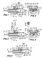
- Figures 1, 2 and 5 show how the actuating shaft 16 is formed with the radial actuating extension 22, the size of which snugly corresponds to that of the transverse positioning notch 20 of the retaining spring member 15.
- the said radial actuating extension 22 may actuate the retaining spring member is by pressing against it.
Landscapes
- Engineering & Computer Science (AREA)
- General Engineering & Computer Science (AREA)
- Health & Medical Sciences (AREA)
- Oral & Maxillofacial Surgery (AREA)
- Mechanical Engineering (AREA)
- Flexible Shafts (AREA)
- Details Of Connecting Devices For Male And Female Coupling (AREA)
- Laying Of Electric Cables Or Lines Outside (AREA)
- Automotive Seat Belt Assembly (AREA)
- Mechanical Control Devices (AREA)
Claims (3)
- Längenselbsteinstellungseinrichtung für Steuerkabel, ausgebildet durch: ein Hauptkörperelement (CP), das gut passend mechanische Rückhaltemittel (MR) für einen da hindurchgehenden Einstellungsstift bzw. -ansatz (VR) aufnimmt und welches mit Mitteln (2, 3) versehen ist, die es ermöglichen, an einer fixen bzw. bestimmten Stelle der Kraftfahrzeugskonstruktion verankert zu werden; die Rückhaltemittel (MR) weisen ein kerbenartiges Element (17) auf, das mit Rückhaltemitteln (18) versehen ist, wobei der Einstellungsansatz bzw. -stift (VR) extern mit einem rückhaltenden Schraubengang (9) ausgebildet ist, der angemessen relativ zu Zug- bzw. Dehnungsbeanspruchungen, die darauf einwirken, bemessen ist, und an dessen einem Ende das entsprechende Ende (E) eines Mantels (12) eines Stahlkabels (13) gut zusammenpassend aufnimmt, an welchem es dauerhaft angesetzt ist, wobei das Stahlkabel (13) ohne Mantel zweckmäßig in der Längsrichtung durch den Einstellungsansatz bzw. -stift (VR) zu gleiten in der Lage ist und an dem Ende einen umfänglichen Flansch (11) hat, gegen welchen eine Steuerungsfeder (RR) drückt; die Steuerungsfeder (RR), die koaxial um den Einstellungsansatz bzw. -stift (VR) angeordnet ist und dauernd gegen den umfänglichen Flansch (11) des Einstellungsansatzes bzw. -stifts (VR) drückt; das Hauptkörperelement (CP), das eine zentral angeordnete Erstreckung (2) aufweist, die sich auswärts über einen ausreichenden Abstand erstreckt und deren Abmessungen und äußere Konstruktion es ermöglichen, das Hauptkörperelement (CP) an einer bestimmten bzw. fixen Stelle der Kraftfahrzeugstruktur zu verankern, wobei die Erstreckung (2) und das Hauptkörperelement (CP) vollständig durch ein in Längsrichtung erstrecktes Durchgangsloch (4) durchzogen sind, durch das der Einstellungsstift bzw. -ansatz (VR) gut passend gleiten kann, wobei das Durchgangsloch (4) eine Einlaßöffnung hat und innerhalb des Hauptkörperelements (CP) eine längserstreckte Ausnehmung (5) definiert, die zweckmäßig als ein Sitz für den Einstellungsstift bzw. -ansatz (VR) abgemessen ist und einer zentral angeordneten oberen Öffnung (6) gegenüberliegt;
gekennzeichnet durch die folgenden Merkmale:a) ein zentrales Teil des Hauptkörperelements (CP) ist als ein im wesentlichen rechtwinkliger und hohler kasten-bzw. büchsenartiger Körper (CP) ausgebildet;b) die Erstreckung (2) ist an einer ersten Hauptoberfläche des Körpers (CP) ausgebildet;c) an einer zweiten Hauptoberfläche, die der ersten gegenüberliegt, ist die Einlaßöffnung des in Längsrichtung erstreckten Durchgangslochs (4) angeordnet; undd) an einer dritten und einer vierten Seitenoberfläche des Körpers (CP), die passend relativ zu dem Durchgangsloch (4) mit entsprechend gegenüberliegenden Öffnungen (7) von im wesentlichen viereckigem bzw. vierseitigem Umfang, sind die jeweiligen oberen Seiten der Öffnungen durch jeweilige kanalartige Kerbungen durchquert;e) wobei die Rückhaltemittel (MR) eine hebelartige Verlängerung (23) und eine Betätigungserstreckung (22) aufweisen, um auf das kerbenartige Element (17) einzuwirken, um es in Richtung des zurückhaltenden Schraubengewindes (9) zu bewegen. - Längenselbsteinstellungsvorrichtung für Steuerkabel nach Anspruch 1, dadurch gekennzeichnet, daß die Rückhaltemittel (MR) für den Einstellungsstift bzw. -ansatz (VR) gebildet sind durch:a) Betätigungsmittel (16, 21, 22, 23, 24 und 25); undb) ein im wesentlichen rechts parallelepipedisches Rückhaltefederelement (15), das passend abgemessen ist, um innerhalb des Hauptkörperelements (CP) gut passend zu gleiten und welches an einer seiner in Längsrichtung erstreckten Hauptoberflächen mit einer zentral angeordneten transversalen Kerbung (17) ausgebildet ist, die einen gebogenen bzw. gekrümmten Umfang hat, der mit einem Rückhaltegewinde (18) versehen ist, das abgemessen ist, um zu dem Rückhaltegewinde (9) zu passen, das an dem Einstellstift bzw. -ansatz (VR) ausgebildet ist, und zwei passend abgemessene Vorsprünge bzw. Grate (19) aufweist, die tangential winklig zu der querverlaufenden Kerbe (17) angeordnet sind, und die dauernd gegen das Hauptkörperelement (CP) drücken können, und auf der gegenüberliegenden Oberfläche zu der vorherigen eine querverlaufende Positionierungskerbe (20).
- Längenselbsteinstellungsvorrichtung für Steuerkabel nach Anspruch 1 und 2, dadurch gekennzeichnet, daß die Betätigungsmittel ausgebildet sind durch:a) eine Betätigungswelle (16), die gut passend in dem Hauptkörperelement (CP) querverlaufend zu der Achse der darauf ausgebildeten zentral angeordneten Erstreckung (2) und übereinandergelegt auf dem rückhaltenden Federelement (15) angeordnet ist, und die an ihren beiden Enden mit entsprechenden umfänglichen Flanschen (21) ausgebildet ist, die als Mitnehmer bzw. Klauen wirken, um zu verhindern, daß sie aus dem Hauptkörperelement (CP) kommen kann, und eine in dem Abschnitt, der durch die Breite der querverlaufenden Positionierungskerbe (20) ausgebildet ist, die in dem Federrückhalteelement ausgebildet ist, eine radiale Betätigungserstreckung (22), die auf das Federrückhalteelement (15) zu wirken vermag, so daß eine Drehung der Betätigungswelle (16) in einer ausreichenden Entfernung in Längsrichtung relativ zu der Achse, die durch den Einstellungsstift bzw. -ansatz (VR) bestimmt ist, in einer Richtung bewirkt, wobei das Federrückhalteelement (15) dichter an den Einstellungsstift bzw. -ansatz (VR) bewegt wird, wobei der letztere in einer Stellung unter der kombinierten Wirkung der darauf ausgebildeten Rückhaltegewinde (9, 18) festgehalten wird, während die Drehung der Betätigungswelle (16) in der entgegengesetzten Richtung bewirkt, daß das Federrückhalteelement (15) von dem Einstellungsstift bzw. -ansatz (VR) wegbewegt wird, wodurch es aus der kombinierten Wirkung der darauf ausgebildeten Rückhaltegewinde (9, 18) entlassen wird;b) eine gebogene Verlängerung bzw. ein gebogener Fortsatz (23), die bzw. der sich von der Betätigungswelle (16) zur Vereinfachung der Betätigung der Welle erstreckt; undc) eine Positionierungsschulter bzw. -ansatz (25), die bzw. der äußerlich an dem Hauptkörperelement (CP) in funktionaler Entsprechung zu der gebogenen Verlängerung bzw. dem gebogenen Fortsatz (23) ausgebildet ist, die sich von der Betätigungswelle (16) erstreckt, wobei die Positionierungsschulter bzw. -ansatz (25) angepaßt ist, um die Stellung der gebogenen Verlängerung bzw. des gebogenen Ansatzes (23), in welcher bzw. welchem die Stellung des Einstellstiftes bzw. -ansatzes (VR) festgesetzt ist, einzustellen.
Applications Claiming Priority (3)
| Application Number | Priority Date | Filing Date | Title |
|---|---|---|---|
| ES9001506 | 1990-05-31 | ||
| ES9001506A ES2024819A6 (es) | 1990-05-31 | 1990-05-31 | Mecanismo autoajustador de la longitud de cables de mando. |
| PCT/ES1991/000020 WO1991019110A1 (es) | 1990-05-31 | 1991-04-09 | Mecanismo autoajustador de la longitud de cables de mando |
Publications (2)
| Publication Number | Publication Date |
|---|---|
| EP0485541A1 EP0485541A1 (de) | 1992-05-20 |
| EP0485541B1 true EP0485541B1 (de) | 1996-03-13 |
Family
ID=8267541
Family Applications (1)
| Application Number | Title | Priority Date | Filing Date |
|---|---|---|---|
| EP91907483A Expired - Lifetime EP0485541B1 (de) | 1990-05-31 | 1991-04-09 | Steuerseilselbsteinstellmechanismus |
Country Status (8)
| Country | Link |
|---|---|
| US (1) | US5259265A (de) |
| EP (1) | EP0485541B1 (de) |
| JP (1) | JPH05501910A (de) |
| AT (1) | ATE135446T1 (de) |
| AU (1) | AU7670291A (de) |
| DE (1) | DE69117882T2 (de) |
| ES (1) | ES2024819A6 (de) |
| WO (1) | WO1991019110A1 (de) |
Cited By (2)
| Publication number | Priority date | Publication date | Assignee | Title |
|---|---|---|---|---|
| DE10127630C2 (de) * | 2000-06-13 | 2003-04-30 | Kuester Automotive Control Sys | Vorrichtung zur Längeneinstellung, insbesondere einer Fernbetätigung in Kraftfahrzeugen |
| DE102014007161A1 (de) * | 2014-05-15 | 2015-11-19 | GM Global Technology Operations LLC (n. d. Gesetzen des Staates Delaware) | Längseinsteller |
Families Citing this family (14)
| Publication number | Priority date | Publication date | Assignee | Title |
|---|---|---|---|---|
| US5142933A (en) * | 1991-05-23 | 1992-09-01 | Teleflex Incorporated | Motion transmitting remote control assembly having conduit length adjuster |
| GB2265956B (en) * | 1992-04-06 | 1995-09-27 | Nhk Spring Co Ltd | An adjustable mounting for a control cable |
| DE4321985C1 (de) * | 1993-07-01 | 1995-01-12 | Ameu Management Corp | Verstellvorrichtung in einem Sitz für eine in einer mit dem Sitz verbindbaren Lehne angeordnete Becken- und/oder Lordosenstütze mit einer sie verbindenden Bowdenzuganordnung |
| ES2117927B1 (es) * | 1995-02-20 | 1999-04-01 | Fico Cables Sa | Dispositivo autoajustador de cables de mando. |
| ES2128233B1 (es) * | 1996-03-15 | 2000-02-01 | Fico Cables Sa | Dispositivo autoajustador para terminales de cables de mando. |
| US5842552A (en) * | 1996-12-26 | 1998-12-01 | White Consolidated Industries, Inc. | Self-adjusting drive-control cable for a lawn mower |
| FR2767566B1 (fr) * | 1997-08-19 | 1999-11-26 | Peugeot | Agencement de commande, a cable sous gaine, notamment pour actionner un embrayage a friction de vehicule automobile |
| US6053064A (en) * | 1998-05-01 | 2000-04-25 | L & P Property Management Company | Lumbar support screw actuator |
| DE10055425C2 (de) * | 2000-11-09 | 2002-11-21 | Faurecia Autositze Gmbh & Co | Vorrichtung zum Längenausgleich an Bowdenzügen |
| WO2007056650A2 (en) * | 2005-11-02 | 2007-05-18 | L & P Property Management Company | Hinged slide and snap cable end fitting |
| DE202008016381U1 (de) | 2008-12-11 | 2010-04-29 | Al-Ko Kober Ag | Seilzugeinstellung |
| US8690109B2 (en) | 2011-08-03 | 2014-04-08 | Haworth, Inc. | Automatic gap adjustor |
| US8850921B2 (en) | 2011-12-12 | 2014-10-07 | Chrysler Group Llc | Cable-length-adjustment device |
| DE102012201709B4 (de) * | 2012-02-06 | 2015-06-25 | Johnson Controls Gmbh | Vorrichtung zur Umkehr der Bewegungs- und/oder Betätigungsrichtung eines Betätigungszuges eines Mechanismus |
Family Cites Families (15)
| Publication number | Priority date | Publication date | Assignee | Title |
|---|---|---|---|---|
| US3572159A (en) * | 1969-06-12 | 1971-03-23 | Teleflex Inc | Motion transmitting remote control assembly |
| GB1366325A (en) * | 1970-10-08 | 1974-09-11 | Teleflex Inc | Remote control assembly |
| US3710645A (en) * | 1970-10-08 | 1973-01-16 | Teleflex Inc | Remote control assembly |
| US4294133A (en) * | 1979-09-24 | 1981-10-13 | Ford Motor Company | Bowden cable retainer and adjuster |
| US4669330A (en) * | 1984-10-01 | 1987-06-02 | Ford Motor Company | Cable length adjuster |
| US4676119A (en) * | 1985-09-13 | 1987-06-30 | Teleflex Incorporated | Remote control levered self adjust actuator |
| US4841806A (en) * | 1985-09-13 | 1989-06-27 | Teleflex Incorporated | Self-adjust mini increment |
| US4694706A (en) * | 1986-02-14 | 1987-09-22 | Acco Babcock Inc. | Control cable conduit length adjustment device |
| JPS62209210A (ja) * | 1986-03-07 | 1987-09-14 | Nippon Cable Syst Inc | 操作用ワイヤの張力調節装置 |
| US4688445A (en) * | 1986-04-21 | 1987-08-25 | Teleflex Incorporated | Remote control balanced adjust system |
| GB2195161A (en) * | 1986-09-12 | 1988-03-30 | Ford Motor Co | Cable clip |
| US4872367A (en) * | 1988-06-17 | 1989-10-10 | Teleflex Incorporated | Lost motion end fitting |
| JPH0262415A (ja) * | 1988-08-24 | 1990-03-02 | Nippon Cable Syst Inc | コントロールケーブルの取付位置調整装置 |
| US4854185A (en) * | 1988-10-17 | 1989-08-08 | Babcock Industries Inc. | Manually operated and locked conduit length adjuster system |
| ES2024240A6 (es) * | 1990-05-07 | 1992-02-16 | Pujol & Tarago | Dispositivo autoajustador de la longitud de cables de mando. |
-
1990
- 1990-05-31 ES ES9001506A patent/ES2024819A6/es not_active Expired - Lifetime
-
1991
- 1991-04-09 AT AT91907483T patent/ATE135446T1/de not_active IP Right Cessation
- 1991-04-09 US US07/828,928 patent/US5259265A/en not_active Expired - Fee Related
- 1991-04-09 AU AU76702/91A patent/AU7670291A/en not_active Abandoned
- 1991-04-09 DE DE69117882T patent/DE69117882T2/de not_active Expired - Fee Related
- 1991-04-09 WO PCT/ES1991/000020 patent/WO1991019110A1/es not_active Ceased
- 1991-04-09 JP JP3506894A patent/JPH05501910A/ja active Pending
- 1991-04-09 EP EP91907483A patent/EP0485541B1/de not_active Expired - Lifetime
Cited By (2)
| Publication number | Priority date | Publication date | Assignee | Title |
|---|---|---|---|---|
| DE10127630C2 (de) * | 2000-06-13 | 2003-04-30 | Kuester Automotive Control Sys | Vorrichtung zur Längeneinstellung, insbesondere einer Fernbetätigung in Kraftfahrzeugen |
| DE102014007161A1 (de) * | 2014-05-15 | 2015-11-19 | GM Global Technology Operations LLC (n. d. Gesetzen des Staates Delaware) | Längseinsteller |
Also Published As
| Publication number | Publication date |
|---|---|
| DE69117882D1 (de) | 1996-04-18 |
| DE69117882T2 (de) | 1996-07-25 |
| AU7670291A (en) | 1991-12-31 |
| JPH05501910A (ja) | 1993-04-08 |
| ES2024819A6 (es) | 1992-03-01 |
| US5259265A (en) | 1993-11-09 |
| EP0485541A1 (de) | 1992-05-20 |
| ATE135446T1 (de) | 1996-03-15 |
| WO1991019110A1 (es) | 1991-12-12 |
Similar Documents
| Publication | Publication Date | Title |
|---|---|---|
| EP0485541B1 (de) | Steuerseilselbsteinstellmechanismus | |
| EP0431307B1 (de) | Einstellbares Kabelhüllenendstück | |
| US4378713A (en) | Self-adjusting cable control device | |
| EP0365242B1 (de) | Handgesteuerte verriegelbare Längenverstellvorrichtung | |
| US4344518A (en) | Self-adjusting cable conduit mechanism | |
| EP0699841B1 (de) | Steueranlage mit Bowdenzug | |
| US5235867A (en) | Lockout means for cable tension adjustment | |
| EP0485540B1 (de) | Steuerseilselbsteinstellvorrichtung | |
| US5163338A (en) | Cable core length adjuster mechanism | |
| EP0653028A1 (de) | Drehbare temperatureinstellvorrichtung | |
| EP0619437A1 (de) | Selbsteinstellende vorrichtung für die länge von steuerkabeln | |
| US5142933A (en) | Motion transmitting remote control assembly having conduit length adjuster | |
| WO1998019900A1 (en) | Parking brake mechanism and methods of assembly and operation | |
| JPS63195034A (ja) | コントロ−ルケ−ブルの取付装置 | |
| US4261221A (en) | Control cable positioning device | |
| US4292858A (en) | Brake cable operating means of the overcenter toggle type | |
| EP0260980A2 (de) | Selbstnachstellende Seilbetätigungsvorrichtung mit Instandhaltung der Spannung | |
| US5364168A (en) | Retractor shaft-rotating type seat belt pretensioner | |
| US4549709A (en) | Device for attaching to a wall the end of a sheath in which a control cable is slidably received | |
| EP0085566B1 (de) | Haspel zum Positionieren | |
| EP1568539A1 (de) | Betätigungsmechanismus für Bowdenzüge | |
| GB2047519A (en) | Mounting device | |
| EP0690199B1 (de) | Seilklemme | |
| US6244129B1 (en) | Regulator for automatically adjusting the length of an actuating link | |
| ES8606592A1 (es) | Perfeccionamientos en un motor de freno con reglaje automa- tico |
Legal Events
| Date | Code | Title | Description |
|---|---|---|---|
| PUAI | Public reference made under article 153(3) epc to a published international application that has entered the european phase |
Free format text: ORIGINAL CODE: 0009012 |
|
| 17P | Request for examination filed |
Effective date: 19920121 |
|
| AK | Designated contracting states |
Kind code of ref document: A1 Designated state(s): AT BE DE FR GB IT NL SE |
|
| 17Q | First examination report despatched |
Effective date: 19930701 |
|
| RAP1 | Party data changed (applicant data changed or rights of an application transferred) |
Owner name: FICO-CABLES, S.A. |
|
| GRAH | Despatch of communication of intention to grant a patent |
Free format text: ORIGINAL CODE: EPIDOS IGRA |
|
| GRAA | (expected) grant |
Free format text: ORIGINAL CODE: 0009210 |
|
| AK | Designated contracting states |
Kind code of ref document: B1 Designated state(s): AT BE DE FR GB IT NL SE |
|
| PG25 | Lapsed in a contracting state [announced via postgrant information from national office to epo] |
Ref country code: NL Free format text: LAPSE BECAUSE OF FAILURE TO SUBMIT A TRANSLATION OF THE DESCRIPTION OR TO PAY THE FEE WITHIN THE PRESCRIBED TIME-LIMIT Effective date: 19960313 Ref country code: BE Effective date: 19960313 Ref country code: AT Effective date: 19960313 |
|
| REF | Corresponds to: |
Ref document number: 135446 Country of ref document: AT Date of ref document: 19960315 Kind code of ref document: T |
|
| REF | Corresponds to: |
Ref document number: 69117882 Country of ref document: DE Date of ref document: 19960418 |
|
| ET | Fr: translation filed | ||
| ITF | It: translation for a ep patent filed | ||
| PG25 | Lapsed in a contracting state [announced via postgrant information from national office to epo] |
Ref country code: SE Effective date: 19960613 |
|
| NLV1 | Nl: lapsed or annulled due to failure to fulfill the requirements of art. 29p and 29m of the patents act | ||
| PLBE | No opposition filed within time limit |
Free format text: ORIGINAL CODE: 0009261 |
|
| STAA | Information on the status of an ep patent application or granted ep patent |
Free format text: STATUS: NO OPPOSITION FILED WITHIN TIME LIMIT |
|
| 26N | No opposition filed | ||
| REG | Reference to a national code |
Ref country code: GB Ref legal event code: IF02 |
|
| PGFP | Annual fee paid to national office [announced via postgrant information from national office to epo] |
Ref country code: GB Payment date: 20040206 Year of fee payment: 14 |
|
| PGFP | Annual fee paid to national office [announced via postgrant information from national office to epo] |
Ref country code: FR Payment date: 20040210 Year of fee payment: 14 |
|
| PGFP | Annual fee paid to national office [announced via postgrant information from national office to epo] |
Ref country code: DE Payment date: 20040528 Year of fee payment: 14 |
|
| PG25 | Lapsed in a contracting state [announced via postgrant information from national office to epo] |
Ref country code: IT Free format text: LAPSE BECAUSE OF NON-PAYMENT OF DUE FEES;WARNING: LAPSES OF ITALIAN PATENTS WITH EFFECTIVE DATE BEFORE 2007 MAY HAVE OCCURRED AT ANY TIME BEFORE 2007. THE CORRECT EFFECTIVE DATE MAY BE DIFFERENT FROM THE ONE RECORDED. Effective date: 20050409 Ref country code: GB Free format text: LAPSE BECAUSE OF NON-PAYMENT OF DUE FEES Effective date: 20050409 |
|
| PG25 | Lapsed in a contracting state [announced via postgrant information from national office to epo] |
Ref country code: DE Free format text: LAPSE BECAUSE OF NON-PAYMENT OF DUE FEES Effective date: 20051101 |
|
| GBPC | Gb: european patent ceased through non-payment of renewal fee |
Effective date: 20050409 |
|
| PG25 | Lapsed in a contracting state [announced via postgrant information from national office to epo] |
Ref country code: FR Free format text: LAPSE BECAUSE OF NON-PAYMENT OF DUE FEES Effective date: 20051230 |
|
| REG | Reference to a national code |
Ref country code: FR Ref legal event code: ST Effective date: 20051230 |