EP0485618A1 - Procede de determination de l'acceptabilite de produits pour presse d'injection - Google Patents
Procede de determination de l'acceptabilite de produits pour presse d'injection Download PDFInfo
- Publication number
- EP0485618A1 EP0485618A1 EP91909710A EP91909710A EP0485618A1 EP 0485618 A1 EP0485618 A1 EP 0485618A1 EP 91909710 A EP91909710 A EP 91909710A EP 91909710 A EP91909710 A EP 91909710A EP 0485618 A1 EP0485618 A1 EP 0485618A1
- Authority
- EP
- European Patent Office
- Prior art keywords
- molding machine
- injection molding
- product acceptance
- rejection
- products
- Prior art date
- Legal status (The legal status is an assumption and is not a legal conclusion. Google has not performed a legal analysis and makes no representation as to the accuracy of the status listed.)
- Granted
Links
Images

Classifications
-
- B—PERFORMING OPERATIONS; TRANSPORTING
- B29—WORKING OF PLASTICS; WORKING OF SUBSTANCES IN A PLASTIC STATE IN GENERAL
- B29C—SHAPING OR JOINING OF PLASTICS; SHAPING OF MATERIAL IN A PLASTIC STATE, NOT OTHERWISE PROVIDED FOR; AFTER-TREATMENT OF THE SHAPED PRODUCTS, e.g. REPAIRING
- B29C45/00—Injection moulding, i.e. forcing the required volume of moulding material through a nozzle into a closed mould; Apparatus therefor
- B29C45/17—Component parts, details or accessories; Auxiliary operations
- B29C45/76—Measuring, controlling or regulating
- B29C45/768—Detecting defective moulding conditions
Definitions
- the present invention relates to a product acceptance/rejection judgment method for an injection molding machine, and more particularly, to a product acceptance/rejection judgment method which makes it possible to accurately determine whether a product is acceptable or not at all times even when an injection molding machine is operated in various operating environments.
- the conventional method does not adequately take into account operating environment changes involved in determining whether a product is acceptable or not. If the operating environments of an injection molding machine change, corresponding molding process parameter values change accordingly, therefore, the operating environment changes are indirectly considered in the conventional acceptance/rejection judgment. For instance, if a window of a factory which is usually closed is opened to let wind blow onto a die installed on an injection molding machine, causing the die to be cooled, then the injection time increases. And if the injection time exceeds its tolerance limit, then the product molded at that time is determined to be defective. However, it takes time for a molding process parameter value to deviate from its tolerance limit after a defective unit results from an operating environment change. During that time, therefore, accurate product acceptance/rejection judgment cannot be implemented, causing the occurrence of defective units.
- An object of the present invention is to provide a product acceptance/rejection judgment method which makes it possible to always make accurate judgment whether a unit is defective or not even when an injection molding machine is operated in different operating environments.
- the values of operating parameters which directly indicate the injection molding machine operating environments involved in judging the quality of a product are detected, and if the detected operating parameter values deviate from tolerance limits, then it is judged that a molding failure has taken place.
- the present invention it is judged that a molding failure has occurred if the detected values of the operating parameters which directly indicate the injection molding machine operating environments involved in judging the quality of products deviate from tolerance limits, therefore, if any operating environment change that can lead to a molding failure takes place, then it is immediately determined that a molding failure has occurred. Consequently, even when an injection molding machine is operated in diverse operating environments, accurate product acceptance/rejection judgment can be always performed, helping carry out good quality control of moldings.
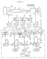
- the injection molding machine for carrying out the product acceptance/rejection judgment method according to the embodiment of the present invention is provided with various mechanism such as an injection mechanism, clamping mechanism, and ejector.
- the injection mechanism is equipped with a screw 1 installed in a heating cylinder 4, an injection servomotor 2 for driving the screw in the axial direction, and a servomotor (not shown) for rotating the screw 1, and it is designed to inject a molding material (resin) which has been plasticized and kneaded in the heating cylinder 4 into a molding cavity 5a formed in a die 5 by moving the screw 1 in the axial direction.
- a molding material resin
- a pulse coder 3 for detecting a motor rotational position (a position on the screw axis) is installed on the injection servomotor 2, and a pressure sensor 6 which comprises, for example, a load cell, for detecting a resin pressure (an axial reaction force of molten resin applied to the screw) is mounted on the screw 1. Also, a die temperature sensor 8 for detecting the die surface temperature is mounted on the external surface of the die 5. Further, the injection molding machine has an open air temperature sensor 9 for detecting the temperature of the surrounding air and a wind velocity sensor 10 for detecting the velocity of the wind around the injection molding machine.
- a reference numeral 14 denotes a humidity sensor which is mounted on the injection molding machine as necessary to detect the humidity around the injection molding machine.
- a reference numeral 20 denotes a numerically controlled device (NC device) 20 for driving and controlling the diverse mechanisms of the injection molding machine.
- the NC device 20 is equipped with a microprocessor 21 for numerical control (CPU for NC) and a microprocessor 22 for a programmable machine controller (CPU for PMC) to provide a numerical control function and a sequence control function.
- CPU for NC numerical control
- PMC programmable machine controller
- a read-only memory (ROM) 24 which stores a control program for controlling an entire injection molding machine
- a random-access memory (RAM) 25 which is used for temporarily storing data or the like
- a servo circuit (only the servo circuit related to the injection motor 2 is indicated at 27) for driving and controlling the servomotors of the individual axes via a servo interface 26.
- the servo circuit 27 is connected to the injection motor 2 and the pulse coder 3.
- a ROM 28 wherein a sequence program or the like for controlling the sequential operation of the injection molding machine is stored
- a RAM 29 which is connected to a pressure sensor 6 via an A-D converter 7 and which stores pressure data that is received from the A-D converter 7 and that corresponds to a resin pressure detected by the pressure sensor 6, and a RAM 30 used for temporarily storing data such as a calculation result given by the PMC CPU 22.
- the NC device 20 is further equipped with a bus arbiter controller (BAC) 23 for bus control.
- BAC bus arbiter controller
- To the BAC 23 are connected buses 36 of the CPUs 21 and 22, a shared memory 31, an input circuit 32, and an output circuit 33.
- the shared memory 31 stores an NC program, molding conditions, setting values, etc., and comprises a nonvolatile RAM.
- To each of the input circuit 32 and the output circuit 33 are connected diverse sensors and actuators (none of them are shown) installed in the diverse mechanisms of the injection molding machine, including the die temperature sensor 8, the open air temperature sensor 9, and a wind velocity sensor 10, and a corresponding servo circuit 27.
- the sensors 8, 9 and 10 are connected to the input circuit 32 via the A-D converters 11, 12 and 13 for converting analog sensor outputs to digital signals.
- a reference numeral 15 indicates an A-D converter matched to the humidity sensor 14, and a reference numeral 35 denotes a manual data input device with a CRT display unit (CRT/MDI) connected
- auxiliary product acceptance/rejection judgment based on at least one operating parameter die surface temperature, the open air temperature and wind velocity around the injection molding machine, etc.
- at least one operating parameter die surface temperature, the open air temperature and wind velocity around the injection molding machine, etc.
- various molding process parameters cushion amount, injection time, metering time, metering completion position, injection pressure peak value, screw position where the injection speed control mode is switched to the injection pressure control, etc.
- the tolerance limits (upper and lower limit values) of the individual operating parameters indicating the operating environments that ensure molding of non-defective units are predetermined by carrying out experiments or the like before starting mass production of moldings, and these values and flag information that indicates the type of an operating parameter to be used for the auxiliary product acceptance/rejection judgment are manually set in the NC device 20.
- the CRT/MDI 35 is equipped with a CRT screen (not illustrated) for displaying parameter setting information used to set the type of operating parameter for making the auxiliary product acceptance/rejection judgment and to set the upper and lower limit values of the operating parameters, and a keyboard having operating keys for manually entering alphanumeric strings for setting the upper and lower limit values of the operating parameters and the flag information.
- the shared RAM 31 has a memory area for storing the upper and lower limit values of the operating parameters and the flag information.
- symbols TOH and TOL denote the upper and lower limit values of the open air temperature
- TDH and TDL the upper and lower limit values of the die surface temperature
- WVH and WVL the upper and lower limit values of the wind velocity.
- symbols FO, FD and FV represent the flags for the open air temperature, die surface temperature and wind velocity, respectively.
- an operator depresses the key for selecting the parameter setting screen of the CRT/MDI 35.
- the parameter setting screen (not illustrated) is shown on the CRT screen under the control of the PMC CPU 22.
- the operator normally enters by hand successively, through the keyboard of the CRT/MDI 35, at least one type of operating parameter and the upper and lower limit values of at least one operating parameter related to one particular type of product, referring to the setting screen.
- the PMC CPU 22 stores the manually entered upper and lower limit values of the operating parameter in the shared RAM 31, and sets the value of a corresponding flag memory of the shared RAM 31 to "1.” As necessary, the same operation is repeated according to the same procedure for another type of molding.
- the NC device 20 controls the injection molding machine as conventionally known in accordance with the NC program stored in the shared RAM 31, the sequence program stored in the ROM 28, and the molding conditions preset in the shared RAM 31. More specifically, the servo circuit 27 receives a distributing pulse from the NC CPU 21 via the servo interface 26 and also receives a feedback pulse from the pulse coder 3, determines a speed command by D/A-converting a deviation of an actual position of the injection motor 2 from a command position, and determines the actual speed by F/V-converting an output of the pulse coder.
- the servo circuit 27 supplies a driving current to the injection motor 2 according to a result of the comparison between the speed command and the actual speed and a torque limit value supplied by the PMC CPU 22 via the output circuit 33, thereby controlling the output torque of the injection motor.
- the foregoing injection speed control mode is switched to the conventional well-known injection pressure control mode.
- the mechanisms other than the injection mechanism are controlled in a well-known mode, and in this way, the conventional well-known molding cycle is repeatedly implemented.
- the PMC CPU 22 sequentially executes a series of processes of clamping, injecting, holding, making product acceptance/rejection judgment, metering, die opening, and ejecting (steps S1 through S7 in FIG. 2).
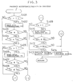
- the PMC CPU 22 first determines whether or not the flag F0 is "1" which indicates that the auxiliary product acceptance/rejection judgment based on the open air temperature should be performed (step S401). If the judgment results in the step S401 is negative, then the CPU 22 determines whether or not the flag FD is "1" which indicates that the auxiliary product acceptance/rejection judgment based on the die surface temperature should be performed (step S405). If the judgment result of the step S405 is negative, then the CPU 22 further determines whether or not the flag FW is "1" which indicates that the auxiliary product acceptance/rejection judgment based on the wind velocity should be performed (step S409).
- the CPU 22 executes the normal product acceptance/rejection judgment process in a step S413.
- the normal product acceptance/rejection judgment process it is determined whether or not the detected values of various molding process parameters (cushion amount, injection time, metering time, metering completion point, injection pressure peak value, screw position where the injection speed control mode is switched to the injection pressure control mode, etc.) are within the tolerance limits.
- a chute which is provided midway on a product carrying path (not shown) located, for example, at the bottom of the ejector, and which separates non-defectives from defectives, is switched to the non-defectives carrying path side under the control of the NC device 20. In this way, the product obtained from that molding cycle is carried to a non-defectives storing space.
- the CPU 22 issues a failure signal.
- the chute In response to the failure signal, the chute is switched to the defectives carrying path side under the control of the NC device 20 to carry the product to a defectives storing space. Then, the CPU 22 begins the metering process (a step S5 of FIG. 2) for the subsequent product.
- the PMC CPU 22 reads, via the input circuit 32 and the BAC 23, the output data from the A-D converter 12 which data corresponds to an analog output of the open air temperature sensor 9 and indicates the actual open air temperature T0 (step 402), and determines whether the open air temperature T0 exceeds the lower limit value T0L or not in order to perform the auxiliary product acceptance/rejection judgment based on the open air temperature for this molding cycle (step S403). If the judgment result in the step S403 is positive, then the CPU 22 determines whether the open air temperature T0 is below the upper limit value T0H or not (step S404).
- step S403 or S404 If the judgment result of the step S403 or S404 is negative, which means that the open air temperature deviates from the tolerance limits, there is a possibility of a molding failure having occurred, therefore, a failure signal is sent out (step S414), and the process of FIG. 3 for that molding cycle is terminated.
- the failure signal is issued, the product obtained from the molding cycle is carried to the defectives storing space as in the case where the failure signal is generated in the normal product acceptance/rejection judgment process.
- step S403 determines whether the open air temperature is within the tolerance limits. If the judgment result of the step S405 is negative, then the program goes to the foregoing step S409.
- step S405 If the judgment result of the step S405 is positive, then the CPU 22 reads, via the input circuit 32 and the BAC 23, the output data from the A-D converter 11 which data corresponds to an analog output of the die temperature sensor 8 and indicates the actual die surface temperature TD (step S406), and determines whether the die surface temperature TD exceeds the lower limit value TDL or not (step S407) in order to perform the auxiliary product acceptance/rejection judgment based on the die surface temperature. If the judgment result in the step S407 is positive, then the CPU 22 determines whether the die surface temperature TD is below the upper limit value TDH or not (step S408).
- step S407 or S408 If the judgment result of the step S407 or S408 is negative, which means that the die surface temperature deviates from the tolerance limits, there is a possibility of a molding failure having occurred, and therefore, a failure signal is sent out (step S414), then the process of FIG. 3 for the molding cycle is terminated.
- step S407 and S408 are positive, which means that the die surface temperature is within the tolerance limits, then the CPU 22 determines whether the value of the flag FW is "1" or not (step S409). If the judgment result of the step S409 is negative, then the program goes to the foregoing step S413.
- step S409 If the judgment result of the step S409 is positive, then the CPU 22 reads, via the input circuit 32 and the BAC 23, the output data from the A-D converter 13 which data corresponds to an analog output of the wind velocity sensor 10 and indicates the actual wind velocity WV (step S410), and determines whether the wind velocity WV is higher than the lower limit value WVL or not in order to perform the auxiliary product acceptance/rejection judgment based on the wind velocity (step S411). If the judgment result in the step S411 is positive, then the CPU 22 determines whether the wind velocity WV is below the upper limit value WVH or not (step S412).
- step S411 or S412 If the judgment result of the step S411 or S412 is negative, which means that the wind velocity deviates from the tolerance limits, there is a possibility of a molding failure having occurred, and therefore, a failure signal is sent out (step S414), then the process of FIG. 3 for the molding cycle is terminated.
- step S411 and S412 If both judgment results of the steps S411 and S412 are positive, which means that the wind velocity is within the tolerance limits, then it is determined that all the open air temperature, die surface temperature, and the wind velocity are within the tolerance limits.
- the normal product acceptance/rejection judgment process is carried out (step S413). Then, in accordance with the normal product acceptance/rejection judgment result, the product produced from that molding cycle is carried to the non-defectives storing space or the defectives storing space as described above.
- the present invention is not limited to the foregoing embodiment but is available in diverse variations. For instance, if the injection molding machine is operated in an operating environment where humidity can significantly change, an auxiliary product acceptance/rejection judgment process based on the humidity around the injection molding machine which process is similar to those described above may be carried out, using a humidity sensor 14 and an A-D converter 15 shown with broken lines in FIG. 1.
Landscapes
- Engineering & Computer Science (AREA)
- Manufacturing & Machinery (AREA)
- Mechanical Engineering (AREA)
- Injection Moulding Of Plastics Or The Like (AREA)
Abstract
Applications Claiming Priority (3)
| Application Number | Priority Date | Filing Date | Title |
|---|---|---|---|
| JP2141607A JP2767313B2 (ja) | 1990-06-01 | 1990-06-01 | 射出成形機 |
| JP141607/90 | 1990-06-01 | ||
| PCT/JP1991/000715 WO1991018729A1 (fr) | 1990-06-01 | 1991-05-28 | Procede de determination de l'acceptabilite de produits pour presse d'injection |
Publications (3)
| Publication Number | Publication Date |
|---|---|
| EP0485618A1 true EP0485618A1 (fr) | 1992-05-20 |
| EP0485618A4 EP0485618A4 (en) | 1992-07-08 |
| EP0485618B1 EP0485618B1 (fr) | 1997-01-29 |
Family
ID=15295950
Family Applications (1)
| Application Number | Title | Priority Date | Filing Date |
|---|---|---|---|
| EP91909710A Expired - Lifetime EP0485618B1 (fr) | 1990-06-01 | 1991-05-28 | Procede de determination de l'acceptabilite de produits pour presse d'injection |
Country Status (5)
| Country | Link |
|---|---|
| US (1) | US5283018A (fr) |
| EP (1) | EP0485618B1 (fr) |
| JP (1) | JP2767313B2 (fr) |
| DE (1) | DE69124464T2 (fr) |
| WO (1) | WO1991018729A1 (fr) |
Families Citing this family (8)
| Publication number | Priority date | Publication date | Assignee | Title |
|---|---|---|---|---|
| US5878153A (en) * | 1994-06-24 | 1999-03-02 | Ford Global Technologies, Inc. | Method for monitoring coating adhesion propensity based on surface morphology |
| US5772933A (en) * | 1994-10-12 | 1998-06-30 | Kotzab; Werner | Method for tempering an injection mold having at least one heated nozzle or hot runner |
| WO2002066224A1 (fr) * | 2001-02-20 | 2002-08-29 | Conix Corporation | Systeme de surveillance de position de goupille de soupape |
| US6914537B2 (en) * | 2001-05-25 | 2005-07-05 | Toshiba Machine Co., Ltd. | Method for monitoring operation data of an injection-molding machine |
| EP1907966B1 (fr) * | 2005-06-30 | 2017-12-13 | Life Technologies Corporation | Procede et systeme de controle de qualite automatisee d'analyse genetique |
| US20070284774A1 (en) * | 2006-06-07 | 2007-12-13 | Technicolor Inc. | Method and system for automated purging of manufacturing systems |
| CN111497163B (zh) * | 2018-12-28 | 2023-06-20 | 株式会社捷太格特 | 品质预测系统以及成型机 |
| JP7283138B2 (ja) * | 2019-03-07 | 2023-05-30 | 株式会社ジェイテクト | 成形品の品質予測システム及び成形機 |
Family Cites Families (12)
| Publication number | Priority date | Publication date | Assignee | Title |
|---|---|---|---|---|
| JPS50117855A (fr) * | 1974-03-01 | 1975-09-16 | ||
| JPS57160622A (en) * | 1981-03-31 | 1982-10-04 | Agency Of Ind Science & Technol | Automatic molding apparatus controlling precision of plastics |
| US4364893A (en) * | 1981-06-15 | 1982-12-21 | Application Engineering Corporation | Mold atmosphere control system |
| DE3502006A1 (de) * | 1985-01-23 | 1986-07-24 | Hahn, Ortwin, Prof. Dr.-Ing., 4790 Paderborn | Verfahren zum schaeumen und sintern von kunststoffen |
| JPS6253117U (fr) * | 1985-09-20 | 1987-04-02 | ||
| BE904036A (nl) * | 1986-01-14 | 1986-05-02 | Constructiewerkhuizen G Verbru | Werkwijze voor de regeling van de lipopening van een extrusiematrijs voor laagvormig materiaal en extrusiematrijs hierbij aangewend. |
| JPH0788030B2 (ja) * | 1986-06-25 | 1995-09-27 | 松下電器産業株式会社 | 射出成形品の良否判別モニタリング方法 |
| JPS63185611A (ja) * | 1987-01-29 | 1988-08-01 | Matsui Seisakusho:Kk | 金型温度調節機 |
| US4913638A (en) * | 1988-06-20 | 1990-04-03 | Eastman Kodak Company | Apparatus for operating an injection molding process utilizing an acceptable part and process window |
| JPH0280164A (ja) * | 1988-06-27 | 1990-03-20 | Toshiba Mach Co Ltd | 真空ダイカストにおけるガス抜き流路異常検知方法およびその装置 |
| JP2787581B2 (ja) * | 1988-10-31 | 1998-08-20 | 株式会社小松製作所 | プラスチック圧縮成形機の温度調節装置 |
| JP2628384B2 (ja) * | 1989-11-14 | 1997-07-09 | ファナック株式会社 | 射出成形機における製品良否判別方法 |
-
1990
- 1990-06-01 JP JP2141607A patent/JP2767313B2/ja not_active Expired - Fee Related
-
1991
- 1991-05-28 EP EP91909710A patent/EP0485618B1/fr not_active Expired - Lifetime
- 1991-05-28 WO PCT/JP1991/000715 patent/WO1991018729A1/fr not_active Ceased
- 1991-05-28 DE DE69124464T patent/DE69124464T2/de not_active Expired - Fee Related
- 1991-05-28 US US07/828,988 patent/US5283018A/en not_active Expired - Lifetime
Also Published As
| Publication number | Publication date |
|---|---|
| DE69124464D1 (de) | 1997-03-13 |
| EP0485618B1 (fr) | 1997-01-29 |
| DE69124464T2 (de) | 1997-05-15 |
| US5283018A (en) | 1994-02-01 |
| EP0485618A4 (en) | 1992-07-08 |
| WO1991018729A1 (fr) | 1991-12-12 |
| JPH0437518A (ja) | 1992-02-07 |
| JP2767313B2 (ja) | 1998-06-18 |
Similar Documents
| Publication | Publication Date | Title |
|---|---|---|
| US5154935A (en) | Injection pressure control apparatus for an electrically-operated injection molding machine | |
| EP0452513B1 (fr) | Procede de distinction entre des pieces defectueuses et des pieces non defectueuses dans des machines de moulage par injection | |
| EP0455820B1 (fr) | Procede de correction de defauts de moulage dans une machine de moulage par injection | |
| EP0473944A2 (fr) | Dispositif et procédé pour le contrôle de l'injection à partir de plusieurs unités d'injection dans un moule | |
| EP0566738A1 (fr) | Procede de reglage des conditions d'un moulage par injection | |
| KR970002297B1 (ko) | 전동식 사출성형기의 배압제어방법 및 그의 장치 | |
| EP0485618B1 (fr) | Procede de determination de l'acceptabilite de produits pour presse d'injection | |
| EP0531532B1 (fr) | Procede de determination de la forme d'onde de pression pour le reglage de la pression d'injection dans une machine de moulage par injection | |
| EP1147874B1 (fr) | Dispositif de vérification d'éjection d'un produit moulé | |
| JPH02147222A (ja) | 型締異常検出方式 | |
| JP2586943B2 (ja) | 射出成形機の製品良否判別装置 | |
| JPH09109219A (ja) | 射出成形機における製品良否判別方法 | |
| EP0451298B1 (fr) | Procede permettant de determiner les conditions de moulage dans une machine de moulage par injection | |
| JP2918210B2 (ja) | 射出成形機の成形情報表示装置 | |
| KR960016031B1 (ko) | 사출 성형기의 제품 양부 판별장치 | |
| US5259748A (en) | Article conformity discriminating apparatus for an injection-molding machine | |
| EP0974443B1 (fr) | Contrôleur d'un dispositif de moulage par injection | |
| EP0362395B1 (fr) | Procede et dispositif de moulage par injection-compression | |
| JP2660630B2 (ja) | 電動式射出成形機の射出制御方式 | |
| JP2927449B2 (ja) | 射出成形機における成形品良否判別方法及び装置 | |
| JP2785085B2 (ja) | 射出成形機の射出異常検出方法及び装置 | |
| JPH06226807A (ja) | 射出成形機における圧力異常検出方法 | |
| JP2678686B2 (ja) | 成形品良否判別方法 | |
| JPH0825432A (ja) | エジェクタ条件設定監視方法 |
Legal Events
| Date | Code | Title | Description |
|---|---|---|---|
| PUAI | Public reference made under article 153(3) epc to a published international application that has entered the european phase |
Free format text: ORIGINAL CODE: 0009012 |
|
| 17P | Request for examination filed |
Effective date: 19920221 |
|
| AK | Designated contracting states |
Kind code of ref document: A1 Designated state(s): CH DE IT LI |
|
| A4 | Supplementary search report drawn up and despatched |
Effective date: 19920514 |
|
| AK | Designated contracting states |
Kind code of ref document: A4 Designated state(s): CH DE IT LI |
|
| 17Q | First examination report despatched |
Effective date: 19940310 |
|
| GRAG | Despatch of communication of intention to grant |
Free format text: ORIGINAL CODE: EPIDOS AGRA |
|
| GRAH | Despatch of communication of intention to grant a patent |
Free format text: ORIGINAL CODE: EPIDOS IGRA |
|
| GRAH | Despatch of communication of intention to grant a patent |
Free format text: ORIGINAL CODE: EPIDOS IGRA |
|
| GRAA | (expected) grant |
Free format text: ORIGINAL CODE: 0009210 |
|
| AK | Designated contracting states |
Kind code of ref document: B1 Designated state(s): CH DE IT LI |
|
| PG25 | Lapsed in a contracting state [announced via postgrant information from national office to epo] |
Ref country code: IT Free format text: LAPSE BECAUSE OF FAILURE TO SUBMIT A TRANSLATION OF THE DESCRIPTION OR TO PAY THE FEE WITHIN THE PRESCRIBED TIME-LIMIT;WARNING: LAPSES OF ITALIAN PATENTS WITH EFFECTIVE DATE BEFORE 2007 MAY HAVE OCCURRED AT ANY TIME BEFORE 2007. THE CORRECT EFFECTIVE DATE MAY BE DIFFERENT FROM THE ONE RECORDED. Effective date: 19970129 Ref country code: CH Effective date: 19970129 Ref country code: LI Effective date: 19970129 |
|
| REG | Reference to a national code |
Ref country code: CH Ref legal event code: EP |
|
| REF | Corresponds to: |
Ref document number: 69124464 Country of ref document: DE Date of ref document: 19970313 |
|
| REG | Reference to a national code |
Ref country code: CH Ref legal event code: PL |
|
| PLBE | No opposition filed within time limit |
Free format text: ORIGINAL CODE: 0009261 |
|
| STAA | Information on the status of an ep patent application or granted ep patent |
Free format text: STATUS: NO OPPOSITION FILED WITHIN TIME LIMIT |
|
| 26N | No opposition filed | ||
| PGFP | Annual fee paid to national office [announced via postgrant information from national office to epo] |
Ref country code: DE Payment date: 20050526 Year of fee payment: 15 |
|
| PG25 | Lapsed in a contracting state [announced via postgrant information from national office to epo] |
Ref country code: DE Free format text: LAPSE BECAUSE OF NON-PAYMENT OF DUE FEES Effective date: 20061201 |