EP0485737A2 - Pressure control valve - Google Patents
Pressure control valve Download PDFInfo
- Publication number
- EP0485737A2 EP0485737A2 EP91117188A EP91117188A EP0485737A2 EP 0485737 A2 EP0485737 A2 EP 0485737A2 EP 91117188 A EP91117188 A EP 91117188A EP 91117188 A EP91117188 A EP 91117188A EP 0485737 A2 EP0485737 A2 EP 0485737A2
- Authority
- EP
- European Patent Office
- Prior art keywords
- valve
- valve body
- housing
- pressure control
- control valve
- Prior art date
- Legal status (The legal status is an assumption and is not a legal conclusion. Google has not performed a legal analysis and makes no representation as to the accuracy of the status listed.)
- Granted
Links
Images
Classifications
-
- G—PHYSICS
- G05—CONTROLLING; REGULATING
- G05D—SYSTEMS FOR CONTROLLING OR REGULATING NON-ELECTRIC VARIABLES
- G05D16/00—Control of fluid pressure
- G05D16/20—Control of fluid pressure characterised by the use of electric means
- G05D16/2006—Control of fluid pressure characterised by the use of electric means with direct action of electric energy on controlling means
- G05D16/2013—Control of fluid pressure characterised by the use of electric means with direct action of electric energy on controlling means using throttling means as controlling means
- G05D16/2022—Control of fluid pressure characterised by the use of electric means with direct action of electric energy on controlling means using throttling means as controlling means actuated by a proportional solenoid
Definitions
- the invention relates to a pressure control valve according to the preamble of the main claim.
- the control pressure is adjustable by means of a proportional magnet serving as an actuating and adjusting device.
- the control characteristic of such a pressure control valve depends to a large extent on manufacturing and installation tolerances, in particular on the axial distance of the magnet armature from the valve housing for a given distance of the valve body from the valve seat. Scattering thus changes the control characteristic of individual valves to a considerable extent, so that often complex adaptation measures are required.
- pressure control valves of this type are long and tend to become unstable during control operation, in particular to oscillate beyond the control point.
- the pressure control valve according to the invention with the characterizing features of the main claim has the advantage that it is very short and that the movements of the valve member and the armature are damped in the oil-filled armature space and therefore overshoot beyond the setting or control value is prevented.
- the special structure of the valve enables a very precise adjustment of the distance between the valve seat and the magnet armature, so that manufacturing and installation tolerances can be compensated for.
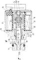
- the drawing shows a longitudinal section through a pressure control valve.
- the pressure control valve has a housing 10 which consists of a valve housing 11 and an approximately cup-shaped magnet housing 12.
- the magnet housing 12 is closed by a cover 13 which has a cylindrical extension 14 projecting into the interior of the housing.
- a continuous, stepped longitudinal bore 15A, 15B is formed in the extension, the bore section 15B of smaller diameter extending from the outside of the cover 13 being closed by an adjusting screw 16.
- a magnet coil 18 is inserted into the interior of the magnet housing, the inside diameter of which is larger than the outside diameter of the extension 14.
- an axially extending, triple graduated bore 21 extends, which penetrates the valve housing 11.
- the individual bore sections are continuously designated with 21A to 21D.
- the flat one formed between the bore portions 21D and 21C Shoulder serves as valve seat 22, which cooperates with the flat end face of a cylindrical valve body 23.
- the outer diameter of the end of the valve body 23 facing the valve seat 22 is smaller than the diameter of the bore section 21C.
- the opposite end of the valve body extends into the bore section 15A of the extension 14 and is supported there in a sliding ring 25 inserted into an annular groove 24.
- Another slide ring 26 is firmly inserted into the bore section 21B and also serves to mount the valve body 23.
- the valve seat 22 is connected via the bore section 21D to a pressure medium source (not shown), the connection of which is designated by A.
- the pressure medium outflow takes place via a transverse bore 28 which penetrates the valve housing in the region of the bore section 21C.
- the transverse bore 28 is connected to a container, not shown, the connection of which is denoted by 0.
- the end of the valve body protruding into the bore section 15A has an axially extending blind bore 29 extending from the end face, on the base of which a compression spring 30 is supported, the opposite end of which rests on the adjusting screw 16.
- the action of this spring 30 pushes the valve body 23 against the valve seat 22.
- An approximately cup-shaped magnet armature 31 is fastened to the valve body 23 in the area of the interior of the magnet coil 18 so that its bottom 32 faces the valve housing 11.
- the bottom has a longitudinal bore 33 which serves for frictional fastening.
- the outer diameter of the magnet armature 31 is somewhat smaller than the inner diameter of the coil 18, and its inner diameter is somewhat larger than the outer diameter of the extension 14 which projects into the interior of the magnet armature.
- the effect of the first spring 30 can be weakened or compensated for by this second spring 35, so that the characteristic curve of the valve can be set as desired.
- the pressure control valve is closed when the magnet is de-energized and port A is depressurized and the springs are set accordingly. H. the valve body 23 rests on the valve seat 22.
- the bore section 21D connected to the pressure medium source is thus closed on one side. If pressure builds up in the bore section 21D, the force on the end face of the valve body 23 exceeds a value which is greater than the difference between the forces by the spring 30 and by the counteracting spring 35, the valve body 23 lifts off its seat.
- the pressure medium connections A and O are connected via the bore sections 21D and 21C and the transverse bore 28, so that pressure medium can flow away.
- a pressure control or pressure reduction of the pressure medium flow flowing in at A is thus achieved for the purpose of actuating a consumer.
- pressure medium penetrates through the bearing gap between the slide ring 26 and the valve body 23 and thus reaches the interior of the magnet housing 12, so that the latter is filled with pressure medium.
- pressure medium continues to enter the bore section 15A.
- the pressure control valve is used, for example, in a transmission of a motor vehicle, the pressure control valve can be used in the Assembly must be filled with pressure medium and installed under the oil level. The magnet housing is then filled with pressure medium before installation and operation.
- the pressure required to open the valve can be increased by controlling the proportional solenoid accordingly.
- Hydraulic damping is achieved through the pressure medium filling of the magnet housing 12 and the long gaps between the magnet armature 31 and the solenoid coil 18, as well as between the magnet armature 31 and the extension 14, which also result in pressure medium, which reduces the instabilities of the control behavior.
- Another damping effect results from the change in volume of the pressure medium in the valve housing when the magnet armature and the valve body move. For this purpose, pressure medium must pass through the narrow bearing gaps between the sliding rings 25, 26 and the valve body 23. The resulting damping effect increases as the bearing clearance becomes smaller.
- the pressure control valve can be made particularly short.
- the axial working air gap between the magnet armature 31 and the base 20 of the magnet housing can be z. B. can be adjusted by an adjusting disc. As a result, this dimension is tool-dependent regardless of manufacturing and installation tolerances and therefore almost constant.
Landscapes
- Physics & Mathematics (AREA)
- Fluid Mechanics (AREA)
- General Physics & Mathematics (AREA)
- Engineering & Computer Science (AREA)
- Automation & Control Theory (AREA)
- Magnetically Actuated Valves (AREA)
- Safety Valves (AREA)
Abstract
Das Druckregelventil weist im einem Gehäuse einen zylinderförmigen Ventilkörper (23) auf, auf dem ein etwa becherförmiger Magnetanker (31) reibschlüssig befestigt ist. Der Magnetanker umfaßt zumindest teilweise einen der Magnetflußführung dienenden, in das Gehauseinnere ragenden Fortsatz (14). Der Regelbereich des Ventils kann durch einen Proportionalmagneten und durch zwei entgegengesetzt auf den Ventilkörper (23) wirkende Federn (30, 35) eingestellt werden.
Description
Die Erfindung geht aus von einem Druckregelventil nach der Gattung des Hauptanspruchs. Bei derartigen bekannten Ventilen ist der Regeldruck durch einen als Betätigungs- und Stelleinrichtung dienenden Proportionalmagneten einstellbar. Die Regelkennlinie eines solchen Druckregelventils ist in starkem Maße abhängig von Fertigungs- und Einbautoleranzen, insbesondere vom axialen Abstand des Magnetankers zum Ventilgehäuse bei gegebenem Abstand des Ventilkörpers vom Ventilsitz. Auftretende Streuungen verändern daher die Regelkennlinie einzelner Ventile in erheblichem Maße, so daß oft aufwendige Anpassungsmaßnahmen erforderlich sind. Darüberhinaus bauen derartige Druckregelventile lang und neigen im Regelbetrieb zu Instabilitäten, insbesondere zum Schwingen über den Einregelpunkt hinaus.The invention relates to a pressure control valve according to the preamble of the main claim. In such known valves, the control pressure is adjustable by means of a proportional magnet serving as an actuating and adjusting device. The control characteristic of such a pressure control valve depends to a large extent on manufacturing and installation tolerances, in particular on the axial distance of the magnet armature from the valve housing for a given distance of the valve body from the valve seat. Scattering thus changes the control characteristic of individual valves to a considerable extent, so that often complex adaptation measures are required. In addition, pressure control valves of this type are long and tend to become unstable during control operation, in particular to oscillate beyond the control point.
Das erfindungsgemäße Druckregelventil mit den kennzeichnenden Merkmalen des Hauptanspruchs hat demgegenüber den Vorteil, daß es sehr kurz baut und daß die Bewegungen des Ventilgliedes und des Ankers bei ölbefülltem Ankerraum gedämpft sind und daher ein Überschwingen über den Einstell- bzw. Regelwert hinaus verhindert wird. Durch den speziellen Aufbau des Ventils ist ein sehr genaues Einstellen des Abstandes zwischen Ventilsitz und Magnetanker möglich, so daß Fertigungs- und Einbautoleranzen ausgeglichen werden können.The pressure control valve according to the invention with the characterizing features of the main claim has the advantage that it is very short and that the movements of the valve member and the armature are damped in the oil-filled armature space and therefore overshoot beyond the setting or control value is prevented. By the The special structure of the valve enables a very precise adjustment of the distance between the valve seat and the magnet armature, so that manufacturing and installation tolerances can be compensated for.
Weitere vorteilhafte Ausgestaltungen der Erfindung ergeben sich aus den Unteransprüchen.Further advantageous embodiments of the invention result from the subclaims.
Ein Ausführungsbeispiel der Erfindung ist in der nachfolgenden Beschreibung und Zeichnung näher erläutert. Die Zeichnung zeigt einen Längsschnitt durch ein Druckregelventil.An embodiment of the invention is explained in more detail in the following description and drawing. The drawing shows a longitudinal section through a pressure control valve.
Das Druckregelventil weist ein Gehäuse 10 auf, das aus einem Ventilgehäuse 11 und einem etwa becherförmigen Magnetgehäuse 12 besteht. Das Magnetgehäuse 12 ist durch einen Deckel 13 verschlossen, welcher einen zylindrischen, in das Innere des Gehäuses ragenden Fortsatz 14 hat. Im Fortsatz ist eine durchgehende, abgestufte Längsbohrung 15A, 15B ausgebildet, deren von der Außenseite des Deckels 13 ausgehender Bohrungsabschnitt 15B kleineren Durchmessers durch eine Einstellschraube 16 verschlossen ist. In das Innere des Magnetgehäuses ist eine Magnetspule 18 eingesetzt, deren Innendurchmesser größer ist als der Außendurchmesser des Fortsatzes 14.The pressure control valve has a
Vom Boden 20 des Magnetgehäuses geht eine axial verlaufende, dreifach abgestufte Bohrung 21 aus, die das Ventilgehäuse 11 durchdringt. Die einzelnen Bohrungsabschnitte sind, ausgehend vom Boden 20 des Magnetgehäuses, fortlaufend mit 21A bis 21D bezeichnet. Die zwischen den Bohrungsabschnitten 21D und 21C ausgebildete flache Schulter dient als Ventilsitz 22, der mit der flachen Stirnseite eines zylinderförmigen Ventilkörpers 23 zusammenwirkt. Der Außendurchmesser des dem Ventilsitz 22 zugewandten Endes des Ventilkörpers 23 ist kleiner als der Durchmesser des Bohrungsabschnittes 21C. Das gegenüberliegende Ende des Ventilkörpers ragt bis in den Bohrungsabschnitt 15A des Fortsatzes 14 und ist dort in einem in eine Ringnut 24 eingesetzten Gleitring 25 gelagert. Ein weiterer Gleitring 26 ist in den Bohrungsabschnitt 21B fest eingesetzt und dient ebenfalls der Lagerung des Ventilkörpers 23. Der Ventilsitz 22 ist über den Bohrungsabschnitt 21D mit einer nicht dargestellten Druckmittelquelle verbunden, deren Anschluß mit A bezeichnet ist. Der Druckmittelabfluß erfolgt über eine Querbohrung 28, die das Ventilgehäuse im Bereich des Bohrungsabschnittes 21C durchdringt. Die Querbohrung 28 ist dazu mit einem nicht dargestellten Behälter verbunden, dessen Anschluß mit 0 bezeichnet ist.From the
Das in den Bohrungsabschnitt 15A ragende Ende des Ventilkörpers weist eine von der Stirnseite ausgehende, axial verlaufende Sackbohrung 29 auf, an deren Grund sich eine Druckfeder 30 abstützt, deren entgegengesetztes Ende an der Einstellschraube 16 anliegt. Durch die Wirkung dieser Feder 30 wird der Ventilkörper 23 gegen den Ventilsitz 22 gedrückt. Auf den Ventilkörper 23 ist im Bereich des Innenraums der Magnetspule 18 ein etwa becherförmiger Magnetanker 31 so reibschlüssig befestigt, daß sein Boden 32 zum Ventilgehäuse 11 weist. Der Boden hat dazu eine der reibschlüssigen Befestigung dienende Längsbohrung 33. Der Außendurchmesser des Magnetankers 31 ist etwas kleiner als der Innendurchmesser der Spule 18, und sein Innendurchmesser ist etwas größer als der Außendurchmesser des Fortsatzes 14, der in das Innere des Magnetankers ragt.The end of the valve body protruding into the bore section 15A has an axially extending
An der Unterseite des Bodens 32 des Magnetankers 31 befindet sich ein Absatz 34, der in den Bohrungsabschitt 21A ragt und dessen Durchmesser kleiner ist als der dieses Bohrungsabschnittes. An diesem Absatz 34 stützt sich eine zweite Druckfeder 35 ab, deren entgegengesetztes Ende an der Schulter 36 zwischen den Bohrungsabschnitten 21B und 21A anliegt.On the underside of the
Durch diese zweite Feder 35 kann die Wirkung der ersten Feder 30 abgeschwächt oder kompensiert werden, so daß die Kennlinie des Ventils beliebig einstellbar ist.The effect of the
Bei stromlosem Magneten und drucklosem Anschluß A sowie entsprechend eingestellten Federn ist das Druckregelventil geschlossen d. h. der Ventilkörper 23 liegt am Ventilsitz 22 an. Damit ist der mit der Druckmittelquelle verbundene Bohrungsabschnitt 21D einseitig verschlossen. Übersteigt durch Druckaufbau im Bohrungsabschnitt 21D die Kraft auf die Stirnfläche des Ventilkörpers 23 einen Wert, der größer ist als die Differenz der Kräfte durch die Feder 30 und durch die entgegenwirkende Feder 35, hebt der Ventilkörper 23 von seinem Sitz ab. Dadurch sind über die Bohrungsabschnitte 21D und 21C sowie die Querbohrung 28 die Druckmittelanschlüsse A und O verbunden, so daß Druckmittel abfließen kann. Damit erreicht man eine Druckregelung bzw. Druckminderung des bei A zufließenden Druckmittelstroms zwecks Betätigung eines Verbrauchers. Gleichzeitig dringt Druckmittel durch den Lagerspalt zwischen Gleitring 26 und Ventilkörper 23 und gelangt somit in das Innere des Magnetgehäuses 12, so daß dieses mit Druckmittel gefüllt ist. Durch den Lagerspalt zwischen Gleitring 25 und Ventilkörper 23 gelangt Druckmittel weiterhin in den Bohrungsabschnitt 15A.The pressure control valve is closed when the magnet is de-energized and port A is depressurized and the springs are set accordingly. H. the valve body 23 rests on the
Wird das Druckregelventil beispielsweise in einem Getriebe eines Kraftfahrzeuges eingesetzt, kann das Druckregelventil bei der Montage mit Druckmittel aufgefüllt werden und unter dem Ölspiegel eingebaut werden. Das Magnetgehäuse ist dann schon vor Einbau und Betätigung druckmittelgefüllt.If the pressure control valve is used, for example, in a transmission of a motor vehicle, the pressure control valve can be used in the Assembly must be filled with pressure medium and installed under the oil level. The magnet housing is then filled with pressure medium before installation and operation.
Durch entsprechende Ansteuerung des Proportionalmagneten kann der Druck erhöht werden, der nötig ist, das Ventil zu öffnen.The pressure required to open the valve can be increased by controlling the proportional solenoid accordingly.
Durch die Druckmittelfüllung des Magnetgehäuses 12 und die dadurch ebenfalls druckmittelgefüllten langen Spalte zwischen Magnetanker 31 und Magnetspule 18 sowie zwischen Magnetanker 31 und Fortsatz 14 wird eine hydraulische Dämpfung erreicht, die Instabilitäten des Regelverhaltens vermindert. Ein weiterer Dämpfungseffekt ergibt sich durch die Volumenänderung des im Ventilgehäuses befindlichen Druckmittels bei Bewegung des Magnetankers und des Ventilkörpers. Dazu muß Druckmittel durch die schmalen Lagerspalte zwischen den Gleitringen 25, 26 und dem Ventilkörper 23 durchtreten. Der sich dadurch einstellende weitere Dämpfungseffekt nimmt mit kleiner werdendem Lagerspiel zu.Hydraulic damping is achieved through the pressure medium filling of the
Durch die Formgebung des Magnetankers, der den dem Magnetfluß dienenden Fortsatz 14 teilweise umfängt, kann das Druckregelventil besonders kurz bauen.Due to the shape of the magnet armature, which partially surrounds the
Durch die reibschlüssige Befestigung des Ankers auf dem Ventilkörper kann bei der Montage des Druckregelventils der axiale Arbeitsluftspalt zwischen Magnetanker 31 und Boden 20 des Magnetgehäuses in Bezug auf den Ventilsitz 22 z. B. durch eine Justierscheibe eingestellt werden. Dadurch ist dieses Maß unabhängig von Fertigungs- und Einbautoleranzen werkzeuggebunden und daher nahezu konstant.Due to the frictional fastening of the armature on the valve body, the axial working air gap between the
Durch die weit auseinanderliegenden Lagerstellen des Ventilkörpers und damit des Magnetankers kann deren Exzentrizität sehr gering gehalten werden. Dadurch werden die magnetischen Querkräfte und damit die Hysterese der Regelkurve des Ventils ebenfalls klein gehalten.Due to the widely spaced bearing locations of the valve body and thus the magnet armature, their eccentricity can be kept very low. This also keeps the magnetic transverse forces and thus the hysteresis of the control curve of the valve low.
Claims (4)
Applications Claiming Priority (2)
| Application Number | Priority Date | Filing Date | Title |
|---|---|---|---|
| DE4035853 | 1990-11-10 | ||
| DE4035853A DE4035853C2 (en) | 1990-11-10 | 1990-11-10 | Pressure control valve |
Publications (3)
| Publication Number | Publication Date |
|---|---|
| EP0485737A2 true EP0485737A2 (en) | 1992-05-20 |
| EP0485737A3 EP0485737A3 (en) | 1992-07-22 |
| EP0485737B1 EP0485737B1 (en) | 1996-01-03 |
Family
ID=6418040
Family Applications (1)
| Application Number | Title | Priority Date | Filing Date |
|---|---|---|---|
| EP91117188A Expired - Lifetime EP0485737B1 (en) | 1990-11-10 | 1991-10-09 | Pressure control valve |
Country Status (3)
| Country | Link |
|---|---|
| US (1) | US5284317A (en) |
| EP (1) | EP0485737B1 (en) |
| DE (2) | DE4035853C2 (en) |
Cited By (4)
| Publication number | Priority date | Publication date | Assignee | Title |
|---|---|---|---|---|
| EP0711944A1 (en) * | 1994-11-10 | 1996-05-15 | Saturn Electronics & Engineering, Inc. | Proportional variable force solenoid control valve and transmission fluid control device |
| FR2735883A1 (en) * | 1995-06-23 | 1996-12-27 | Eaton Sa Monaco | HYDRAULIC FLOW REGULATOR |
| EP0785558A3 (en) * | 1996-01-16 | 1997-11-19 | Saturn Electronics & Engineering, Inc. | Proportional variable force solenoid control valve |
| WO2009065735A1 (en) * | 2007-11-19 | 2009-05-28 | Continental Teves Ag & Co. Ohg | Pressure regulating valve |
Families Citing this family (14)
| Publication number | Priority date | Publication date | Assignee | Title |
|---|---|---|---|---|
| DE4326507C2 (en) * | 1993-08-06 | 1996-06-05 | Bosch Gmbh Robert | Electromagnetically actuated proportional valve |
| DE19606318C2 (en) * | 1996-02-21 | 2003-01-02 | Zahnradfabrik Friedrichshafen | Pressure regulator for electro-hydraulic transmission controls |
| US5752689A (en) * | 1996-11-26 | 1998-05-19 | Servojet Products International | Solenoid valve assembly with armature guide and fuel injection system incorporating such a valve |
| DE19905721A1 (en) * | 1998-02-24 | 1999-08-26 | Hoerbiger Ventilwerke Gmbh | Electromagnetically actuated gas valve for use as a fuel injection valve in a gas engine |
| US6778049B1 (en) | 1999-10-01 | 2004-08-17 | Siemens Automotive Corporation | Apparatus and method for changing the dynamic response of an electromagnetically operated actuator |
| DE102006027349A1 (en) * | 2006-06-13 | 2007-12-20 | Schaeffler Kg | Camshaft adjuster with an electromagnetic actuator |
| DE102008060889B4 (en) * | 2008-12-09 | 2022-08-25 | Pierburg Gmbh | pressure control valve |
| US8317157B2 (en) * | 2008-12-15 | 2012-11-27 | Continental Automotive Systems Us, Inc. | Automobile high pressure pump solenoid valve |
| EP2524161B1 (en) * | 2010-01-12 | 2017-09-27 | BorgWarner Inc. | Solenoid with spring plug |
| WO2013186859A1 (en) * | 2012-06-12 | 2013-12-19 | トヨタ自動車株式会社 | Normally closed solenoid valve |
| CN104321576B (en) | 2012-06-21 | 2016-08-24 | 博格华纳公司 | For there being the solenoid motor method of ventilation polluting protection via hydraulic sleeve pipe racks |
| US9777865B2 (en) | 2014-04-15 | 2017-10-03 | Fema Corporation Of Michigan | Balanced electronically controlled pressure regulating valve |
| DE102016205102B4 (en) * | 2015-12-17 | 2022-01-05 | Robert Bosch Gmbh | Valve in a high pressure pump of a fuel injection system and high pressure pump of a fuel injection system with this valve |
| DE102017201518A1 (en) | 2017-01-31 | 2018-08-02 | Zf Friedrichshafen Ag | Valve device with an adjustable pressure valve |
Family Cites Families (13)
| Publication number | Priority date | Publication date | Assignee | Title |
|---|---|---|---|---|
| CH405843A (en) * | 1963-11-15 | 1966-01-15 | Eldima Ag | Electromagnetic drive magnet and use of the same as part of an electrovalve |
| SE363683B (en) * | 1971-08-20 | 1974-01-28 | Haegglund & Soener Ab | |
| DE2255272B2 (en) * | 1972-11-11 | 1979-04-05 | Robert Bosch Gmbh, 7000 Stuttgart | Actuating magnet with a housing |
| GB1467363A (en) * | 1973-07-20 | 1977-03-16 | Daimler Benz Ag | Solenoid valve |
| US4081774A (en) * | 1976-04-12 | 1978-03-28 | Barber-Colman Company | Actuating device |
| US4361309A (en) * | 1980-06-23 | 1982-11-30 | Niipondenso Co., Ltd. | Electromagnetic actuator |
| JPS5840672U (en) * | 1981-09-14 | 1983-03-17 | 株式会社デンソー | Solenoid reed valve |
| DE3144362A1 (en) * | 1981-11-07 | 1983-05-19 | Robert Bosch Gmbh, 7000 Stuttgart | Actuator which can be operated electromagnetically |
| US4875658A (en) * | 1986-10-08 | 1989-10-24 | Mitsubishi Jidosha Kogyo Kabushiki Kaisha | Electromagnetic valve |
| DE3705082A1 (en) * | 1987-02-18 | 1988-09-01 | Geze Gmbh | Solenoid valve |
| DE3709474C1 (en) * | 1987-03-23 | 1988-03-31 | Bosch Gmbh Robert | Solenoid valve |
| US4966195A (en) * | 1987-06-25 | 1990-10-30 | Colt Industries Inc. | Transmission pressure regulator |
| IT1211628B (en) * | 1987-12-24 | 1989-11-03 | Weber Srl | ELECTROMAGNETIC CONTROL VALVE FOR THE CONTROL OF A AIR FLOW RATE IN A FUEL SUPPLY DEVICE FOR INTERNAL COMBUSTION ENGINE |
-
1990
- 1990-11-10 DE DE4035853A patent/DE4035853C2/en not_active Expired - Fee Related
-
1991
- 1991-09-20 US US07/764,139 patent/US5284317A/en not_active Expired - Lifetime
- 1991-10-09 DE DE59107206T patent/DE59107206D1/en not_active Expired - Fee Related
- 1991-10-09 EP EP91117188A patent/EP0485737B1/en not_active Expired - Lifetime
Cited By (10)
| Publication number | Priority date | Publication date | Assignee | Title |
|---|---|---|---|---|
| EP0711944A1 (en) * | 1994-11-10 | 1996-05-15 | Saturn Electronics & Engineering, Inc. | Proportional variable force solenoid control valve and transmission fluid control device |
| US5611370A (en) * | 1994-11-10 | 1997-03-18 | Saturn Electronics & Engineering, Inc. | Proportional variable force solenoid control valve and transmission fluid control device |
| US5921526A (en) * | 1994-11-10 | 1999-07-13 | Saturn Electronics & Engineering, Inc. | Proportional variable force solenoid control valve and transmission fluid control device |
| US6109300A (en) * | 1994-11-10 | 2000-08-29 | Saturn Electronics & Engineering, Inc. | Proportional variable force solenoid control valve and transmission fluid control device |
| FR2735883A1 (en) * | 1995-06-23 | 1996-12-27 | Eaton Sa Monaco | HYDRAULIC FLOW REGULATOR |
| EP0750241A3 (en) * | 1995-06-23 | 1997-01-02 | Eaton S.A.M. | Hydraulic flow controller |
| EP0785558A3 (en) * | 1996-01-16 | 1997-11-19 | Saturn Electronics & Engineering, Inc. | Proportional variable force solenoid control valve |
| US5996628A (en) * | 1996-01-16 | 1999-12-07 | Saturn Electronics & Engineering, Inc. | Proportional variable force solenoid control valve |
| WO2009065735A1 (en) * | 2007-11-19 | 2009-05-28 | Continental Teves Ag & Co. Ohg | Pressure regulating valve |
| US8505873B2 (en) | 2007-11-19 | 2013-08-13 | Continental Teves Ag & Co. Ohg | Pressure regulating valve |
Also Published As
| Publication number | Publication date |
|---|---|
| DE4035853A1 (en) | 1992-05-14 |
| US5284317A (en) | 1994-02-08 |
| EP0485737A3 (en) | 1992-07-22 |
| DE59107206D1 (en) | 1996-02-15 |
| EP0485737B1 (en) | 1996-01-03 |
| DE4035853C2 (en) | 1994-02-24 |
Similar Documents
| Publication | Publication Date | Title |
|---|---|---|
| EP0485737B1 (en) | Pressure control valve | |
| EP0773877B1 (en) | Valve device, in particular for hydraulic brake systems with abs or drive-slip control, and a method of adjusting a valve device | |
| DE4442085C2 (en) | Electromagnetically operated proportional pressure control valve | |
| DE19959324B4 (en) | Solenoid control valve | |
| DE69528114T2 (en) | Electrically modulated pressure control valve with an electromagnet with adjustable force | |
| EP0285909B1 (en) | Shock absorber | |
| EP0399326B1 (en) | Shockabsorber | |
| DE3823430C3 (en) | Hydraulic telescopic shock absorber | |
| DE19907732B4 (en) | Hydraulic solenoid valve | |
| EP0318816A2 (en) | Hydraulic shock and vibration damper with adjustable damping | |
| DE112020001540T5 (en) | Shock absorber with adjustable damping force | |
| DE69023793T2 (en) | Pressure control valve. | |
| DE4132262A1 (en) | HYDRAULIC VIBRATION DAMPER FOR MOTOR VEHICLES | |
| DE3144362A1 (en) | Actuator which can be operated electromagnetically | |
| EP0627052A1 (en) | Damper valve and process for continuously adjusting the damping force of an adjustable oscillation damper. | |
| DE19943066A1 (en) | Electromagnetically operable hydraulic proportional valve has closing member with in region of end facing valve seat, cone-shaped sealing member whose smaller end faces valve seat | |
| DE69616007T2 (en) | Adjustable damping valve | |
| DE4190781C2 (en) | Hydraulic vibration damper for a motor vehicle | |
| DE10104622B4 (en) | Hydraulic pressure control valve | |
| DE10120510A1 (en) | Solenoid actuated drive device and damping force regulating hydraulic shock absorber using them | |
| DE2206751C2 (en) | Pressure regulating valve for automobile automatic transmission - matches working pressure to engine load via electromagnet receiving pressure setting signal | |
| DE3830343A1 (en) | DAMPING FORCE CHANGEABLE, HYDRAULIC VIBRATION DAMPER | |
| DE4324589C2 (en) | Electromagnetically operated pressure control valve | |
| DE4326507C2 (en) | Electromagnetically actuated proportional valve | |
| DE3942437C3 (en) | Gas valve |
Legal Events
| Date | Code | Title | Description |
|---|---|---|---|
| PUAI | Public reference made under article 153(3) epc to a published international application that has entered the european phase |
Free format text: ORIGINAL CODE: 0009012 |
|
| AK | Designated contracting states |
Kind code of ref document: A2 Designated state(s): DE FR GB |
|
| PUAL | Search report despatched |
Free format text: ORIGINAL CODE: 0009013 |
|
| AK | Designated contracting states |
Kind code of ref document: A3 Designated state(s): DE FR GB |
|
| 17P | Request for examination filed |
Effective date: 19921127 |
|
| 17Q | First examination report despatched |
Effective date: 19940923 |
|
| GRAA | (expected) grant |
Free format text: ORIGINAL CODE: 0009210 |
|
| AK | Designated contracting states |
Kind code of ref document: B1 Designated state(s): DE FR GB |
|
| ET | Fr: translation filed | ||
| REF | Corresponds to: |
Ref document number: 59107206 Country of ref document: DE Date of ref document: 19960215 |
|
| GBT | Gb: translation of ep patent filed (gb section 77(6)(a)/1977) |
Effective date: 19960314 |
|
| PGFP | Annual fee paid to national office [announced via postgrant information from national office to epo] |
Ref country code: GB Payment date: 19960926 Year of fee payment: 6 |
|
| PGFP | Annual fee paid to national office [announced via postgrant information from national office to epo] |
Ref country code: FR Payment date: 19961011 Year of fee payment: 6 |
|
| PLBE | No opposition filed within time limit |
Free format text: ORIGINAL CODE: 0009261 |
|
| STAA | Information on the status of an ep patent application or granted ep patent |
Free format text: STATUS: NO OPPOSITION FILED WITHIN TIME LIMIT |
|
| 26N | No opposition filed | ||
| PG25 | Lapsed in a contracting state [announced via postgrant information from national office to epo] |
Ref country code: GB Free format text: LAPSE BECAUSE OF NON-PAYMENT OF DUE FEES Effective date: 19971009 |
|
| PG25 | Lapsed in a contracting state [announced via postgrant information from national office to epo] |
Ref country code: FR Free format text: THE PATENT HAS BEEN ANNULLED BY A DECISION OF A NATIONAL AUTHORITY Effective date: 19971031 |
|
| GBPC | Gb: european patent ceased through non-payment of renewal fee |
Effective date: 19971009 |
|
| REG | Reference to a national code |
Ref country code: FR Ref legal event code: ST |
|
| PGFP | Annual fee paid to national office [announced via postgrant information from national office to epo] |
Ref country code: DE Payment date: 20041222 Year of fee payment: 14 |
|
| PG25 | Lapsed in a contracting state [announced via postgrant information from national office to epo] |
Ref country code: DE Free format text: LAPSE BECAUSE OF NON-PAYMENT OF DUE FEES Effective date: 20060503 |