EP0485737A2 - Soupape de régulation de pression - Google Patents
Soupape de régulation de pression Download PDFInfo
- Publication number
- EP0485737A2 EP0485737A2 EP91117188A EP91117188A EP0485737A2 EP 0485737 A2 EP0485737 A2 EP 0485737A2 EP 91117188 A EP91117188 A EP 91117188A EP 91117188 A EP91117188 A EP 91117188A EP 0485737 A2 EP0485737 A2 EP 0485737A2
- Authority
- EP
- European Patent Office
- Prior art keywords
- valve
- valve body
- housing
- pressure control
- control valve
- Prior art date
- Legal status (The legal status is an assumption and is not a legal conclusion. Google has not performed a legal analysis and makes no representation as to the accuracy of the status listed.)
- Granted
Links
Images
Classifications
-
- G—PHYSICS
- G05—CONTROLLING; REGULATING
- G05D—SYSTEMS FOR CONTROLLING OR REGULATING NON-ELECTRIC VARIABLES
- G05D16/00—Control of fluid pressure
- G05D16/20—Control of fluid pressure characterised by the use of electric means
- G05D16/2006—Control of fluid pressure characterised by the use of electric means with direct action of electric energy on controlling means
- G05D16/2013—Control of fluid pressure characterised by the use of electric means with direct action of electric energy on controlling means using throttling means as controlling means
- G05D16/2022—Control of fluid pressure characterised by the use of electric means with direct action of electric energy on controlling means using throttling means as controlling means actuated by a proportional solenoid
Definitions
- the invention relates to a pressure control valve according to the preamble of the main claim.
- the control pressure is adjustable by means of a proportional magnet serving as an actuating and adjusting device.
- the control characteristic of such a pressure control valve depends to a large extent on manufacturing and installation tolerances, in particular on the axial distance of the magnet armature from the valve housing for a given distance of the valve body from the valve seat. Scattering thus changes the control characteristic of individual valves to a considerable extent, so that often complex adaptation measures are required.
- pressure control valves of this type are long and tend to become unstable during control operation, in particular to oscillate beyond the control point.
- the pressure control valve according to the invention with the characterizing features of the main claim has the advantage that it is very short and that the movements of the valve member and the armature are damped in the oil-filled armature space and therefore overshoot beyond the setting or control value is prevented.
- the special structure of the valve enables a very precise adjustment of the distance between the valve seat and the magnet armature, so that manufacturing and installation tolerances can be compensated for.
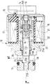
- the drawing shows a longitudinal section through a pressure control valve.
- the pressure control valve has a housing 10 which consists of a valve housing 11 and an approximately cup-shaped magnet housing 12.
- the magnet housing 12 is closed by a cover 13 which has a cylindrical extension 14 projecting into the interior of the housing.
- a continuous, stepped longitudinal bore 15A, 15B is formed in the extension, the bore section 15B of smaller diameter extending from the outside of the cover 13 being closed by an adjusting screw 16.
- a magnet coil 18 is inserted into the interior of the magnet housing, the inside diameter of which is larger than the outside diameter of the extension 14.
- an axially extending, triple graduated bore 21 extends, which penetrates the valve housing 11.
- the individual bore sections are continuously designated with 21A to 21D.
- the flat one formed between the bore portions 21D and 21C Shoulder serves as valve seat 22, which cooperates with the flat end face of a cylindrical valve body 23.
- the outer diameter of the end of the valve body 23 facing the valve seat 22 is smaller than the diameter of the bore section 21C.
- the opposite end of the valve body extends into the bore section 15A of the extension 14 and is supported there in a sliding ring 25 inserted into an annular groove 24.
- Another slide ring 26 is firmly inserted into the bore section 21B and also serves to mount the valve body 23.
- the valve seat 22 is connected via the bore section 21D to a pressure medium source (not shown), the connection of which is designated by A.
- the pressure medium outflow takes place via a transverse bore 28 which penetrates the valve housing in the region of the bore section 21C.
- the transverse bore 28 is connected to a container, not shown, the connection of which is denoted by 0.
- the end of the valve body protruding into the bore section 15A has an axially extending blind bore 29 extending from the end face, on the base of which a compression spring 30 is supported, the opposite end of which rests on the adjusting screw 16.
- the action of this spring 30 pushes the valve body 23 against the valve seat 22.
- An approximately cup-shaped magnet armature 31 is fastened to the valve body 23 in the area of the interior of the magnet coil 18 so that its bottom 32 faces the valve housing 11.
- the bottom has a longitudinal bore 33 which serves for frictional fastening.
- the outer diameter of the magnet armature 31 is somewhat smaller than the inner diameter of the coil 18, and its inner diameter is somewhat larger than the outer diameter of the extension 14 which projects into the interior of the magnet armature.
- the effect of the first spring 30 can be weakened or compensated for by this second spring 35, so that the characteristic curve of the valve can be set as desired.
- the pressure control valve is closed when the magnet is de-energized and port A is depressurized and the springs are set accordingly. H. the valve body 23 rests on the valve seat 22.
- the bore section 21D connected to the pressure medium source is thus closed on one side. If pressure builds up in the bore section 21D, the force on the end face of the valve body 23 exceeds a value which is greater than the difference between the forces by the spring 30 and by the counteracting spring 35, the valve body 23 lifts off its seat.
- the pressure medium connections A and O are connected via the bore sections 21D and 21C and the transverse bore 28, so that pressure medium can flow away.
- a pressure control or pressure reduction of the pressure medium flow flowing in at A is thus achieved for the purpose of actuating a consumer.
- pressure medium penetrates through the bearing gap between the slide ring 26 and the valve body 23 and thus reaches the interior of the magnet housing 12, so that the latter is filled with pressure medium.
- pressure medium continues to enter the bore section 15A.
- the pressure control valve is used, for example, in a transmission of a motor vehicle, the pressure control valve can be used in the Assembly must be filled with pressure medium and installed under the oil level. The magnet housing is then filled with pressure medium before installation and operation.
- the pressure required to open the valve can be increased by controlling the proportional solenoid accordingly.
- Hydraulic damping is achieved through the pressure medium filling of the magnet housing 12 and the long gaps between the magnet armature 31 and the solenoid coil 18, as well as between the magnet armature 31 and the extension 14, which also result in pressure medium, which reduces the instabilities of the control behavior.
- Another damping effect results from the change in volume of the pressure medium in the valve housing when the magnet armature and the valve body move. For this purpose, pressure medium must pass through the narrow bearing gaps between the sliding rings 25, 26 and the valve body 23. The resulting damping effect increases as the bearing clearance becomes smaller.
- the pressure control valve can be made particularly short.
- the axial working air gap between the magnet armature 31 and the base 20 of the magnet housing can be z. B. can be adjusted by an adjusting disc. As a result, this dimension is tool-dependent regardless of manufacturing and installation tolerances and therefore almost constant.
Landscapes
- Physics & Mathematics (AREA)
- Fluid Mechanics (AREA)
- General Physics & Mathematics (AREA)
- Engineering & Computer Science (AREA)
- Automation & Control Theory (AREA)
- Magnetically Actuated Valves (AREA)
- Safety Valves (AREA)
Applications Claiming Priority (2)
| Application Number | Priority Date | Filing Date | Title |
|---|---|---|---|
| DE4035853A DE4035853C2 (de) | 1990-11-10 | 1990-11-10 | Druckregelventil |
| DE4035853 | 1990-11-10 |
Publications (3)
| Publication Number | Publication Date |
|---|---|
| EP0485737A2 true EP0485737A2 (fr) | 1992-05-20 |
| EP0485737A3 EP0485737A3 (en) | 1992-07-22 |
| EP0485737B1 EP0485737B1 (fr) | 1996-01-03 |
Family
ID=6418040
Family Applications (1)
| Application Number | Title | Priority Date | Filing Date |
|---|---|---|---|
| EP91117188A Expired - Lifetime EP0485737B1 (fr) | 1990-11-10 | 1991-10-09 | Soupape de régulation de pression |
Country Status (3)
| Country | Link |
|---|---|
| US (1) | US5284317A (fr) |
| EP (1) | EP0485737B1 (fr) |
| DE (2) | DE4035853C2 (fr) |
Cited By (4)
| Publication number | Priority date | Publication date | Assignee | Title |
|---|---|---|---|---|
| EP0711944A1 (fr) * | 1994-11-10 | 1996-05-15 | Saturn Electronics & Engineering, Inc. | Soupape électromagnétique de contrÔle proportionnel et appareil de commande de transmission |
| FR2735883A1 (fr) * | 1995-06-23 | 1996-12-27 | Eaton Sa Monaco | Regulateur hydraulique de debit |
| EP0785558A3 (fr) * | 1996-01-16 | 1997-11-19 | Saturn Electronics & Engineering, Inc. | Vanne électromagnétique proportionnelle avec force de commande variable |
| WO2009065735A1 (fr) * | 2007-11-19 | 2009-05-28 | Continental Teves Ag & Co. Ohg | Soupape de réglage de pression |
Families Citing this family (14)
| Publication number | Priority date | Publication date | Assignee | Title |
|---|---|---|---|---|
| DE4326507C2 (de) * | 1993-08-06 | 1996-06-05 | Bosch Gmbh Robert | Elektromagnetisch betätigbares Proportionalventil |
| DE19606318C2 (de) * | 1996-02-21 | 2003-01-02 | Zahnradfabrik Friedrichshafen | Druckregler für elektro-hydraulische Getriebesteuerungen |
| US5752689A (en) * | 1996-11-26 | 1998-05-19 | Servojet Products International | Solenoid valve assembly with armature guide and fuel injection system incorporating such a valve |
| DE19905721A1 (de) * | 1998-02-24 | 1999-08-26 | Hoerbiger Ventilwerke Gmbh | Gasventil |
| US6778049B1 (en) | 1999-10-01 | 2004-08-17 | Siemens Automotive Corporation | Apparatus and method for changing the dynamic response of an electromagnetically operated actuator |
| DE102006027349A1 (de) * | 2006-06-13 | 2007-12-20 | Schaeffler Kg | Nockenwellenversteller mit einem elektromagnetischen Aktuator |
| DE102008060889B4 (de) * | 2008-12-09 | 2022-08-25 | Pierburg Gmbh | Druckregelventil |
| US8317157B2 (en) * | 2008-12-15 | 2012-11-27 | Continental Automotive Systems Us, Inc. | Automobile high pressure pump solenoid valve |
| EP2524161B1 (fr) * | 2010-01-12 | 2017-09-27 | BorgWarner Inc. | Solénoïde doté d'un tampon de ressort |
| US9366354B2 (en) * | 2012-06-12 | 2016-06-14 | Toyota Jidosha Kabushiki Kaisha | Normally closed solenoid valve |
| US9423045B2 (en) | 2012-06-21 | 2016-08-23 | Borgwarner Inc. | Method for solenoid motor venting with contamination protection via a hydraulic sleeve |
| US9777865B2 (en) | 2014-04-15 | 2017-10-03 | Fema Corporation Of Michigan | Balanced electronically controlled pressure regulating valve |
| DE102016205102B4 (de) * | 2015-12-17 | 2022-01-05 | Robert Bosch Gmbh | Ventil in einer Hochdruckpumpe eines Kraftstoffeinspritzsystems und Hochdruckpumpe eines Kraftstoffeinspritzsystems mit diesem Ventil |
| DE102017201518A1 (de) | 2017-01-31 | 2018-08-02 | Zf Friedrichshafen Ag | Ventilvorrichtung mit einem verstellbaren Druckventil |
Family Cites Families (13)
| Publication number | Priority date | Publication date | Assignee | Title |
|---|---|---|---|---|
| CH405843A (de) * | 1963-11-15 | 1966-01-15 | Eldima Ag | Elektromagnetischer Antriebsmagnet und Verwendung desselben als Bestandteil eines Elektroventils |
| SE363683B (fr) * | 1971-08-20 | 1974-01-28 | Haegglund & Soener Ab | |
| DE2255272B2 (de) * | 1972-11-11 | 1979-04-05 | Robert Bosch Gmbh, 7000 Stuttgart | Stellmagnet mit einem Gehäuse |
| GB1467363A (en) * | 1973-07-20 | 1977-03-16 | Daimler Benz Ag | Solenoid valve |
| US4081774A (en) * | 1976-04-12 | 1978-03-28 | Barber-Colman Company | Actuating device |
| US4361309A (en) * | 1980-06-23 | 1982-11-30 | Niipondenso Co., Ltd. | Electromagnetic actuator |
| JPS5840672U (ja) * | 1981-09-14 | 1983-03-17 | 株式会社デンソー | 電磁式リ−ド弁 |
| DE3144362A1 (de) * | 1981-11-07 | 1983-05-19 | Robert Bosch Gmbh, 7000 Stuttgart | Elektromagnetisch betaetigbares stellglied |
| KR880005354A (ko) * | 1986-10-08 | 1988-06-28 | 나까무라 겐조 | 전자 작동기 |
| DE3705082A1 (de) * | 1987-02-18 | 1988-09-01 | Geze Gmbh | Magnetventil |
| DE3709474C1 (en) * | 1987-03-23 | 1988-03-31 | Bosch Gmbh Robert | Solenoid valve |
| US4966195A (en) * | 1987-06-25 | 1990-10-30 | Colt Industries Inc. | Transmission pressure regulator |
| IT1211628B (it) * | 1987-12-24 | 1989-11-03 | Weber Srl | Valvola a comando elettromagnetico per il controllo di una portata d aria in un dispositivo di alimentazione del carburante per motore acombustione interna |
-
1990
- 1990-11-10 DE DE4035853A patent/DE4035853C2/de not_active Expired - Fee Related
-
1991
- 1991-09-20 US US07/764,139 patent/US5284317A/en not_active Expired - Lifetime
- 1991-10-09 EP EP91117188A patent/EP0485737B1/fr not_active Expired - Lifetime
- 1991-10-09 DE DE59107206T patent/DE59107206D1/de not_active Expired - Fee Related
Cited By (10)
| Publication number | Priority date | Publication date | Assignee | Title |
|---|---|---|---|---|
| EP0711944A1 (fr) * | 1994-11-10 | 1996-05-15 | Saturn Electronics & Engineering, Inc. | Soupape électromagnétique de contrÔle proportionnel et appareil de commande de transmission |
| US5611370A (en) * | 1994-11-10 | 1997-03-18 | Saturn Electronics & Engineering, Inc. | Proportional variable force solenoid control valve and transmission fluid control device |
| US5921526A (en) * | 1994-11-10 | 1999-07-13 | Saturn Electronics & Engineering, Inc. | Proportional variable force solenoid control valve and transmission fluid control device |
| US6109300A (en) * | 1994-11-10 | 2000-08-29 | Saturn Electronics & Engineering, Inc. | Proportional variable force solenoid control valve and transmission fluid control device |
| FR2735883A1 (fr) * | 1995-06-23 | 1996-12-27 | Eaton Sa Monaco | Regulateur hydraulique de debit |
| EP0750241A3 (fr) * | 1995-06-23 | 1997-01-02 | Eaton S.A.M. | Régulateur hydraulique de débit |
| EP0785558A3 (fr) * | 1996-01-16 | 1997-11-19 | Saturn Electronics & Engineering, Inc. | Vanne électromagnétique proportionnelle avec force de commande variable |
| US5996628A (en) * | 1996-01-16 | 1999-12-07 | Saturn Electronics & Engineering, Inc. | Proportional variable force solenoid control valve |
| WO2009065735A1 (fr) * | 2007-11-19 | 2009-05-28 | Continental Teves Ag & Co. Ohg | Soupape de réglage de pression |
| US8505873B2 (en) | 2007-11-19 | 2013-08-13 | Continental Teves Ag & Co. Ohg | Pressure regulating valve |
Also Published As
| Publication number | Publication date |
|---|---|
| EP0485737B1 (fr) | 1996-01-03 |
| DE4035853A1 (de) | 1992-05-14 |
| DE4035853C2 (de) | 1994-02-24 |
| DE59107206D1 (de) | 1996-02-15 |
| US5284317A (en) | 1994-02-08 |
| EP0485737A3 (en) | 1992-07-22 |
Similar Documents
| Publication | Publication Date | Title |
|---|---|---|
| EP0485737B1 (fr) | Soupape de régulation de pression | |
| EP0773877B1 (fr) | Dispositif a soupape, notamment pour des systemes de freins hydrauliques equipes d'antiblocage ou et/ou d'antipatinage, et procede de reglage d'un dispositif a soupape | |
| DE4442085C2 (de) | Elektromagnetisch betätigbares Proportionaldruckregelventil | |
| DE19959324B4 (de) | Solenoid-Steuerventil | |
| EP0285909B1 (fr) | Amortisseur de chocs | |
| EP0399326B1 (fr) | Amortisseur de choc | |
| EP1046005B1 (fr) | Soupape proportionnelle hydraulique a actionnement electromagnetique | |
| DE3823430C3 (de) | Hydraulischer Teleskopstoßdämpfer | |
| DE19907732B4 (de) | Hydraulisches Magnetventil | |
| DE69715712T2 (de) | Hydraulisches Elektromagnetventil | |
| EP0318816A2 (fr) | Amortisseur hydraulique de chocs et de vibrations à amortissement réglable | |
| DE4132262A1 (de) | Hydraulischer regelbarer schwingungsdaempfer fuer kraftfahrzeuge | |
| DE3144362A1 (de) | Elektromagnetisch betaetigbares stellglied | |
| DE112020001540T5 (de) | In der Dämpfungskraft verstellbarer Stoßdämpfer | |
| EP0627052A1 (fr) | Soupape d'amortisseur et procede de reglage continu de la force d'amortissement d'un amortisseur de vibrations reglable. | |
| DE69616007T2 (de) | Regelbares Dämpfungsventil | |
| DE68916435T2 (de) | Schnell ansprechendes, druckausgeglichenes, elektromagnetisches hochdruck-steuerventil. | |
| DE4190781C2 (de) | Hydraulischer Schwingungsdämpfer für ein Kraftfahrzeug | |
| DE10104622B4 (de) | Hydraulisches Druckregelventil | |
| DE10120510A1 (de) | Solenoidbetätigte Antriebsvorrichtung und Dämpfkraftregelnder Hydraulischer Stossdämpfer der diese verwendet | |
| DE2206751C2 (de) | Regelventil für den Arbeitsdruck eines automatisch geschalteten Getriebes für Fahrzeuge, insbesondere Kraftfahrzeuge | |
| DE3830343A1 (de) | Daempfkraftveraenderbarer, hydraulischer schwingungsdaempfer | |
| DE4324589C2 (de) | Elektromagnetisch betätigbares Druckregelventil | |
| DE4326507C2 (de) | Elektromagnetisch betätigbares Proportionalventil | |
| DE3942437C3 (de) | Gasarmatur |
Legal Events
| Date | Code | Title | Description |
|---|---|---|---|
| PUAI | Public reference made under article 153(3) epc to a published international application that has entered the european phase |
Free format text: ORIGINAL CODE: 0009012 |
|
| AK | Designated contracting states |
Kind code of ref document: A2 Designated state(s): DE FR GB |
|
| PUAL | Search report despatched |
Free format text: ORIGINAL CODE: 0009013 |
|
| AK | Designated contracting states |
Kind code of ref document: A3 Designated state(s): DE FR GB |
|
| 17P | Request for examination filed |
Effective date: 19921127 |
|
| 17Q | First examination report despatched |
Effective date: 19940923 |
|
| GRAA | (expected) grant |
Free format text: ORIGINAL CODE: 0009210 |
|
| AK | Designated contracting states |
Kind code of ref document: B1 Designated state(s): DE FR GB |
|
| ET | Fr: translation filed | ||
| REF | Corresponds to: |
Ref document number: 59107206 Country of ref document: DE Date of ref document: 19960215 |
|
| GBT | Gb: translation of ep patent filed (gb section 77(6)(a)/1977) |
Effective date: 19960314 |
|
| PGFP | Annual fee paid to national office [announced via postgrant information from national office to epo] |
Ref country code: GB Payment date: 19960926 Year of fee payment: 6 |
|
| PGFP | Annual fee paid to national office [announced via postgrant information from national office to epo] |
Ref country code: FR Payment date: 19961011 Year of fee payment: 6 |
|
| PLBE | No opposition filed within time limit |
Free format text: ORIGINAL CODE: 0009261 |
|
| STAA | Information on the status of an ep patent application or granted ep patent |
Free format text: STATUS: NO OPPOSITION FILED WITHIN TIME LIMIT |
|
| 26N | No opposition filed | ||
| PG25 | Lapsed in a contracting state [announced via postgrant information from national office to epo] |
Ref country code: GB Free format text: LAPSE BECAUSE OF NON-PAYMENT OF DUE FEES Effective date: 19971009 |
|
| PG25 | Lapsed in a contracting state [announced via postgrant information from national office to epo] |
Ref country code: FR Free format text: THE PATENT HAS BEEN ANNULLED BY A DECISION OF A NATIONAL AUTHORITY Effective date: 19971031 |
|
| GBPC | Gb: european patent ceased through non-payment of renewal fee |
Effective date: 19971009 |
|
| REG | Reference to a national code |
Ref country code: FR Ref legal event code: ST |
|
| PGFP | Annual fee paid to national office [announced via postgrant information from national office to epo] |
Ref country code: DE Payment date: 20041222 Year of fee payment: 14 |
|
| PG25 | Lapsed in a contracting state [announced via postgrant information from national office to epo] |
Ref country code: DE Free format text: LAPSE BECAUSE OF NON-PAYMENT OF DUE FEES Effective date: 20060503 |