EP0485857A2 - Système de senseur et son application - Google Patents
Système de senseur et son application Download PDFInfo
- Publication number
- EP0485857A2 EP0485857A2 EP91118808A EP91118808A EP0485857A2 EP 0485857 A2 EP0485857 A2 EP 0485857A2 EP 91118808 A EP91118808 A EP 91118808A EP 91118808 A EP91118808 A EP 91118808A EP 0485857 A2 EP0485857 A2 EP 0485857A2
- Authority
- EP
- European Patent Office
- Prior art keywords
- sensor
- sensor system
- output
- unit
- comparator
- Prior art date
- Legal status (The legal status is an assumption and is not a legal conclusion. Google has not performed a legal analysis and makes no representation as to the accuracy of the status listed.)
- Granted
Links
Images


Classifications
-
- B—PERFORMING OPERATIONS; TRANSPORTING
- B60—VEHICLES IN GENERAL
- B60S—SERVICING, CLEANING, REPAIRING, SUPPORTING, LIFTING, OR MANOEUVRING OF VEHICLES, NOT OTHERWISE PROVIDED FOR
- B60S1/00—Cleaning of vehicles
- B60S1/02—Cleaning windscreens, windows or optical devices
- B60S1/04—Wipers or the like, e.g. scrapers
- B60S1/06—Wipers or the like, e.g. scrapers characterised by the drive
- B60S1/08—Wipers or the like, e.g. scrapers characterised by the drive electrically driven
- B60S1/0818—Wipers or the like, e.g. scrapers characterised by the drive electrically driven including control systems responsive to external conditions, e.g. by detection of moisture, dirt or the like
- B60S1/0822—Wipers or the like, e.g. scrapers characterised by the drive electrically driven including control systems responsive to external conditions, e.g. by detection of moisture, dirt or the like characterized by the arrangement or type of detection means
- B60S1/0833—Optical rain sensor
-
- G—PHYSICS
- G01—MEASURING; TESTING
- G01S—RADIO DIRECTION-FINDING; RADIO NAVIGATION; DETERMINING DISTANCE OR VELOCITY BY USE OF RADIO WAVES; LOCATING OR PRESENCE-DETECTING BY USE OF THE REFLECTION OR RERADIATION OF RADIO WAVES; ANALOGOUS ARRANGEMENTS USING OTHER WAVES
- G01S17/00—Systems using the reflection or reradiation of electromagnetic waves other than radio waves, e.g. lidar systems
- G01S17/02—Systems using the reflection of electromagnetic waves other than radio waves
- G01S17/04—Systems determining the presence of a target
-
- G—PHYSICS
- G01—MEASURING; TESTING
- G01V—GEOPHYSICS; GRAVITATIONAL MEASUREMENTS; DETECTING MASSES OR OBJECTS; TAGS
- G01V8/00—Prospecting or detecting by optical means
- G01V8/10—Detecting, e.g. by using light barriers
-
- G—PHYSICS
- G01—MEASURING; TESTING
- G01S—RADIO DIRECTION-FINDING; RADIO NAVIGATION; DETERMINING DISTANCE OR VELOCITY BY USE OF RADIO WAVES; LOCATING OR PRESENCE-DETECTING BY USE OF THE REFLECTION OR RERADIATION OF RADIO WAVES; ANALOGOUS ARRANGEMENTS USING OTHER WAVES
- G01S7/00—Details of systems according to groups G01S13/00, G01S15/00, G01S17/00
- G01S7/48—Details of systems according to groups G01S13/00, G01S15/00, G01S17/00 of systems according to group G01S17/00
- G01S7/483—Details of pulse systems
- G01S7/484—Transmitters
-
- G—PHYSICS
- G01—MEASURING; TESTING
- G01S—RADIO DIRECTION-FINDING; RADIO NAVIGATION; DETERMINING DISTANCE OR VELOCITY BY USE OF RADIO WAVES; LOCATING OR PRESENCE-DETECTING BY USE OF THE REFLECTION OR RERADIATION OF RADIO WAVES; ANALOGOUS ARRANGEMENTS USING OTHER WAVES
- G01S7/00—Details of systems according to groups G01S13/00, G01S15/00, G01S17/00
- G01S7/48—Details of systems according to groups G01S13/00, G01S15/00, G01S17/00 of systems according to group G01S17/00
- G01S7/483—Details of pulse systems
- G01S7/486—Receivers
Definitions
- Optical sensors in sensor systems contain a transmitting and receiving unit which are coupled to one another via an optical link; Changes in the ambient conditions of the sensor can lead to a change in the optical path and thus to a variation of the received signal, which can be detected and further processed by an evaluation unit of the sensor system.
- the changes in the optical properties caused by precipitation on the windshield can be registered by a sensor system and the windshield wipers can be actuated.
- the sensor system In order to be able to reliably detect changes in the optical properties, the sensor system must be set to a specific output value - for example by specifying the transmission current or by adapting the evaluation circuit.
- the sensitivity of the optical sensor must be adapted to the changed optical properties; either the transmitter or the receiver gain must be varied manually. This is the case with often changing environmental conditions for series production very complex and associated with high costs, since a correspondingly adapted system must be provided for each intended area of application.
- the invention has for its object to provide an optical sensor system that can be used in all different environmental conditions without adaptation problems. This object is achieved by the features in the characterizing part of patent claim 1. Advantageous developments of the invention result from the subclaims.
- the optical sensor system according to the invention can be used with a single embodiment or with a single fixed setting of the basic sensitivity in all different environmental conditions.
- An automatic adaptation of the sensor system when used under different environmental conditions takes place in that a fixed value is specified for the receiver current in the basic setting of the optical sensor, regardless of the ambient conditions; For this purpose, the amplitude of the transmission current is first increased to a maximum value and then successively reduced until a threshold value determined by the receiver base current is reached. If the optical properties in the vicinity of the sensor change, the optical coupling between the transmitter and receiver is disturbed and the current detected by the receiving unit is consequently reduced; this is evaluated by a sensor electronics unit by means of further threshold switches and, if necessary, a corresponding reaction is triggered by the sensor system.
- the sensor system is reset to the basic setting by means of further switching means, so that it can reliably detect subsequent further changes in the ambient conditions.
- the optical sensor system is preferably operated in AC voltage mode, with pulses of different lengths and widths being generated and evaluated in the sensor electronics unit, depending on the ambient conditions.
- FIG. 1 shows the block diagram of an optical sensor system
- FIG. 2 shows the time course of the signals at various points in the circuit diagram
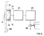
- FIG. 3 shows the schematic structure of a digital precipitation sensor system.
- the sensor system consists of the optical sensor 10, 20, the evaluation unit 30 and the control unit 40, the optical sensor containing the optical unit 10 and the sensor electronics unit 20.
- the optical unit 10 comprises the transmitter unit 11 with a current source and the transmitter element 14, the receiver unit 12 with the receiver element 15 and an oscillating circuit, and the optical path 13 between the transmitter element 14 and the receiver element 15.
- the oscillator circuit filters that signal from the frequency mixture emitted by the transmitter element 14 out that corresponds to its resonance frequency; this signal is amplified and used to feed the transmission element 14.
- the evaluation unit 30, for example a computer or microprocessor, recognizes the different pulse sequences and can trigger corresponding reactions by the control unit 40.
- FIG. 2 shows the time sequences at various points on the circuit diagram in FIG. 1;
- FIG. 2a shows the received signal U E with the through the comparators K1 to K3 predetermined threshold values S1, S2 and S3, in Figure 2b the signals at the output of the comparators K1, K2 and K3 and the clock signal at the output of the clock oscillator OSZ are shown from top to bottom.
- the D / A converter 23 is set to the maximum value when the sensor system is switched on (time t 1) by the first logic stage L 1, so that the value of the D / A Converter predetermined transmission current of the transmission element and thus also the received signal U E at the output of the receiving unit assumes the maximum value ( Figure 2a) and thus exceeds the threshold S 1.
- a pulse train ( Figure 2b), which gradually resets the D / A converter 23 controlled by the second logic stage L 2 and the first counter Z 1 and thus reduces the amplitude of the transmission current.
- the amplitude of the transmit signal is increased until the received signal U E again reaches the switching threshold S1 and the sensor has reached its basic setting (time t4) .
- the further comparator K3 is provided, which provides a large change in the received signal U E (time t5) - falling below the comparator threshold S3 at time t6 - no more output pulses to the first logic level L1. This is recognized and evaluated by the evaluation unit 30 and a faster or stronger reaction of the control unit 40 to the signal change is initiated.
- the transmission current is ramped up to its maximum value and then reduced by the logic level L 3 and the D / A converter 23, as in the switch-on process, and then reduced, as a result of which the sensor quickly reaches its basic setting.
- a precipitation sensor is shown in FIG. 3, which consists of the optical sensor 10 working in the infrared range, the sensor electronics 20 and the microprocessor 30.
- the precipitation sensor is intended to detect the wetting of the windshield 50 of a motor vehicle, for example through a film of moisture or through Impacting raindrops is caused and control the wiper system 40 according to the degree of wetting or the amount of precipitation.
- the precipitation sensor can be used with different types of windshields 50 - white glass, thermal insulation glass, anti-glare glass - which have different optical properties, the control of the windshield wiper system 40 by the microprocessor 30 taking place as a function of the moisture or the degree of wetting of the windshield 50 - from the slow interval wiping with a film of moisture or individual raindrops to the quick permanent wiping with rainstorms or splashing water.
- the precipitation sensor can be activated manually by pressing a switch, which can be displayed optically if necessary; if the activated sensor does not detect any raindrops, a wiping process can be triggered automatically after a specific predefinable time, for example 60 s.
- the optical sensor 10 consists, for example, of an IR transmitter diode 11, a lens system 16 and an IR receiver diode 12, the sensor being fastened to the inside of the windshield 50 and the lenses 16 being at an angle of 45 ° to the pane 50.
- the change in the light reflected on the outside of the windshield within the sensor area 17 - due to the presence of water drops - is detected by the sensor electronics 20 and this change in reflection is evaluated by the microprocessor 30.
- AC voltages are used, the frequency of which is, for example, 50 kHz.
- the sensor delivers an output pulse with a defined width and its frequency depends on the degree of wetting or the number of drops detected on the windshield.
- a fixed threshold value S 1 - for example 700 mV - is specified for all different windshields 50 for the received signal. If individual raindrops hit the windshield 50, the received signal is reduced and the comparator threshold S2 is undershot; since the comparator threshold S3 is not fallen below, slow control of the wipers - for example after an adjustable response time - is specified. With large amounts of water on the windshield - for example splashing water or continuous rain - the received signal is reduced so much that the comparator threshold S3 is not reached. This triggers an immediate actuation of the windscreen wipers; by subsequently initializing the sensor by specifying the basic setting, the sensor system can be addressed again immediately.
- optical sensor system Another possible application of the optical sensor system is to detect bubbles or contaminants in liquids. For example, in the case of colored liquids in pipes with a continuous flow rate, signal changes occur which can be recognized by the sensor in the case of impurities or gas bubbles.
Landscapes
- Engineering & Computer Science (AREA)
- Physics & Mathematics (AREA)
- General Physics & Mathematics (AREA)
- Mechanical Engineering (AREA)
- Automation & Control Theory (AREA)
- Electromagnetism (AREA)
- Life Sciences & Earth Sciences (AREA)
- General Life Sciences & Earth Sciences (AREA)
- Geophysics (AREA)
- Computer Networks & Wireless Communication (AREA)
- Radar, Positioning & Navigation (AREA)
- Remote Sensing (AREA)
- Investigating Or Analysing Materials By Optical Means (AREA)
Applications Claiming Priority (2)
| Application Number | Priority Date | Filing Date | Title |
|---|---|---|---|
| DE4036407 | 1990-11-15 | ||
| DE4036407A DE4036407C2 (de) | 1990-11-15 | 1990-11-15 | Sensorsystem |
Publications (3)
| Publication Number | Publication Date |
|---|---|
| EP0485857A2 true EP0485857A2 (fr) | 1992-05-20 |
| EP0485857A3 EP0485857A3 (fr) | 1992-12-30 |
| EP0485857B1 EP0485857B1 (fr) | 1995-08-30 |
Family
ID=6418322
Family Applications (1)
| Application Number | Title | Priority Date | Filing Date |
|---|---|---|---|
| EP91118808A Expired - Lifetime EP0485857B1 (fr) | 1990-11-15 | 1991-11-05 | Système de senseur et son application |
Country Status (4)
| Country | Link |
|---|---|
| US (1) | US5225669A (fr) |
| EP (1) | EP0485857B1 (fr) |
| JP (1) | JPH04299235A (fr) |
| DE (1) | DE4036407C2 (fr) |
Cited By (7)
| Publication number | Priority date | Publication date | Assignee | Title |
|---|---|---|---|---|
| WO1993013505A1 (fr) * | 1991-12-21 | 1993-07-08 | Richard Hirschmann Gmbh & Co. | Procede et installation de securite |
| WO1994017430A1 (fr) * | 1993-01-25 | 1994-08-04 | Emc Engineering & Marketing Consulting A/S | Procede de reglage d'un trajet de signaux electro-optiques et appareil permettant d'appliquer ce procede |
| EP0891044A1 (fr) * | 1997-07-10 | 1999-01-13 | Sick Ag | Procédé pour la commande d'un dispositif détecteur optoélectrique |
| EP1627785A1 (fr) | 2004-08-20 | 2006-02-22 | Denso Corporation | Système de communication entre dispositifs |
| EP1686026A1 (fr) * | 2005-01-31 | 2006-08-02 | IEE INTERNATIONAL ELECTRONICS & ENGINEERING S.A. | Capteur capacitif différentiel de pluie |
| CN104955732A (zh) * | 2012-08-31 | 2015-09-30 | 福尔康盛瑞士317有限公司 | 用于储存并分发多剂量的固体药物部的储存配给站 |
| CN112612028A (zh) * | 2020-12-28 | 2021-04-06 | 珠海格力电器股份有限公司 | 红外接近感应方法和装置、空调和存储介质 |
Families Citing this family (29)
| Publication number | Priority date | Publication date | Assignee | Title |
|---|---|---|---|---|
| DE4217390C2 (de) * | 1991-06-24 | 1994-06-16 | Kostal Leopold Gmbh & Co Kg | Einrichtung zur Steuerung einer Scheibenwischanlage |
| US5237249A (en) * | 1992-05-26 | 1993-08-17 | Leopold Kostal Gmbh & Co. | Apparatus for controlling a windscreen wiping system |
| DE9301124U1 (de) * | 1993-01-28 | 1993-03-25 | Wolle, Rudi, 5442 Mendig | Feuchtigkeitsmelder als Sicherheitselement in Verbindung mit Scheibenwischeranlagen von Fahrzeugen |
| US5313072A (en) * | 1993-02-16 | 1994-05-17 | Rockwell International Corporation | Optical detector for windshield wiper control |
| KR100302088B1 (ko) * | 1993-07-02 | 2001-12-28 | 게르트 라이메 | 배면방사요소의 변동검지장치 |
| DE4339572A1 (de) * | 1993-11-19 | 1995-05-24 | Gerd Reime | Vorrichtung mit einer Meßanordnung |
| US5726547A (en) * | 1993-07-02 | 1998-03-10 | Reime; Gerd | Windshield wiper arrangement including wiper control system |
| DE4324590C2 (de) * | 1993-07-22 | 1995-06-08 | Leuze Electronic Gmbh & Co | Lichtschrankenanordnung mit geregelter Ansprechempfindlichkeit |
| JPH09503068A (ja) * | 1994-07-15 | 1997-03-25 | バウマー エレクトリック アーゲー | 不要光を抑制する光センサ |
| FR2723448B1 (fr) * | 1994-08-02 | 1996-10-31 | Valeo Electronique | Dispositif de detection d'eau ou analogue sur une glace de vehicule automobile |
| JP3903189B2 (ja) * | 1995-03-07 | 2007-04-11 | マイクロン・テクノロジー・インコーポレーテッド | Dram半導体装置 |
| DE19519485C2 (de) * | 1995-05-27 | 1998-01-29 | Bosch Gmbh Robert | Vorrichtung zum Betreiben eines Scheibenwischers |
| DE19601805C2 (de) * | 1996-01-19 | 2003-02-13 | Bosch Gmbh Robert | Vorrichtung zum Betreiben eines Scheibenwischers |
| DE19601781C2 (de) * | 1996-01-19 | 2001-06-21 | Bosch Gmbh Robert | Vorrichtung zum Betreiben eines Scheibenwischers mit einer automatischen Wischersteuerung |
| DE19606675A1 (de) * | 1996-02-22 | 1997-08-28 | Siemens Ag | Verfahren und Vorrichtung zum Detektieren eines Objekts in einem zu überwachenden Bereich |
| DE19729103A1 (de) * | 1997-07-08 | 1999-01-14 | Bosch Gmbh Robert | Vorrichtung und Verfahren zum Betreiben eines Regensensors |
| EP0926512B1 (fr) * | 1997-12-17 | 2006-03-08 | Inter Company Computer, Engineering, Design Services, in het kort : " Concept Design", naamloze vennootschap | Dispositif de détection de proximité |
| JP2002511568A (ja) * | 1998-04-08 | 2002-04-16 | ローベルト ボツシユ ゲゼルシヤフト ミツト ベシユレンクテル ハフツング | 雨センサ |
| DE19842064A1 (de) * | 1998-09-15 | 2000-03-16 | Bosch Gmbh Robert | Vorrichtung zur automatischen Ansteuerung einer Einrichtung |
| US6078056A (en) * | 1998-12-30 | 2000-06-20 | Libbey-Owens-Ford Co. | Moisture sensor with autobalance control |
| US6091065A (en) * | 1998-12-31 | 2000-07-18 | Libbey-Owens-Ford Co. | Moisture sensor with digital signal processing filtering |
| US6262407B1 (en) | 1998-12-31 | 2001-07-17 | Libbey-Owens-Ford Co. | Moisture sensor with automatic emitter intensity control |
| GB2355523B (en) * | 1999-10-21 | 2004-03-10 | Notetry Ltd | Detection system |
| JP2001180447A (ja) * | 1999-12-28 | 2001-07-03 | Nippon Sheet Glass Co Ltd | 検出装置およびそれを用いたワイパー制御装置 |
| US7050949B2 (en) * | 1999-12-28 | 2006-05-23 | Niles Co., Ltd. | Signal processing method and device |
| JP2004165215A (ja) * | 2002-11-08 | 2004-06-10 | Hosiden Corp | 光電センサ |
| US7896196B2 (en) * | 2007-06-27 | 2011-03-01 | Joseph S. Kanfer | Fluid dispenser having infrared user sensor |
| US20090153860A1 (en) * | 2007-12-17 | 2009-06-18 | Quality Vision International, Inc. | Optical comparator using light- emitting diode light sources |
| EP2265827B1 (fr) * | 2008-03-31 | 2013-04-03 | Parker-Hannifin Corporation | Vanne de prélèvement d'air réacteur automatique pour un système hydraulique fermé |
Family Cites Families (23)
| Publication number | Priority date | Publication date | Assignee | Title |
|---|---|---|---|---|
| JPS5713327A (en) * | 1980-06-27 | 1982-01-23 | Laurel Bank Mach Co Ltd | Optical detector |
| DE3203091C2 (de) * | 1982-01-30 | 1985-06-13 | Vdo Adolf Schindling Ag, 6000 Frankfurt | Einrichtung zum Steuern der Scheibenreinigungsanlage eines Kraftfahrzeugs |
| US4708482A (en) * | 1982-02-22 | 1987-11-24 | Armco Inc. | Method and apparatus for measuring wear in the lining of refractory furnaces |
| DE3314770A1 (de) * | 1983-04-23 | 1984-10-31 | Sidler GmbH & Co, 7400 Tübingen | Einrichtung zum steuern eines scheibenwischermotors |
| DE3409818A1 (de) * | 1984-03-16 | 1985-09-26 | Siemens AG, 1000 Berlin und 8000 München | Optoelektronisches abtastsystem mit automatischem abgleich |
| JPS60252045A (ja) * | 1984-05-28 | 1985-12-12 | Toyota Motor Corp | 車両用オ−トワイパの制御方法 |
| US4680462A (en) * | 1984-12-11 | 1987-07-14 | Baxter Travenol Laboratories, Inc. | Fluid drop detection system |
| EP0191639A3 (fr) * | 1985-02-15 | 1989-07-12 | Toyota Jidosha Kabushiki Kaisha | Appareil et méthode pour commander un essuie-glace |
| US4620141A (en) * | 1985-07-03 | 1986-10-28 | Vericom Corp. | Rain-controlled windshield wipers |
| DE3538553A1 (de) * | 1985-10-30 | 1987-05-07 | Philips Patentverwaltung | Anordnung zur steuerung einer scheibenwischanlage |
| JPS62179637A (ja) * | 1986-02-01 | 1987-08-06 | Fujitsu Ten Ltd | バッテリ式産業車両の走行制御装置 |
| DE3619209A1 (de) * | 1986-06-07 | 1987-12-10 | Bosch Gmbh Robert | Vorrichtung zum optischen erfassen von fremdkoerpern |
| US4836682A (en) * | 1986-07-02 | 1989-06-06 | E. I. Dupont De Nemours And Company | Method and apparatus for calibrating optical sensors |
| KR910001269B1 (ko) * | 1986-07-11 | 1991-02-26 | 로우렐 뱅크 머시인 가부시끼가이샤 | 광센서 조정용 장치 |
| DE3627074A1 (de) * | 1986-08-09 | 1988-02-11 | Bosch Gmbh Robert | Einrichtung zur beobachtung und auswertung von verbrennungsvorgaengen in brennkraftmaschinen |
| DE3715798A1 (de) * | 1987-05-12 | 1988-01-07 | Erich Ing Grad Huber | Opto-elektronische einrichtung zum erkennen von verschmutzung transparenter schutzscheiben und ausloesen der reinigungsmassnahmen |
| IT212332Z2 (it) * | 1987-07-31 | 1989-07-04 | Veglia Borletti Srl | Dispositivo sensore della presenza di gocce d acqua su un cristallo di un veicolo e apparecchiatura dicomando di un tergicristallo provvista del detto dispositivo |
| IT212441Z2 (it) * | 1987-07-31 | 1989-07-04 | Veglia Borletti Srl | Dispositivo sensore della presenza di gocce di acqua su un cristallo di un veicolo e apparecchiatura dicomando di un tergicristallo provvista del detto dispositivo |
| DE3733762A1 (de) * | 1987-10-06 | 1989-04-20 | Karl Gerhard | Scheibenverschmutzungsmelder |
| BG47531A1 (en) * | 1987-12-15 | 1990-08-15 | Vissh Inst Khranitelno Vkusova | Device for automatic sorting of fruits, vegetables and tuberiferous plants according to their quality |
| DE3806881A1 (de) * | 1988-03-03 | 1989-09-07 | Kostal Leopold Gmbh & Co Kg | Sensoreinrichtung |
| JPH01257227A (ja) * | 1988-04-06 | 1989-10-13 | Chinon Ind Inc | 光検知装置 |
| JPH0524071Y2 (fr) * | 1988-08-11 | 1993-06-18 |
-
1990
- 1990-11-15 DE DE4036407A patent/DE4036407C2/de not_active Expired - Fee Related
-
1991
- 1991-10-08 US US07/772,940 patent/US5225669A/en not_active Expired - Fee Related
- 1991-11-05 EP EP91118808A patent/EP0485857B1/fr not_active Expired - Lifetime
- 1991-11-14 JP JP3298704A patent/JPH04299235A/ja active Pending
Cited By (16)
| Publication number | Priority date | Publication date | Assignee | Title |
|---|---|---|---|---|
| WO1993013505A1 (fr) * | 1991-12-21 | 1993-07-08 | Richard Hirschmann Gmbh & Co. | Procede et installation de securite |
| WO1994017430A1 (fr) * | 1993-01-25 | 1994-08-04 | Emc Engineering & Marketing Consulting A/S | Procede de reglage d'un trajet de signaux electro-optiques et appareil permettant d'appliquer ce procede |
| EP0891044A1 (fr) * | 1997-07-10 | 1999-01-13 | Sick Ag | Procédé pour la commande d'un dispositif détecteur optoélectrique |
| US6121605A (en) * | 1997-07-10 | 2000-09-19 | Sick Ag | Method for the operation of an optoelectronic sensor |
| EP1627785A1 (fr) | 2004-08-20 | 2006-02-22 | Denso Corporation | Système de communication entre dispositifs |
| CN100409267C (zh) * | 2004-08-20 | 2008-08-06 | 株式会社电装 | 设备间通信系统 |
| EP1686026A1 (fr) * | 2005-01-31 | 2006-08-02 | IEE INTERNATIONAL ELECTRONICS & ENGINEERING S.A. | Capteur capacitif différentiel de pluie |
| WO2006079621A1 (fr) * | 2005-01-31 | 2006-08-03 | Iee International Electronics & Engineering S.A. | Detecteur de pluie capacitif differentiel |
| CN104955732A (zh) * | 2012-08-31 | 2015-09-30 | 福尔康盛瑞士317有限公司 | 用于储存并分发多剂量的固体药物部的储存配给站 |
| US10099809B2 (en) | 2012-08-31 | 2018-10-16 | Carefusion Switzerland 317 Sàrl | Storage and dosing station for storage and dispensing dosed quantities of solid drug portions |
| US10800566B2 (en) | 2012-08-31 | 2020-10-13 | Carefusion Switserland 317 Sàrl | Storage and dosing station for storage and dispensing dosed quantities of solid drug portions |
| US11572213B2 (en) | 2012-08-31 | 2023-02-07 | Carefusion Switzerland 317 Sàrl | Storage and dosing station for storage and dispensing dosed quantities of solid drug portions |
| US11772837B2 (en) | 2012-08-31 | 2023-10-03 | Carefusion Switzerland 317 Sàrl | Storage and dosing station for storage and dispensing dosed quantities of solid drug portions |
| US12084217B2 (en) | 2012-08-31 | 2024-09-10 | Carefusion Switzerland 317 Sàrl | Storage and dosing station for storage and dispensing dosed quantities of solid drug portions |
| CN112612028A (zh) * | 2020-12-28 | 2021-04-06 | 珠海格力电器股份有限公司 | 红外接近感应方法和装置、空调和存储介质 |
| CN112612028B (zh) * | 2020-12-28 | 2024-01-23 | 珠海格力电器股份有限公司 | 红外接近感应方法和装置、空调和存储介质 |
Also Published As
| Publication number | Publication date |
|---|---|
| DE4036407A1 (de) | 1992-05-21 |
| EP0485857A3 (fr) | 1992-12-30 |
| JPH04299235A (ja) | 1992-10-22 |
| US5225669A (en) | 1993-07-06 |
| EP0485857B1 (fr) | 1995-08-30 |
| DE4036407C2 (de) | 1994-06-01 |
Similar Documents
| Publication | Publication Date | Title |
|---|---|---|
| EP0485857B1 (fr) | Système de senseur et son application | |
| EP0871579B2 (fr) | Dispositif de commande pour un capteur optique | |
| EP1468401B1 (fr) | Procede et dispositif de detection d'obstacles a la visibilite dans le cas de systemes de detection d'images | |
| EP0482006B1 (fr) | Detecteur d'impuretes pour vitres d'automobiles | |
| EP0682611B1 (fr) | Dispositif pour l'utilisation d'un detecteur de pluie | |
| DE3722510C2 (fr) | ||
| EP2558336B1 (fr) | Procédé et dispositif d'assistance au conducteur lors de la conduite d'un véhicule consistant à détecter une visibilité réduite due aux conditions atmosphériques | |
| EP0112498A2 (fr) | Appareil pour le nettoyage automatique des fenêtres | |
| DE19614100A1 (de) | Vorrichtung zur Ermittlung des Zustandes eines Wischerblattes | |
| EP0705186B1 (fr) | Dispositif de commande d'un systeme d'essuie-glace | |
| EP0537471A1 (fr) | Procédé pour adapter la sensibilité de réaction d'un système détecteur de pluie à des conditions ambiantes et système détecteur avec un détecteur de pluie | |
| DE19526249A1 (de) | Vorrichtung zur Erfassung von Wasser oder dergleichen auf einer Fensterscheibe eines Kraftfahrzeuges | |
| EP0547337A1 (fr) | Dispositif de commande d'un système d'essuie-glaces | |
| DE4324590C2 (de) | Lichtschrankenanordnung mit geregelter Ansprechempfindlichkeit | |
| DE19801745A1 (de) | Vorrichtung zur Überwachung des Zustands einer Fensterscheibe | |
| DE19729103A1 (de) | Vorrichtung und Verfahren zum Betreiben eines Regensensors | |
| DE4228112C1 (en) | Object detection arrangement - contains light source and receiver, comparator with comparison voltages controlled by micro-controller | |
| DE4312590A1 (de) | Optoelektronische Einrichtung für Klarsichtscheiben zum Erkennen der Benetzung und Verschmutzungen und zur automatischen Betätigung von Warn- und/oder Reinigungsanlagen | |
| EP1135285B1 (fr) | Dispositif permettant de detecter des particules sur un pare-brise | |
| DE2101319A1 (de) | Verfahren zur automatischen Steuerung einer Scheibenreinigungsanlage | |
| DE4229491A1 (de) | Vorrichtung zur steuerung einer scheibenwischeranlage fuer kraftfahrzeuge | |
| EP2209675B1 (fr) | Procede pour faire fonctionner un detecteur de pluie, en particulier pour des vehicules automobiles | |
| DE4217390C2 (de) | Einrichtung zur Steuerung einer Scheibenwischanlage | |
| DE19519471C2 (de) | Vorrichtung zum Betreiben eines Scheibenwischers | |
| DE19822180B4 (de) | Vorrichtung zur Ansteuerung einer Scheibenwischanlage, insbesondere für Kraftfahrzeuge |
Legal Events
| Date | Code | Title | Description |
|---|---|---|---|
| PUAI | Public reference made under article 153(3) epc to a published international application that has entered the european phase |
Free format text: ORIGINAL CODE: 0009012 |
|
| AK | Designated contracting states |
Kind code of ref document: A2 Designated state(s): FR GB IT SE |
|
| PUAL | Search report despatched |
Free format text: ORIGINAL CODE: 0009013 |
|
| AK | Designated contracting states |
Kind code of ref document: A3 Designated state(s): FR GB IT SE |
|
| RAP1 | Party data changed (applicant data changed or rights of an application transferred) |
Owner name: TEMIC TELEFUNKEN MICROELECTRONIC GMBH |
|
| 17P | Request for examination filed |
Effective date: 19930319 |
|
| 17Q | First examination report despatched |
Effective date: 19940621 |
|
| GRAA | (expected) grant |
Free format text: ORIGINAL CODE: 0009210 |
|
| AK | Designated contracting states |
Kind code of ref document: B1 Designated state(s): FR GB IT SE |
|
| GBT | Gb: translation of ep patent filed (gb section 77(6)(a)/1977) |
Effective date: 19950829 |
|
| ITF | It: translation for a ep patent filed | ||
| PGFP | Annual fee paid to national office [announced via postgrant information from national office to epo] |
Ref country code: GB Payment date: 19951018 Year of fee payment: 5 |
|
| PGFP | Annual fee paid to national office [announced via postgrant information from national office to epo] |
Ref country code: FR Payment date: 19951107 Year of fee payment: 5 |
|
| PGFP | Annual fee paid to national office [announced via postgrant information from national office to epo] |
Ref country code: SE Payment date: 19951114 Year of fee payment: 5 |
|
| ET | Fr: translation filed | ||
| PLBE | No opposition filed within time limit |
Free format text: ORIGINAL CODE: 0009261 |
|
| STAA | Information on the status of an ep patent application or granted ep patent |
Free format text: STATUS: NO OPPOSITION FILED WITHIN TIME LIMIT |
|
| 26N | No opposition filed | ||
| PG25 | Lapsed in a contracting state [announced via postgrant information from national office to epo] |
Ref country code: GB Effective date: 19961105 |
|
| PG25 | Lapsed in a contracting state [announced via postgrant information from national office to epo] |
Ref country code: SE Effective date: 19961106 |
|
| GBPC | Gb: european patent ceased through non-payment of renewal fee |
Effective date: 19961105 |
|
| PG25 | Lapsed in a contracting state [announced via postgrant information from national office to epo] |
Ref country code: FR Effective date: 19970731 |
|
| EUG | Se: european patent has lapsed |
Ref document number: 91118808.4 |
|
| REG | Reference to a national code |
Ref country code: FR Ref legal event code: ST |
|
| PG25 | Lapsed in a contracting state [announced via postgrant information from national office to epo] |
Ref country code: IT Free format text: LAPSE BECAUSE OF NON-PAYMENT OF DUE FEES Effective date: 20051105 |