EP0485943B1 - Knöchelpelotte, Pelotteneinheit und diese enthaltende Knöchelbandage - Google Patents
Knöchelpelotte, Pelotteneinheit und diese enthaltende Knöchelbandage Download PDFInfo
- Publication number
- EP0485943B1 EP0485943B1 EP91119250A EP91119250A EP0485943B1 EP 0485943 B1 EP0485943 B1 EP 0485943B1 EP 91119250 A EP91119250 A EP 91119250A EP 91119250 A EP91119250 A EP 91119250A EP 0485943 B1 EP0485943 B1 EP 0485943B1
- Authority
- EP
- European Patent Office
- Prior art keywords
- ankle
- area
- profiled
- inlay
- pad
- Prior art date
- Legal status (The legal status is an assumption and is not a legal conclusion. Google has not performed a legal analysis and makes no representation as to the accuracy of the status listed.)
- Expired - Lifetime
Links
- 210000003423 ankle Anatomy 0.000 title claims abstract description 69
- 210000002683 foot Anatomy 0.000 claims abstract description 35
- 210000001361 achilles tendon Anatomy 0.000 claims abstract description 9
- 239000000463 material Substances 0.000 claims description 18
- 229920001296 polysiloxane Polymers 0.000 claims description 17
- 210000000544 articulatio talocruralis Anatomy 0.000 claims description 15
- 239000003190 viscoelastic substance Substances 0.000 claims description 7
- 230000006835 compression Effects 0.000 claims description 4
- 238000007906 compression Methods 0.000 claims description 4
- 230000003247 decreasing effect Effects 0.000 claims description 3
- 230000006641 stabilisation Effects 0.000 claims description 3
- 238000011105 stabilization Methods 0.000 claims description 3
- 238000003825 pressing Methods 0.000 claims description 2
- 238000009825 accumulation Methods 0.000 claims 2
- 230000035508 accumulation Effects 0.000 claims 2
- 210000004744 fore-foot Anatomy 0.000 claims 1
- 230000003014 reinforcing effect Effects 0.000 claims 1
- 210000004233 talus Anatomy 0.000 abstract 1
- 210000000988 bone and bone Anatomy 0.000 description 4
- 230000000087 stabilizing effect Effects 0.000 description 3
- 206010030113 Oedema Diseases 0.000 description 2
- 230000000694 effects Effects 0.000 description 2
- 210000004872 soft tissue Anatomy 0.000 description 2
- 206010018852 Haematoma Diseases 0.000 description 1
- 238000010521 absorption reaction Methods 0.000 description 1
- 210000003484 anatomy Anatomy 0.000 description 1
- 238000001266 bandaging Methods 0.000 description 1
- 230000017531 blood circulation Effects 0.000 description 1
- 239000000872 buffer Substances 0.000 description 1
- 239000013013 elastic material Substances 0.000 description 1
- 230000009969 flowable effect Effects 0.000 description 1
- 239000003292 glue Substances 0.000 description 1
- 210000000474 heel Anatomy 0.000 description 1
- 210000000281 joint capsule Anatomy 0.000 description 1
- 210000000452 mid-foot Anatomy 0.000 description 1
- 230000002093 peripheral effect Effects 0.000 description 1
- 239000011505 plaster Substances 0.000 description 1
- 230000002787 reinforcement Effects 0.000 description 1
- 238000009877 rendering Methods 0.000 description 1
- 239000012858 resilient material Substances 0.000 description 1
- 230000000284 resting effect Effects 0.000 description 1
- 230000001020 rhythmical effect Effects 0.000 description 1
- 238000005096 rolling process Methods 0.000 description 1
- 239000003351 stiffener Substances 0.000 description 1
- 230000008961 swelling Effects 0.000 description 1
- 210000002435 tendon Anatomy 0.000 description 1
- 230000001225 therapeutic effect Effects 0.000 description 1
Images


Classifications
-
- A—HUMAN NECESSITIES
- A61—MEDICAL OR VETERINARY SCIENCE; HYGIENE
- A61F—FILTERS IMPLANTABLE INTO BLOOD VESSELS; PROSTHESES; DEVICES PROVIDING PATENCY TO, OR PREVENTING COLLAPSING OF, TUBULAR STRUCTURES OF THE BODY, e.g. STENTS; ORTHOPAEDIC, NURSING OR CONTRACEPTIVE DEVICES; FOMENTATION; TREATMENT OR PROTECTION OF EYES OR EARS; BANDAGES, DRESSINGS OR ABSORBENT PADS; FIRST-AID KITS
- A61F5/00—Orthopaedic methods or devices for non-surgical treatment of bones or joints; Nursing devices ; Anti-rape devices
- A61F5/01—Orthopaedic devices, e.g. long-term immobilising or pressure directing devices for treating broken or deformed bones such as splints, casts or braces
- A61F5/0102—Orthopaedic devices, e.g. long-term immobilising or pressure directing devices for treating broken or deformed bones such as splints, casts or braces specially adapted for correcting deformities of the limbs or for supporting them; Ortheses, e.g. with articulations
- A61F5/0104—Orthopaedic devices, e.g. long-term immobilising or pressure directing devices for treating broken or deformed bones such as splints, casts or braces specially adapted for correcting deformities of the limbs or for supporting them; Ortheses, e.g. with articulations without articulation
- A61F5/0111—Orthopaedic devices, e.g. long-term immobilising or pressure directing devices for treating broken or deformed bones such as splints, casts or braces specially adapted for correcting deformities of the limbs or for supporting them; Ortheses, e.g. with articulations without articulation for the feet or ankles
Definitions
- the invention initially relates to a viscoelastic ankle pad with the features of the preamble of claim 1.
- Such pads formed by a viscoelastic profile insert are known as a component of ankle supports, for example. They are designed to apply an intermittent compression pressure to the soft tissues of the joint. For this purpose, they are designed so that they only derive the compression pressure from the ankle protrusions on both sides in the ankle furrows, i.e. only in the peripheral relief area of the ankle, and exert a rhythmic massage effect on soft tissues, joint capsules and tendon boxes.
- the constantly massaging effect of the silicone buffers is intended to promote blood circulation and rapid swelling, pain relief and functional improvement for the rapid absorption of edema and hematoma.
- a medically oriented insert is known from EP-A-0 350 517, in which two shafts with pads made of a resilient material are attached to the side of a shoe insole.
- the shafts are connected to the sole by a hem.
- the pads are disc-shaped and designed with L-shaped pads. The pads grip the ankle of the ankle.
- the object of the invention is to further develop such a pad for an even broader range of indications.
- This object is achieved by the characterizing features of claim 1.
- this pad When used on both sides, this pad is suitable for at least partially stabilizing the ankle joint and in some cases even rendering plaster immobilization superfluous. It is capable of decongesting and thus decompressing the inner ankle area (tarsal tunnel under the ligamentum laciniatum).
- the pad does not have to be part of an ankle brace. It can also be used for bandages, for example. As a rule, a pad is placed on both sides of the foot, regardless of whether this is done with a bandage or with a prefabricated, elastic bandage.
- the pad On one side, the pad has a flat outer surface on the outside of the foot and a slightly convex, sloping wall with decreasing wall thickness towards the edges, facing the foot in the worn state.
- the respective wall thickness is adapted to the relief structures, namely the anatomy of the foot, especially in the edge region.
- the outline of a pad to be placed on the ankle area of a foot from the left and from the right side is mirror-inverted, with the only difference that the convex side faces the foot.
- the pad For at least partial coverage of the heel area as well, the pad has a tongue-like protruding, clearly recognizable projection.
- the pads according to the invention Due to the design of the pads according to the invention, their viscoelastic material flows more or less into the ankle area and / or into the Achilles tendon area and / or into the heel area, depending on the relief shape of the foot and the pressure exerted, for example, by a bandage or a shoe lacing and / or into the sole area and there exerts pressure on an existing edema. This is possible due to the significantly larger surface area of the pelotte according to the invention compared to known such pelotte.
- the pad according to the invention also extends, for example, into the particularly pressure-sensitive ankle area, it is furthermore expedient to make it from silicone materials of different consistency to produce that, for example, a relatively soft silicone material is used in the ankle overlap region and a comparatively hard silicone material in the ankle groove or relief region.
- Another feature of the invention provides for a profile insert made of a comparatively hard, less elastic material in the pad for stabilization in the bone groove or relief area. It is designed in such a way that, when the pad is in contact, it lies in the bone furrow area of the foot, that is to say it surrounds the ankle area from behind and below.
- This stiffening consists of an L-shaped surface part, in particular of a PVC. This material makes it possible to bond or glue to the silicone material of the pad.
- the stabilizing insert serves to immobilize the ankle and ensures lateral stabilization of the ankle joint. Because it lies in the area of the ankle, there is already a mass of the flowable silicone material there. The flow of the silicone material is dampened by the insert of the stiffener. This favors the application of contact pressure on the part of a bandage, a bandage or a lace. This in turn ensures a constant contact pressure, which - as desired - is also effective in the ankle, Achilles tendon, heel and sole areas.
- Another feature of the invention connects two ankle pads in the region of their edges on the sole of the foot by a thin-walled web.
- This web expediently extends over at least one third of the length of the pad edge on the sole of the foot.
- This configuration has several advantages. On the one hand, it binds the two pads that usually come into contact with one another, so that there is greater security against loss. It also makes it easier to put on the foot when bandaging.
- the connecting web When inserted in an anatomically elongated two-pull bandage in the form of an elastic knitted tube, the connecting web has the advantage that the same bandage with the pads can be used in the same way for use on the left as on the right foot, while in such conventional ankle bandages because of the different Elevation of the inner and outer ankles on the human foot, separate left and right ankle bandages were required.
- the thin-walled, elastic connecting web is also able to dampen rolling and treading as well as correcting the rearfoot and midfoot position by applying pressure to the sole of the foot.
- This connecting bridge means a further therapeutic enrichment.
- the use of this connecting web between the two pads is not necessarily bound to the pad shape according to claim 1. Rather, this connecting web can also be used advantageously in conventional ankle pads that fill only the ankle groove in the applied state.
- the viscoelastic profile insert for generating an intermittent compression pressure in the ankle area is characterized by a large-area design such that, in addition to the bone furrow or the relief area between the ankle on the one hand and the Achilles tendon, heel and sole area, on the other hand Ankle area 1 of the foot itself and / or its Achilles tendon area 2, and / or its heel area 3 and / or its sole area 4 at least partially covers.
- the pad has on one side a flat outer side 5 on the foot side in the worn state.
- the pad In its area partially covering the heel area 3 of the foot, the pad has a tongue-like projection 7.
- the pad is made of differently consistent silicone materials.
- a comparatively soft silicone material shown in dotted lines in FIG. 1 is used, which is characterized by an easier sliding flowability, but nevertheless exerts sufficient pressure on the ankle area, but in this particularly pressure-sensitive area because it protrudes a lighter area Balance creates.
- a comparatively harder silicone material is used, where mainly the bone groove area of the foot is present when it is worn.
- a special feature is a comparatively less elastic profile insert 9 for stabilizing the relief area of the foot.
- the profile insert essentially has an L-shape for inserting in said Ankle groove or relief area. It is a thin-walled, flat molded body and consists of a PVC.
- the silicone material of the pad is an addition silion.
- a further peculiarity consists in the joining together of two pelottes intended for bearing against the same foot to form a pelotte unit in that their edges 10 on the sole of the foot are connected to one another by a thin-walled web 11 made of the silicone material.
- the web 11 extends over at least one third of the length of the pad edges 10 on the sole of the foot.
- Two pads or a pad unit of the type described above consisting of two pads can be components of an ankle brace made of an anatomically knitted two-pull brace. In the same way, however, it is possible to make them part of an ankle bandage, which is designed in the manner of a lace-up shaft that is also pulled up over the ankle.
Landscapes
- Health & Medical Sciences (AREA)
- Nursing (AREA)
- Orthopedic Medicine & Surgery (AREA)
- Engineering & Computer Science (AREA)
- Biomedical Technology (AREA)
- Heart & Thoracic Surgery (AREA)
- Vascular Medicine (AREA)
- Life Sciences & Earth Sciences (AREA)
- Animal Behavior & Ethology (AREA)
- General Health & Medical Sciences (AREA)
- Public Health (AREA)
- Veterinary Medicine (AREA)
- Orthopedics, Nursing, And Contraception (AREA)
- Prostheses (AREA)
- Professional, Industrial, Or Sporting Protective Garments (AREA)
Description
- Die Erfindung betrifft zunächst eine viskoelastische Knöchelpelotte mit den Merkmalen des Oberbegriffs des Anspruches 1.
- Derartige durch eine viskoelastische Profileinlage gebildete Pelotten sind als Bestandteil beispielsweise von Fußgelenkbandagen bekannt. Sie sind dazu bestimmt, einen intermittierenden Kompressionsdruck gezielt auf die Gelenkweichteile auszuüben. Dazu sind sie so ausgestaltet, daß sie nur in den Knöchelfurchen, also nur im peripheren Reliefbereich des Fußknöchels beidseitig den Kompressionsdruck von den Knöchelvorsprüngen ableiten und eine rhythmische Massagewirkung auf Weichteile, Gelenkkapseln und Sehnenlogen ausüben. Die ständig massierende Wirkung der Silikonpuffer soll zur raschen Resorption von Ödemen und Hämatomen die Durchblutung fördern sowie ein rasches Abschwellen, Schmerzlinderung und Funktionsverbesserung bewirken.
- Aus der EP-A-0 350 517 ist eine medizinisch orientierte Einlage bekannt, bei der seitlich einer Schuhinnensohle zwei Schäfte mit Pelotten aus einem formelastischen Werkstoff angebracht sind. Die Schäfte sind über je einen Saum mit der Sohle verbunden. Die Pelotten sind scheiben förmig und mit L-förmigen Polstern ausgestaltet. Die Polster umgreifen den Knöchel des Sprunggelenks.
- Der Erfindung liegt die Aufgabe zugrunde, eine derartige Pelotte für einen noch breiteren Indikationsbereich weiterzuentwickeln. Diese Aufgabe wird durch die Kennzeichnungsmerkmale des Anspruches 1 gelöst. Diese Pelotte ist bei beidseitiger Anwendung dazu geeignet, das Sprunggelenk zumindest teilweise zu stabilisieren und dabei teilweise sogar eine Gipsruhigstellung überflüssig zu machen. Sie ist in der Lage, entstauend und damit dekomprimierend am Innenknöchelbereich (Tarsaltunnel unter dem Ligamentum laciniatum) zu wirken.
- Die Pelotte muß nicht Bestandteil einer Sprunggelenkbandage sein. Sie kann beispielsweise auch bei Bandagierungen angewendet werden. In der Regel wird beidseitig am Fuß je eine Pelotte angelegt, gleichgültig ob dies mit einer Bandagierung oder durch eine vorgefertigte, elastische Bandage erfolgt.
- Die Pelotte weist einseitig eine ebene, im Tragezustand fußabseitige Außenseite und eine leicht konvex gewölbte, mit stetig geringer werdender Wandstärke zu den Rändern hin abfallende, im Tragezustand dem Fuß zugewandte Innenseite auf. Dabei ist die jeweilige Wandstärke gerade im Randbereich den Reliefstrukturen, nämlich der Anatomie des Fußes angepaßt. Die Umrißform einer von der linken und einer von der rechten Seite her an den Knöchelbereich eines Fußes anzulegenden Pelotte ist spiegelbildich gleich, nur mit dem Unterschied, daß jeweils die Konvexseite dem Fuß zugewandt ist. Zur wenigstens partiellen Überdeckung auch des Fersenbereiches weist die Pelotte eine zungenartig vorstehende, deutlich erkennbare Ausladung auf.
- Durch die erfindungsgemäße Gestaltung der Pelotten fließt deren viskoelastischer Werkstoff je nach Reliefform des Fußes sowie je nach dem beispielsweise von einer Bandagierung oder auch von einer Schuhschnürung ausgeübten Druck mehr oder weniger auch in die den Knöchelbereich und/oder in den Achillessehnenbereich und/oder in den Fersenbereich und/oder in den Sohlenbereich hinein und übt dort Druck auf ein vorhandenes Ödem aus. Dies ist durch die gegenüber bekannten derartigen Pelotten deutlich größere Flächenerstreckung der erfindungsgemäßen Pelotte möglich.
- Weil sich die erfindungsgemäße Pelotte beispielsweise auch in den besonders druckempfindlichen Knöchelbereich hinein erstreckt, ist es weiterhin zweckmäßig, sie aus unterschiedlich konsistenten Silikonwerkstoffen derart herzustellen, daß beispielsweise im Knöchelüberdeckungsbereich ein relativ weicher und im Knöchelfurchen- oder Reliefbereich ein vergleichsweise harter Silikonwerkstoff verwendet wird.
- Ein weiteres Erfindungsmerkmal sieht in der Pelotte eine Profileinlage aus einem vergleichsweise harten, wenig elastischen Werkstoff zur Stabilisierung im Knochenfurchen- bzw. Reliefbereich vor. Sie ist so gestaltet, daß sie im Anlagezustand der Pelotte im Knochenfurchenbereich des Fußes einliegt, also den Knöchelbereich von hinten und unten gewissermaßen umgibt. Diese Versteifung besteht aus einem L-förmig gestalteten Flächenteil, insbesondere aus einem PVC. Durch diesen Werkstoff ist eine Bindung bzw. Verklebung mit dem Silikonwerkstoff der Pelotte möglich. Die stabilisierende Einlage dient zur Ruhigstellung des Sprunggelenkes und gewährleistet eine Seitenstabilisierung des Knöchelgelenkes. Dadurch, daß sie im Knöchelfurchenbereich einliegt, ist dort von Hause aus ohnehin eine Massierung des fließfähigen Silikonwerkstoffes vorhanden. Durch die Einlage der Versteifung wird die Fließfähigkeit des Silikonwerkstoffes gedämpft. Dadurch wird die Ausübung eines Anpreßdruckes seitens einer Bandage, einer Bandagierung oder eines Schnürschaftes begünstigt. Das wiederum sorgt für einen großflächig gleichbleibenden Anpreßdruck, der - wie gewünscht - auch wirksam ist im Knöchel-, Achillessehnen-, Fersen- und Fußsohlenbereich.
- Die Verwendung einer derartigen, L-förmigen, im Tragezustand in der Knöchelfurche einliegenden Versteifungseinlage ist auch bei einer Pelotte herkömmlicher Umrißform vorteilhaft, die mit ihrem viskoelastischen Werkstoff nur innerhalb der Knöchelfurche bzw. des Reliefbereiches des Fußes einliegt.
- Als Pelottenwerkstoff ist vorteilhaft ein Additions-Silikon verwendet.
- Durch ein weiteres Erfindungsmerkmal sind zwei Sprunggelenkpelotten im Bereich ihrer fußsohlenseitigen Kanten durch einen dünnwandigen Steg miteinander verbunden. Dieser Steg erstreckt sich zweckmäßig über mindestens ein Drittel der Länge der fußsohlenseitigen Pelottenkante. Diese Ausgestaltung hat mehrere Vorteile. Zum einen bindet sie beide üblicherweise gemeinsam zur Anlage gelangenden Pelotten aneinander, so daß eine höhere Verliersicherheit gegeben ist. Darüber hinaus erleichtert sie das Anlegen am Fuß bei der Bandagierung. Bei der Einlage in einer anatomisch formgestreckten Zweizugbandage in Form gewissermaßen eines elastischen Strickschlauches hat der Verbindungssteg den Vorteil, daß dieselbe Bandage mit den Pelotten in gleicher Weise für eine Verwendung am linken wie am rechten Fuß in Betracht kommt, während bei solchen herkömmlichen Knöchelbandagen wegen der unterschiedlichen Höhenlage des Innen- und des Außenknöchels am menschlichen Fuß jeweils gesondert linke und rechte Knöchelbandagen erforderlich waren. Der dünnwandige, elastische Verbindungssteg vermag auch durch die Beaufschlagung der Fußsohle eine Abroll- und Auftrittdämpfung sowie eine Korrektur von Rückfuß- und Mittelfußstellung auszuüben. Damit bedeutet dieser Verbindungssteg eine weitere therapeutische Bereicherung. Auch die Anwendung dieses Verbindungssteges zwischen beiden Pelotten ist nicht zwangsläufig an die Pelottenform gemäß Anspruch 1 gebunden. Vielmehr kann dieser Verbindungssteg auch vorteilhaft bei herkömmlichen, im Anlegezustand nur die Knöchelfurche ausfüllenden Sprunggelenkpelotten verwendet werden.
- Die Erfindung wird anhand von in den Figuren dargestellten Ausführungsbeispielen näher erläutert. Es zeigen:
- Fig. 1
- eine schematische Fußdarstellung mit angelegter Pelotte nach der Erfindung;
- Fig. 2
- eine Ansicht der Fußrückseite mit beidseitig anliegenden Pelotten;
- Fig. 3
- in gemeinsamer Perspektivstellung zwei erfindungsgemäß ausgestaltete Pelotten mit entsprechend der beiderseitigen Anlagestellung am Fuß einander zugewandten Konvexseiten;
- Fig. 4
- die Seitenansicht einer Pelotte mit Schnittdarstellungen aa-aa, bb-bb und cc-cc in unterschiedlichen Schnittrichtungen und mit jeweils einmal linker und einmal rechter Konvexseite;
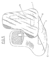
- Fig. 5
- zwei Pelotten mit im Bereich ihrer fußsohlenseitigen Randkanten angeordnetem, dünnwandigem Verbindungssteg;
- Fig. 5a
- eine Pelotteneinheit analog Fig. 5 jedoch mit einer abgewandelten Umrißform der Pelotten;
- Fig. 6
- eine Draufsicht auf die Pelotteneinheit entsprechend Pfeil VI in Fig. 5a mit in die Ebene des Verbindungssteges auseinandergeklappten Pelotten;
- Fig. 7
- die Ansicht einer nach Art eines Schuhschaftes schnürbaren Bandage mit - von außen nicht erkennbar - auf der Innenseite vorliegender Applikation von Pelotten gemäß Fig. 1 - 6.
- Die viskoelastische Profileinlage zur Erzeugung eines intermittierenden Kompressionsdruckes im Sprunggelenkbereich, nämlich die Knöchelpelotte, ist gekennzeichnet durch eine großflächige Ausbildung derart, daß sie neben dem Knochenfurchen- bzw. neben dem Reliefbereich zwischen Knöchel einerseits und Achillessehnen-, Fersen-, und Fußsohlenbereich andererseits auch noch den Knöchelbereich 1 des Fußes selbst und/oder dessen Achillessehnenbereich 2, und/oder dessen Fersenbereich 3 und/oder dessen Fußsohlenbereich 4 wenigstens partiell abdeckt. Dazu weist die Pelotte einseitig eine ebene, im Tragezustand fußabseitige Außenseite 5 auf. Anderseitig ist eine leicht konvex gewölbte, mit stetig geringer werdender Wandstärke zu den Rändern hin abfallende und im Tragezustand dem Fuß zugewandte Innenseite 6 vorhanden. In ihrem den Fersenbereich 3 des Fußes partiell abdeckenden Bereich weist die Pelotte eine zungenartig vorstehende Ausladung 7 auf.
- Die Pelotte ist aus unterschiedlich konsistenten Silikonwerkstoffen gebildet. Im Knöchelbereich 1 ist beispielsweise ein in Fig. 1 punktiert dargestellter, vergleichsweise weicher Silkonwerkstoff verwendet, der sich durch eine leichtere Gleit-Fließbarkeit auszeichnet, indessen doch einen hinreichenden Druck auf den Knöchelbereich ausübt, jedoch in diesem besonders druckempfindlichen, weil weit vorstehenden Bereich einen leichteren Ausgleich schafft. Im übrigen, in Fig. 1 schraffiert dargestellten Pelottenbereich 8 kommt ein vergleichsweise härterer Silikonwerkstoff zur Anwendung, wo im Tragezustand hauptsächlich der Knochenfurchenbereich des Fußes vorhanden ist.
- Eine Besonderheit ist eine vergleichsweise wenig elastische Profileinlage 9 zur Stabilisierung des Reliefbereiches des Fußes. Die Profileinlage weist im wesentlichen eine L-Form zur Einlage im besagten Knöchelfurchen- oder Reliefbereich auf. Sie ist ein dünnwandiger, ebener Formkörper und besteht aus einem PVC. Der Silikonwerkstoff der Pelotte ist ein Additions-Silion.
- Eine weitere Besonderheit besteht in der Zusammenfügung zweier zur Anlage am selben Fuß bestimmter Pelotten zu einer Pelotteneinheit dadurch, daß ihre fußsohlenseitigen Kanten 10 durch einen dünnwandigen Steg 11 aus dem Silikonwerkstoff miteinander verbunden sind. Der Steg 11 erstreckt sich über mindestens ein Drittel der Länge der fußsohlenseitigen Pelottenkanten 10.
- Zwei Pelotten oder eine aus zwei Pelotten bestehende Pelotteneinheit der vorstehend beschriebenen Art können Bestandteile einer Knöchelbandage aus einer auch anatomisch formgestrickten Zweizugbandage sein. Es ist indessen in gleicher Weise möglich, sie zum Bestandteil einer Knöchelbandage zu machen, die nach Art eines auch über den Knöchel nach oben hinausgezogenen Schnürschuhschaftes ausgestaltet ist.
-
- 1
- Knöchelbereich
- 2
- Achilessehnenbereich
- 3
- Fersenbereich
- 4
- Fußsohlenbereich
- 5
- Außenseite
- 6
- Innenseite
- 7
- Ausladung von Pelotte
- 8
- Pelotte Knöchelpelotte
- 9
- Profileinlage
- 10
- Kanten
- 11
- Steg
- 12
- Schnürschuhschaft
- 13
- L-förmiges Verstärkungsteil
- 14
- Sprunggelenk
- 15
- Fuß
- 16
- Knöchel
- 17
- Knöchel
- 18
- Flächen von Profileinlage
- 19
- Flächen von Profileinlage
- punktiert
- = weicher Silikonbereich
- schraffiert
- = härterer Silikonbereich
Claims (12)
- Knöchelpelotte (8) zur Erzeugung eines intermittierenden Kompressionsdruckes im Bereich eines Sprunggelenkes (14) eines Fußes (15), bestehend aus einer aus einem viskoelastischen Werkstoff gefertigten Profileinlage (9) für jede Seite des Sprunggelenkes (14), wobei jede Profileinlage (9) an einem sie haltenden und sie gegen das Sprunggelenk (14) pressenden Spannkörper angebracht ist und die jeweilige Profileinlage den ihr zugewiesenen Knöchel (16, 17) des Sprunggelenkes (14), mindestens partiell abdeckt,
dadurch gekennzeichnet,
daß jede Profileinlage (9) der Knöchelpelotte (8) lappenförmig ausgebildet ist und deren zum Sprunggelenk (14) weisenden Flächen (18, 19) konvex gewölbt und neben dem Reliefbereich zwischen Knöchel (16, 17) einerseits und Achillessehnenbereich (2) andererseits, wie auch Fersenbereich (3) und Fußsohlenbereich (4) großflächig, wie auch den Knöchelbereich (1) mindestens partiell abdeckt,
und daß jede Profileinlage (9) zur Ausfüllung der jeweiligen, anatomischen einfallenden Stellen des um den jeweiligen Knöchel (16, 17) vorgesehenen furchenförmigen Bereichs an ihrer zum Sprunggelenk (14) weisenden Seite in diese einfallenden Stellen dieses Bereichs einbettbare Wandteile aufweist, die im Tragezustand der Knöchelpelotte (8) in diesen Stellen eingebettet sind und gegen das Sprunggelenk (14) zur Anlage kommen und dort neben dem Knöchel selbst auch den Bereich um den Knöchel (16, 17) ausgefüllt und komprimiert halten, wie auch dort dem anatomischen Relief des Sprunggelenkes (14) durch eine mehr oder weniger starke Anhäufung des Materials der Profileinlage (9) folgen, in der Art, daß diese Anhäufungen des Materials vom Fersenbereich (3) zum Vorfußbereich hin fallend verläuft. - Knöchelpelotte (8) nach Anspruch 1,
dadurch gekennzeichnet,
daß jede ihrer Profileinlagen (9) eine, vom Achillessehnenbereich (2) zur Innenseite (6) des Fußes (15) hin abfallendes Relief aufweist, und daß dieses Relief konvex gewölbt und mit seiner konvexen Innenseite (6) zum Sprunggelenk (14) hin gerichtet ist, wie auch dessen nach außen gerichteten Ränder an deren Außenseiten (5) flach werdend, auslaufen. - Knöchelpelotte (8) nach den Ansprüchen 1 und 2,
dadurch gekennzeichnet,
daß jede Profileinlage (9) an ihren, zum Fersenbereich (3) des Fußes (15) hinreichenden Bereich eine vorstehende Ausladung (7) aufweist. - Knöchelpelotte (8) nach Anspruch 1,
dadurch gekennzeichnet,
daß der viskoelastische Werkstoff jeder Profileinlage (9) ein Silikonwerkstoff ist und dieser Werkstoff entlang dem Profil der Profileinlage (9), beginnend am Achillessehnenbereich (2) und auslaufend zur Innenseite des Fußes (15) eine unterschiedliche Härte ihres Materials aufweist, in der Art, daß um den Bereich des Knöchels (16, 17) eine geringere Härte, hingegen im restlichen Bereich der Profileinlage (9) eine größere Härte vorgesehen ist. - Knöchelpelotte (8) nach Anspruch 4,
dadurch gekennzeichnet,
daß eine der beiden Profileinlagen (9) in ihrer Gesamtheit aus einem, eine geringere Härte aufweisenden viskoelastischen Werkstoff hergestellt ist als die andere Profileinlage (9). - Knöchelpelotte (8) nach Anspruch 1,
dadurch gekennzeichnet,
daß mindestens eine der Profileinlagen (9) zur weiteren Stabilisierung des Sprunggelenkes (14) ein L-förmiges Verstärkungsteil (13) aufweist, welches entlang einer anatomischen Einfallstelle (Furche) zwischen dem Knöchel (16) und dem Fersenbereich (3) vorgesehen ist. - Knöchelpelotte (8) nach Anspruch 4,
dadurch gekennzeichnet,
daß der viskoelastische Werkstoff jeder Profileinlage (9) ein PVC ist. - Knöchelpelotte (8) nach Anspruch 4,
dadurch gekennzeichnet,
daß der viskoelastische Werkstoff jeder Profileinlage (9) ein Additions-Silikon ist. - Knöchelpelotte (8) nach einem oder mehreren der Ansprüche 1-8,
dadurch gekennzeichnet,
daß beide Profileinlagen (9) an ihren jeweiligen, im Fußsohlenbereich (4) liegenden Kanten (10) über einen Steg (11) miteinander verbunden sind, und daß dieser Steg, im Tragezustand der Knöchelpelotte (8) unterhalb der Sohle zwischen Fersenbereich (3) und Fußballen liegt. - Knöchelpelotte (8) nach Anspruch 9,
dadurch gekennzeichnet,
daß der Steg (11) sich über mindestens ein Drittel der Länge der fußsohlenseitigen Kante (10) der Profileinlage (9) erstreckt. - Knöchelpelotte (8) nach mindestens einem der Ansprüche 1-10, wobei die Profileinlagen (9) von einer elastischen, formgestrickten Bandage um den jeweiligen Knöchel (16, 17) des Sprunggelenkes (14) gehalten wird,
dadurch gekennzeichnet,
daß die Kompression deren Wandteile (Flächen 18, 19) auf das Sprunggelenk (14) von dem Grad der Elastizität der Bandage abhängig ist. - Knöchelpelotte (8) nach mindestens einem der Ansprüche 1-10,
dadurch gekennzeichnet,
daß die Profileinlagen (9) an den inneren Seiten eines halbstiefelförmigen Schaftes (12) angebracht sind und daß die Kompression deren Wandteile (Flächen 18, 19) auf das Sprunggelenk (14) vom Grad der Schnürung dieses Schaftes abhängig ist.
Applications Claiming Priority (2)
| Application Number | Priority Date | Filing Date | Title |
|---|---|---|---|
| DE9015508U | 1990-11-13 | ||
| DE9015508U DE9015508U1 (de) | 1990-11-13 | 1990-11-13 | Knöchelpelotte, Pelotteneinheit und diese enthaltende Knöchelbandage |
Publications (2)
| Publication Number | Publication Date |
|---|---|
| EP0485943A1 EP0485943A1 (de) | 1992-05-20 |
| EP0485943B1 true EP0485943B1 (de) | 1997-02-05 |
Family
ID=6859289
Family Applications (1)
| Application Number | Title | Priority Date | Filing Date |
|---|---|---|---|
| EP91119250A Expired - Lifetime EP0485943B1 (de) | 1990-11-13 | 1991-11-12 | Knöchelpelotte, Pelotteneinheit und diese enthaltende Knöchelbandage |
Country Status (3)
| Country | Link |
|---|---|
| EP (1) | EP0485943B1 (de) |
| AT (1) | ATE148621T1 (de) |
| DE (2) | DE9015508U1 (de) |
Families Citing this family (14)
| Publication number | Priority date | Publication date | Assignee | Title |
|---|---|---|---|---|
| DE4104930C2 (de) * | 1991-02-18 | 2000-05-04 | Beiersdorf Ag | Sprunggelenk-Bandage |
| DE4219698C2 (de) * | 1992-06-16 | 1998-12-24 | Dieter H Prof Dr Ing Mueller | Vorrichtung zur Druckbeaufschlagung von Körperstellen oder Körperteilen |
| IES61382B2 (en) * | 1993-04-14 | 1994-11-02 | Eamonn James Godfrey | Improvements in and relating to ankle protectors |
| DE9319990U1 (de) * | 1993-12-24 | 1994-03-10 | Medi Bayreuth GmbH & Co. KG, 95448 Bayreuth | Sprunggelenkorthese |
| DE4430493A1 (de) * | 1994-08-27 | 1996-02-29 | Bock Orthopaed Ind | Fußorthese |
| AT368U1 (de) * | 1994-10-31 | 1995-09-25 | Beiersdorf Ag | Sprunggelenk-bandage |
| DE20115104U1 (de) | 2001-09-13 | 2002-03-07 | Schrödel, Bodo, 96049 Bamberg | Sprunggelenkorthese |
| DE102004019007A1 (de) * | 2004-04-20 | 2005-11-24 | Ortho-Vital Gmbh | Orthese |
| WO2006084220A2 (en) * | 2005-02-04 | 2006-08-10 | Beiersdorf, Inc. | Viscoelastic foam for orthopedic supports and method of using same |
| DE202006003245U1 (de) * | 2006-02-27 | 2007-08-02 | Thuasne Deutschland Gmbh & Co. Kg | Sprunggelenkbandage |
| DE102010046796B4 (de) * | 2010-09-28 | 2014-02-13 | Panagiotis Bouliopoulos | Orthopädische Fußbandage und Verfahren zu deren Herstellung |
| US9125787B2 (en) | 2011-09-30 | 2015-09-08 | Covidien Lp | Compression garment having a foam layer |
| US9402779B2 (en) | 2013-03-11 | 2016-08-02 | Covidien Lp | Compression garment with perspiration relief |
| DE102016000490A1 (de) * | 2016-01-13 | 2017-07-13 | Bauerfeind Ag | Epicondylitis-Pelotte |
Family Cites Families (18)
| Publication number | Priority date | Publication date | Assignee | Title |
|---|---|---|---|---|
| DE820706C (de) * | 1948-10-02 | 1951-11-12 | Franz Strasser | Skistiefel u. dgl. und Verfahren zur Herstellung desselben |
| GB740621A (en) * | 1952-11-25 | 1955-11-16 | Pneuma Jact Soc | Improvements in or relating to footwear, leggings and other ankle supports for the prevention and correction of malformations |
| US2774152A (en) * | 1954-10-02 | 1956-12-18 | Alcosa Ets | Article of footwear |
| DE3441496C1 (de) * | 1984-11-09 | 1986-04-24 | Gernulf Dr.med. 3005 Hemmingen Garbe | Vorrichtung zur Stützung erschlaffter Gewölbe und insuffizienter Muskel- und Bandführungen des menschlichen Fußes |
| US4705025A (en) * | 1986-06-20 | 1987-11-10 | Dedo Richard G | Heel padding |
| US4762123A (en) * | 1986-06-20 | 1988-08-09 | Dedo Richard G | Heel padding |
| FR2606630B1 (fr) * | 1986-11-19 | 1992-10-16 | Richard Freres Sa | Chevillere |
| FR2607383A1 (fr) * | 1986-11-28 | 1988-06-03 | Bertheas Michel | Appareil de reeducation fonctionnelle autorisant la contention du tendon d'achille chez l'individu |
| DE3640915A1 (de) * | 1986-11-29 | 1988-06-01 | Wilhelm Josef Hefele | Sprunggelenkstuetze |
| US4875476A (en) * | 1986-12-01 | 1989-10-24 | Prevent Products, Inc. | Ankle support bandage for prevention of ankle injury |
| DE8700201U1 (de) * | 1987-01-05 | 1987-02-19 | Rau, Roland, Dr.med., 7614 Gengenbach | Stütze für den Sprunggelenkbereich |
| DE3729197C1 (de) * | 1987-09-01 | 1988-12-01 | Arthur Thanner | Fussgelenk-Stuetzmanschette mit seitlichen Versteifungsteilen in Aufnahmetaschen |
| DE3803304A1 (de) * | 1988-02-04 | 1989-08-10 | Martin Skov Kg | Profileinlage |
| US4825856A (en) * | 1988-02-05 | 1989-05-02 | Nelson Ronald E | Reinforced ankle and foot brace |
| EP0350517B1 (de) * | 1988-07-12 | 1992-07-22 | KLEYLEIN, Horst | Medizinisch orientierte Einlage für Schuhe, insb. Sportschuhe |
| DE3823513A1 (de) * | 1988-07-12 | 1990-01-18 | Horst Kleylein | Medizinisch orientierte einlage fuer schuhe, insb. sportschuhe, wie tennisschuhe, basketballschuhe u. a. |
| US4964402A (en) * | 1988-08-17 | 1990-10-23 | Royce Medical Company | Orthopedic device having gel pad with phase change material |
| DE8907464U1 (de) * | 1989-05-17 | 1989-09-14 | Saniwey medizinische Lagerungstechnik GmbH, 7080 Aalen | Vorrichtung zum Stützen der Sprunggelenke |
-
1990
- 1990-11-13 DE DE9015508U patent/DE9015508U1/de not_active Expired - Lifetime
-
1991
- 1991-11-12 AT AT91119250T patent/ATE148621T1/de not_active IP Right Cessation
- 1991-11-12 EP EP91119250A patent/EP0485943B1/de not_active Expired - Lifetime
- 1991-11-12 DE DE59108531T patent/DE59108531D1/de not_active Expired - Fee Related
Also Published As
| Publication number | Publication date |
|---|---|
| DE9015508U1 (de) | 1992-03-19 |
| EP0485943A1 (de) | 1992-05-20 |
| ATE148621T1 (de) | 1997-02-15 |
| DE59108531D1 (de) | 1997-03-20 |
Similar Documents
| Publication | Publication Date | Title |
|---|---|---|
| EP1531768B1 (de) | Orthop dische vorrichtung zur korrektur von zehenfehlstellun gen | |
| DE69922518T2 (de) | Orthese zur behandlung von hallux valgus | |
| EP0485943B1 (de) | Knöchelpelotte, Pelotteneinheit und diese enthaltende Knöchelbandage | |
| DE3525753A1 (de) | Fuss-stuetzbandage | |
| DE102013215776B4 (de) | Orthopädischer Schuh zur Vermeidung von überhöhten Druckbelastungen | |
| DE102019125481A1 (de) | Sohlenstruktur und Schuh mit der Sohlenstruktur | |
| EP0305999A1 (de) | Fussgelenk-Stützmanschette | |
| DE102012206739A1 (de) | Hallux-valgus-sandale | |
| DE10034354A1 (de) | Fußbandage | |
| DE102011051083A1 (de) | Orthopädische Vorrichtung, insbesondere zur Korrektur von Zehenfehlstellungen | |
| EP0275543B1 (de) | Stütze für den Sprunggelenkbereich | |
| EP4312902B1 (de) | Fussorthese mit zehensegment in form eines bügels zur korrektur von fussfehlstellungen | |
| EP2648659B1 (de) | FUßGEWÖLBE-STÜTZSTRUMPF | |
| DE4291109C2 (de) | Stützverband für ein Fußgelenk mit Hauptstützteil, Unterschenkel- und Fußteil sowie beidseitigen Stützteilen | |
| DE202010013804U1 (de) | Vorrichtung zur Korrektur einer Zehenfehlstellung | |
| DE3537360A1 (de) | Orthopaedisches stuetzelement | |
| DE20005742U1 (de) | Sprunggelenkbandage | |
| EP3417838B1 (de) | Elastisches korrekturband und system zur korrektur von zehfehlstellungen eines menschlichen fusses | |
| EP4312645A1 (de) | SCHUHWERK MIT EINEM ELASTISCHEN KORREKTURBAND ZUR BEHANDLUNG UND VORBEUGUNG VON FUßFEHLSTELLUNGEN | |
| EP0350784A2 (de) | Medizinisch orientierte Einlage für Schuhe insbesondere Sportschuhe | |
| DE4224827A1 (de) | Verfahren zur Herstellung eines Abdruckes eines Teiles des menschlichen oder tierischen Körpers | |
| DE202025101576U1 (de) | Mehrteiliges Schuhwerk zur Behandlung, zur Korrektur und/oder zur Vorbeugung von Fußfehlstellungen | |
| EP4652973A1 (de) | Orthese zur behandlung, zur korrektur und/oder zur vorbeugung von fussfehlstellungen | |
| DE2852894B2 (de) | Schuhwerkseinlage | |
| DE19748836C2 (de) | Orthese-Manschette, die den Unterschenkel proximal des oberen Sprunggelenkes umgibt |
Legal Events
| Date | Code | Title | Description |
|---|---|---|---|
| PUAI | Public reference made under article 153(3) epc to a published international application that has entered the european phase |
Free format text: ORIGINAL CODE: 0009012 |
|
| AK | Designated contracting states |
Kind code of ref document: A1 Designated state(s): AT CH DE FR GB IT LI NL SE |
|
| 17P | Request for examination filed |
Effective date: 19921110 |
|
| 17Q | First examination report despatched |
Effective date: 19950406 |
|
| GRAG | Despatch of communication of intention to grant |
Free format text: ORIGINAL CODE: EPIDOS AGRA |
|
| GRAH | Despatch of communication of intention to grant a patent |
Free format text: ORIGINAL CODE: EPIDOS IGRA |
|
| GRAH | Despatch of communication of intention to grant a patent |
Free format text: ORIGINAL CODE: EPIDOS IGRA |
|
| GRAA | (expected) grant |
Free format text: ORIGINAL CODE: 0009210 |
|
| RIN1 | Information on inventor provided before grant (corrected) |
Inventor name: KLEYLEIN, HORST |
|
| AK | Designated contracting states |
Kind code of ref document: B1 Designated state(s): AT CH DE FR GB IT LI NL SE |
|
| PG25 | Lapsed in a contracting state [announced via postgrant information from national office to epo] |
Ref country code: GB Effective date: 19970205 |
|
| REF | Corresponds to: |
Ref document number: 148621 Country of ref document: AT Date of ref document: 19970215 Kind code of ref document: T |
|
| REG | Reference to a national code |
Ref country code: CH Ref legal event code: EP |
|
| REF | Corresponds to: |
Ref document number: 59108531 Country of ref document: DE Date of ref document: 19970320 |
|
| ITF | It: translation for a ep patent filed | ||
| REG | Reference to a national code |
Ref country code: CH Ref legal event code: NV Representative=s name: ROTTMANN, ZIMMERMANN + PARTNER AG |
|
| ET | Fr: translation filed | ||
| GBV | Gb: ep patent (uk) treated as always having been void in accordance with gb section 77(7)/1977 [no translation filed] |
Effective date: 19970205 |
|
| PLBE | No opposition filed within time limit |
Free format text: ORIGINAL CODE: 0009261 |
|
| STAA | Information on the status of an ep patent application or granted ep patent |
Free format text: STATUS: NO OPPOSITION FILED WITHIN TIME LIMIT |
|
| 26N | No opposition filed | ||
| PGFP | Annual fee paid to national office [announced via postgrant information from national office to epo] |
Ref country code: NL Payment date: 19991124 Year of fee payment: 9 |
|
| PGFP | Annual fee paid to national office [announced via postgrant information from national office to epo] |
Ref country code: SE Payment date: 19991125 Year of fee payment: 9 |
|
| PGFP | Annual fee paid to national office [announced via postgrant information from national office to epo] |
Ref country code: FR Payment date: 20001124 Year of fee payment: 10 |
|
| PG25 | Lapsed in a contracting state [announced via postgrant information from national office to epo] |
Ref country code: SE Free format text: THE PATENT HAS BEEN ANNULLED BY A DECISION OF A NATIONAL AUTHORITY Effective date: 20001129 |
|
| PG25 | Lapsed in a contracting state [announced via postgrant information from national office to epo] |
Ref country code: NL Free format text: LAPSE BECAUSE OF NON-PAYMENT OF DUE FEES Effective date: 20010601 |
|
| EUG | Se: european patent has lapsed |
Ref document number: 91119250.8 |
|
| NLV4 | Nl: lapsed or anulled due to non-payment of the annual fee |
Effective date: 20010601 |
|
| PG25 | Lapsed in a contracting state [announced via postgrant information from national office to epo] |
Ref country code: FR Free format text: LAPSE BECAUSE OF NON-PAYMENT OF DUE FEES Effective date: 20020730 |
|
| REG | Reference to a national code |
Ref country code: FR Ref legal event code: ST |
|
| REG | Reference to a national code |
Ref country code: FR Ref legal event code: ST |
|
| PGFP | Annual fee paid to national office [announced via postgrant information from national office to epo] |
Ref country code: AT Payment date: 20021230 Year of fee payment: 12 |
|
| PGFP | Annual fee paid to national office [announced via postgrant information from national office to epo] |
Ref country code: CH Payment date: 20030121 Year of fee payment: 12 |
|
| PGFP | Annual fee paid to national office [announced via postgrant information from national office to epo] |
Ref country code: DE Payment date: 20030130 Year of fee payment: 12 |
|
| PG25 | Lapsed in a contracting state [announced via postgrant information from national office to epo] |
Ref country code: AT Free format text: LAPSE BECAUSE OF NON-PAYMENT OF DUE FEES Effective date: 20031112 |
|
| PG25 | Lapsed in a contracting state [announced via postgrant information from national office to epo] |
Ref country code: LI Free format text: LAPSE BECAUSE OF NON-PAYMENT OF DUE FEES Effective date: 20031130 Ref country code: CH Free format text: LAPSE BECAUSE OF NON-PAYMENT OF DUE FEES Effective date: 20031130 |
|
| PG25 | Lapsed in a contracting state [announced via postgrant information from national office to epo] |
Ref country code: DE Free format text: LAPSE BECAUSE OF NON-PAYMENT OF DUE FEES Effective date: 20040602 |
|
| REG | Reference to a national code |
Ref country code: CH Ref legal event code: PL |
|
| PG25 | Lapsed in a contracting state [announced via postgrant information from national office to epo] |
Ref country code: IT Free format text: LAPSE BECAUSE OF NON-PAYMENT OF DUE FEES;WARNING: LAPSES OF ITALIAN PATENTS WITH EFFECTIVE DATE BEFORE 2007 MAY HAVE OCCURRED AT ANY TIME BEFORE 2007. THE CORRECT EFFECTIVE DATE MAY BE DIFFERENT FROM THE ONE RECORDED. Effective date: 20051112 |