EP0486043A1 - Dispositif de rotation pour des objets transportés - Google Patents
Dispositif de rotation pour des objets transportés Download PDFInfo
- Publication number
- EP0486043A1 EP0486043A1 EP91119513A EP91119513A EP0486043A1 EP 0486043 A1 EP0486043 A1 EP 0486043A1 EP 91119513 A EP91119513 A EP 91119513A EP 91119513 A EP91119513 A EP 91119513A EP 0486043 A1 EP0486043 A1 EP 0486043A1
- Authority
- EP
- European Patent Office
- Prior art keywords
- conveyor
- goods
- rotating surface
- rotating
- turntable
- Prior art date
- Legal status (The legal status is an assumption and is not a legal conclusion. Google has not performed a legal analysis and makes no representation as to the accuracy of the status listed.)
- Withdrawn
Links
- 238000009825 accumulation Methods 0.000 claims description 11
- 230000002093 peripheral effect Effects 0.000 claims description 11
- 230000033001 locomotion Effects 0.000 claims description 9
- 230000008878 coupling Effects 0.000 claims description 5
- 238000010168 coupling process Methods 0.000 claims description 5
- 238000005859 coupling reaction Methods 0.000 claims description 5
- 239000004033 plastic Substances 0.000 claims description 4
- 229920003023 plastic Polymers 0.000 claims description 4
- 239000011248 coating agent Substances 0.000 claims description 3
- 238000000576 coating method Methods 0.000 claims description 3
- 235000001674 Agaricus brunnescens Nutrition 0.000 claims description 2
- 230000004888 barrier function Effects 0.000 claims description 2
- 238000006073 displacement reaction Methods 0.000 claims 1
- 230000001360 synchronised effect Effects 0.000 claims 1
- 230000032258 transport Effects 0.000 description 65
- 229920001971 elastomer Polymers 0.000 description 8
- 239000011449 brick Substances 0.000 description 5
- 239000000463 material Substances 0.000 description 5
- 230000005540 biological transmission Effects 0.000 description 4
- 230000000694 effects Effects 0.000 description 4
- 238000000465 moulding Methods 0.000 description 4
- 230000008901 benefit Effects 0.000 description 3
- 239000000806 elastomer Substances 0.000 description 3
- 238000000034 method Methods 0.000 description 3
- 230000008569 process Effects 0.000 description 3
- 230000003068 static effect Effects 0.000 description 2
- 230000008093 supporting effect Effects 0.000 description 2
- 230000001133 acceleration Effects 0.000 description 1
- 235000013361 beverage Nutrition 0.000 description 1
- 230000008859 change Effects 0.000 description 1
- 238000010276 construction Methods 0.000 description 1
- 230000001419 dependent effect Effects 0.000 description 1
- 230000000977 initiatory effect Effects 0.000 description 1
- 230000007246 mechanism Effects 0.000 description 1
- 238000004806 packaging method and process Methods 0.000 description 1
- 239000004065 semiconductor Substances 0.000 description 1
- 238000011144 upstream manufacturing Methods 0.000 description 1
- 238000004073 vulcanization Methods 0.000 description 1
- 239000004636 vulcanized rubber Substances 0.000 description 1
Images


Classifications
-
- B—PERFORMING OPERATIONS; TRANSPORTING
- B65—CONVEYING; PACKING; STORING; HANDLING THIN OR FILAMENTARY MATERIAL
- B65G—TRANSPORT OR STORAGE DEVICES, e.g. CONVEYORS FOR LOADING OR TIPPING, SHOP CONVEYOR SYSTEMS OR PNEUMATIC TUBE CONVEYORS
- B65G47/00—Article or material-handling devices associated with conveyors; Methods employing such devices
- B65G47/22—Devices influencing the relative position or the attitude of articles during transit by conveyors
- B65G47/24—Devices influencing the relative position or the attitude of articles during transit by conveyors orientating the articles
- B65G47/244—Devices influencing the relative position or the attitude of articles during transit by conveyors orientating the articles by turning them about an axis substantially perpendicular to the conveying plane
Definitions
- the invention relates to a device for rotating or aligning transport goods, e.g. Containers, boxes, containers or pallets, the goods to be transported preferably having at least 100 x 100 mm2 of floor space, by approximately 90 ° about an approximately vertical axis according to the preamble of patent claim 1.
- transport goods e.g. Containers, boxes, containers or pallets
- the bottle crates on the pallet have different orientations. If the bottle crates are pushed off the pallets and conveyed further for further treatment via horizontal conveyors, successive bottle crates are often rotated by approximately 90 ° with respect to one another.
- the bottle crates Since the devices subsequently arranged, e.g. To unpack and clean the empties, which are dependent on receiving the incoming bottle crates in a certain orientation, the bottle crates must be passed on to the processing devices in the desired orientation.
- Another turning device which is manufactured by van Uitert, the Netherlands, is designed in such a way that transport goods to be turned or aligned, which are transported on a horizontal conveyor, are aligned by means of a rotating pivoting or lever arm engaging in the container will.
- this turning device known in specialist circles as “helicopter”, is also relatively slow, also complex, and difficult to adapt to different goods to be transported.
- a rotating device for taking over a transport good from a first horizontal conveyor and delivering the transport good to a second horizontal conveyor.
- the rotating device has one between the two conveyors and perpendicular to their Track axis arranged on the axis of rotation, with which a lower, circular turntable is fixedly connected and on which an upper, circular turntable is rotatably but axially displaceable.
- the lower disc is flush with the path level of the two conveyors, and the upper disc can be moved along the common axis of rotation.
- the disks are driven via their common axis of rotation.
- a cargo to be rotated runs into the space between these two disks, the upper disk is moved towards the lower disk, the cargo is clamped between the two disks in this way and transported to the second conveyor as a result of the rotary movement of the disks.
- the rotating device is ready to receive and rotate the next item to be transported.
- a transport item to be rotated with this clamping and rotating device must have at least one stable footprint and another stable surface opposite the footprint.
- This clamping and rotating device is also not suitable for rotating different goods to be transported, since the clamping force and the distance between the two disks must be matched, for example, to goods of different heights or weights.
- the design effort of such a clamping and rotating device is very high, since at least one drive for rotating the axis of rotation and a further drive and a control device for the clamping process are necessary.
- Another turning device in which the goods to be turned have to be lifted off a conveyor completely for turning, is known from DE-A-10 62 163.
- the goods to be transported are transported by two conveyor belts that are spaced apart and parallel to each other.
- Arranged to the side of the conveyor is an axis of rotation perpendicular to its path plane with arms projecting therefrom in a star shape.
- At the end of each arm there is a lifting element which is movable perpendicular to the path plane of the conveyor.
- the axis of rotation is driven so that the lifting elements arranged on the arm ends are passed on a circular path below the one conveyor belt.
- JP-A-275 324 discloses a turning device with a single turntable on which a transport item has to be placed for turning.
- the turntable is driven by a stepper motor.
- Another device with a turntable is known from JP-A-6 164 620. Thereafter, a turntable is arranged on one side of a conveyor and opposite to it a high-speed conveyor on the other side. The center of rotation of this turntable lies on a side line of the conveyor, so that the disk protrudes with a half surface into the conveyor or to the side. Furthermore, this rotating device has a stop for the transported goods approximately above the axis of rotation of the turntable. The transport goods to be turned run on one side onto the turntable until it stops and are then rotated about this stop due to the rotary motion of the driven turntable.
- the part of the conveyor which is arranged to the side of the turntable and which is driven at a higher speed than the peripheral speed of the turntable comes into effect and brings the rotation to a conclusion.
- the stop which forms the fulcrum for the transported goods remains the essential component of the turntable.
- the turntable only has a supporting effect for initiating the rotary movement. Basically, the problems of systems with a fixed stop remain.
- DE-B-10 28 032 proposes to arrange a non-driven turntable close above a first conveyor belt.
- the bricks run onto this turntable on one side, while they are transported with their remaining contact surface lying on further belts and thereby rotate.
- the height and position of the turntable can also be adjusted during operation.
- This turntable also takes on the function of a stop for the shaped bricks to be turned, but acts more gently and with less noise than an immovably arranged stop.
- the rotation itself is uncontrolled.
- a brick molding striking the turntable will accelerate the turntable in a very short time to a rotational speed adapted to the conveying speed of the conveyor belt, so that the effect of the slower peripheral speed of the turntable fizzles out compared to the conveying speed of the belt.
- the turntable according to this document therefore, is only a rotation of a brick molding around a very limited Angular range possible. Since the turntable still acts as a stop, a backwater will form in front of the turntable, unless care is taken from the outset that the moldings being transported are at a sufficiently large distance from one another.
- a deflection device for deflecting prismatic workpieces, in particular boxes, which pass through a conveying and / or processing section is disclosed by DE-A-24 38 181.
- the deflection device has a rotating deflection disc arranged between two conveyors.
- the workpieces delivered by the first conveyor are placed on the deflection plate, moved and pivoted by the rotary movement of the deflection plate and finally handed over to the second conveyor.
- a feed point to the deflection plate is arranged for the transported workpieces, which has a support for supporting the end of the workpieces facing the axis of rotation of the deflection plate.
- the speed of the deflection plate in this support area is greater than the speed of the conveyor moving the workpieces.
- the deflection device In the area of the feed point of the workpieces on the deflection plate there is also an acceleration wheel rotating about an axis horizontal to the axis of rotation of the deflection plate, which presses with its circumference onto the top of the brought-in workpieces and accelerates the end facing away from the support.
- the deflection device is only suitable for pivoting or rotating workpieces that are transported with their longitudinal axis transversely to the direction of conveyance.
- the accelerator wheel also comes into contact with the workpieces to be rotated from above, so that it is only used for rotating workpieces with an appropriately trained one stable surface is suitable.
- this deflection plate acts like the rotating section already discussed with two conveyor belts arranged at different speeds and parallel to each other.
- Workpieces transported in any orientation cannot be rotated by this deflection device in such a way that they arrive at the conveyor that is being removed in a defined starting position.
- the drive for such a necessarily very large deflection plate which must also carry the full weight of the workpieces over a certain angular range, must be dimensioned particularly strongly.
- This task is accomplished by a device for rotating or aligning transport goods, e.g. Containers, boxes, containers, pallets or trays, solved, which has the features of claim 1.
- transport goods e.g. Containers, boxes, containers, pallets or trays
- a device has at least one horizontal conveyor for the transport of transport goods which are not aligned uniformly or not in the desired manner and the transport of the aligned transport goods as well as one Turning surface on.
- the rotating surface connected to a drive can be rotated about an axis that is approximately perpendicular to the conveying plane of the conveyor and comes into contact with a part of only the footprint of the goods to be rotated.
- the rotating surface is driven at a peripheral speed that is higher than the conveying speed of the conveyor. It is also arranged towards the conveyor so that its inner edge points towards the center of the active width of the conveyor.
- the active width of the conveyor is the width that is actually used to convey the goods to be transported, while the horizontal conveyor as a whole is generally wider than this actively used width.
- the design according to the invention has the advantage, among other things, that transport goods which reach the operating range of the rotating station at a certain speed via the rotating speed of the rotating body, which differs from the conveying speed of the conveyor, receive an angular momentum which is to be rotated or goods to be aligned rotates through an angle of approximately or exactly 90 °.
- the asymmetrical arrangement of the body or the circular area to the center of the first conveyor ensures that the angular momentum is transmitted asymmetrically to the goods to be rotated.
- Driving the rotating surface at a peripheral speed that is higher than the conveying speed of the conveyor has the effect that the rotating device according to the invention is no longer a throughput-limiting component for the conveying system.
- the transport to be rotated is informed of an angular momentum which causes a kind of skidding effect, since the high peripheral speed in this area of the rotating surface is a component to the outside, away from the center of the conveyor, having.
- the device according to the invention is consequently able to rotate the transport goods to be aligned very gently, and in addition there is no particularly high noise level. This results in exceptionally high performance data of approx. 6000 aligned transport goods per hour, or even more.
- the rotating surface is preferably arranged in relation to the incoming transport goods in such a way that the footprint of the transport goods concerned comes into contact at least at times with about a quarter of the total width of the rotating body or the rotating surface. This ensures that the transmission of the angular momentum is particularly effective and controlled.
- the goods to be transported which generally have at least a footprint of 100 x 100 mm2, can be rotated or aligned satisfactorily in this way without the effective area of the rotating body or the rotating surface being unnecessarily stressed.
- an almost punctiform contact between the rotating surface and the goods to be rotated can also take place, in particular if the rotating surface is flat and inclined with respect to the conveying plane.
- the effective surface of the rotating body, the rotating surface is expediently designed as a friction surface.
- profiles in the effective surface of the rotating body can be used, or a material with a correspondingly high coefficient of friction or, for example, a combination of both measures.
- the goods to be aligned can run particularly easily onto the effective surface of the rotating body in order to be acted upon by the rotating station according to the invention with an aligning angular momentum.
- further circumferential profiles can be provided on the outer periphery of the rotating surface of the rotating body of the rotating device according to the invention, hereinafter also referred to as a turntable, which additionally facilitate the accumulation of the transport goods to be aligned.
- the rotating device according to the invention can be adjusted in a simple manner, namely by changing the inclination angle of the turntable, to a wide variety of goods to be transported, not only in terms of their dimensions, but also in terms of their weight, etc.
- the above-mentioned advantages for an inclined turntable can also be achieved if the turntable has a straight bevelled surface or a surface with a certain radius of curvature.
- the turntable can also be height adjustable.
- the radius of curvature can be designed such that the turntable is concave or convex. A conical or mushroom-shaped turntable has also been tested with a positive result.
- the rotating surface advantageously protrudes at least partially from the conveying plane of the conveyor for rotating transport goods.
- the goods to be rotated are advantageously positioned slightly obliquely and can therefore be rotated particularly easily.
- the contact between the rotating surface and the transport goods to be rotated occurs almost at points.
- the goods to be transported lie approximately point by point on the rotating surface and line by line on the conveyor. In this case, small angular momentum is sufficient for turning.
- the surface or the friction surface of the turntable has a high coefficient of friction, which is at least 0.1, but preferably greater than should be about 0.2, since the objects to be aligned are in motion, this means the sliding friction number.
- the corresponding values for the static friction number can take the place of the sliding friction number.
- the effective surface or friction surface of the turntable has a coating of one or more vulcanized elastomers and / or one or more plastics. Tests have shown that particularly good results can be achieved with vulcanized rubber surfaces, the rubber material preferably having a Shore hardness of at least about 85.
- the rotating device according to the invention In order to allow goods to be transported, which are not to be aligned, unaffected by the rotating device according to the invention, it is advantageous to design the rotating device according to the invention in such a way that it moves at least with the essential effective range of the turntable from an active position from the conveying plane of the conveyor into one inactive position can be decoupled.
- the device according to the invention must be able to be coupled in just as well.
- Various sensors can be provided for checking when the rotary device according to the invention is to be coupled in or out.
- a video camera with a light-sensitive array can be used to identify which goods to be aligned or not.
- a controller can be used to react in the shortest possible time, and the turntable can be coupled into or out of the conveyor with its effective range as required. In this way, successive goods to be aligned or already aligned can be aligned accordingly or passed unhindered, even in rapid succession.
- a light barrier that detects the length of the goods to be transported, viewed in the direction of travel, can also be used as a sensor.
- the turntable can either be slightly raised or slightly lowered, or its angle of inclination can be changed such that at least its essential, effective surface for transmitting the angular momentum no longer reaches the transported goods to carry out or not to align.
- the drive of the device according to the invention can be decoupled, for example, via a magnetic coupling.
- a magnetic coupling In principle, it is also possible in this way either to exert an impulse or a moment on goods to be aligned, or to merely passively transport goods in the correct orientation without transmitting an angular momentum.
- the magnetic coupling optionally engaged or disengaged, so that the turntable is either driven or also runs passively.
- the speed of rotation of the rotating surface is adjustable.
- Roller conveyors, accumulation conveyor chains, hinge or slat conveyor chains are expediently used as conveyors. It depends on which goods are mostly transported or rotated on the device in question. For example, accumulation conveyor chains can be Use particularly well for the transport of bulky goods and packaging. Slat conveyor chains can be used for particularly demanding applications where high loads occur simultaneously and high conveying speeds are required. Hinged belt chains are useful if, among other things flexible movement of the belt guide is desired.
- a further conveyor arranged in front of the conveyor should work at a lower conveyor speed than the first-mentioned conveyor.
- the turntable of the device according to the invention should be driven at a speed which deviates from the conveying speed of the conveyor in this area in such a way that the corresponding goods can be aligned with the angular momentum to be transmitted to the goods to be aligned.
- the conveying speed of a subsequent conveyor that conveys the aligned transport goods should at least not be less than the conveying speed of the conveyor in the rotating area, so that there are no congestion situations. This also means that the speed of the conveyor arranged in front of the conveyor in the rotating area must be lower than the conveyor speed of the following conveyor.
- the device according to the invention is generally identified by reference number 10.
- a horizontal conveyor 18, 20, which can also run at a slight inclination to the horizontal, in the form of a hinge belt 20 guided on a hinged belt table 18 is provided on one side with a turntable 12 of the device according to the invention.
- Upstream and downstream conveyor devices 22, 16 ensure the delivery or removal of the goods 24, 24 '.
- the direction of rotation of the turntable 12 is indicated schematically by the arrow 12a.
- the horizontal conveyor 18, 20 used can also be broken down into several different horizontal conveyors. However, this is usually not necessary.
- Sidewalls 14 delimit the device according to the invention from the outside.
- Several adjustable railings 26 are set up to adapt the device according to the invention to specific goods to be transported. In this way, both relatively small items 24 and relatively large items 24 can be rotated in a controlled manner and thus aligned.
- the turntable 12 can be adjusted normal to the transport direction of the hinge strap 20, represented by the arrows 32. The result of this is that the radius or the diameter of the turntable 12 must be in a certain ratio to the maximum active total width of the hinge belt 20, and thus also relatively large goods to be transported, the dimensions of which can be transported or rotated on the hinge belt 20 can be aligned without restrictions.
- FIG. 1 The various situations that a transport good 24 passes through during the alignment process are also shown in FIG. 1.
- the incoming cargo 24 first runs onto the turntable 12 of the device according to the invention and is carried along by it and thereby deflected from its original path.
- the goods to be transported pass through the positions 24a to e in succession until they finally arrive at the other end of the hinge belt 20 as goods 24 'rotated by 90 °.
- the rotational movement of the transported goods 24 is brought about by the increased rotational speed of the turntable 12 compared to the hinge belt 20.
- the change in direction of the peripheral speed or tangential speed of the turntable 12 relative to the horizontal conveyor is used.
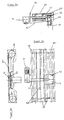
- FIGS. 2a and 2b A preferred embodiment of a turntable 12 is shown in FIGS. 2a and 2b, which are discussed together below.
- Fig. 2a shows a section through the turntable according to Fig. 2b along the section line A-A.
- the turntable 12 has a rubber layer 36 vulcanized onto a base part 34.
- the rubber layer preferably has a Shore hardness of about 85.
- the base part 34 of the turntable 12 only with a profile that is capable of transmitting a corresponding angular momentum to a transport good 24. It is only necessary that the surface or the friction surface 38 of the turntable 12 has a high coefficient of friction. This is preferably greater than approximately 0.2, but is at least 0.1.
- the numerical values given can be both the static friction number and the sliding friction number or an interpolation between them, depending on the alignment speed that is used.
- the surface or friction surface 38 of the turntable 12 has a curvature.
- a bevel 40 is provided, which can additionally facilitate the accumulation of the transport goods 24 to be aligned.
- the recesses 42, 44 are used to mount the turntable on an axis of rotation via which the turntable 12 is connected to a drive.
- the holes 46 are intended as bushings for fasteners and can be either smooth or threaded.
- the recesses 48 are filled with the rubber material during vulcanization. Instead of the rubber material of the vulcanized layer 36, a layer of one or more vulcanized elastomers and / or one or more plastics can also be provided.
- FIG. 2b The positions shown in FIG. 2b result from the description of FIG. 2a.
- FIGS. 3a and 3b A further embodiment of the device according to the invention can be seen from FIGS. 3a and 3b.
- a turntable 12 is shown, which has a mushroom shape.
- the two-way arrow 43 indicates that the turntable 12 can be lowered and raised.
- the vertical sectional view also shows a transport roller 46 which is driven at a different speed than the peripheral speed of the turntable 12.
- the top view according to FIG. 3b also reveals the turntable 12 according to FIG. 3a.
- Baffles 26 are arranged so that the supply of goods to be rotated or aligned is supported.
- the baffles 26 are adjustable so that they can be adapted to the supply of transport goods of different dimensions.
- the transport rollers 46 run over almost the entire width of the horizontal conveyor. In the area of the turntable 12, the rollers 46 are shortened according to the diameter of the turntable 1. It goes without saying that the rollers 46 are essentially driven transport rollers.
- a video camera arranged approximately shortly in front of the turntable 12, which is equipped, for example, with a light-sensitive semiconductor array, can signal the orientation of the transport goods in question .
- the corresponding signals can be passed on to a control device, which then causes the turntable 12 to either be raised into the working position via the transport plane of the transport rollers 46 or to be lowered below this into the rest position.
- the turntable 12 is inclined.
- the turntable 12 is inclined upward toward the center of the conveyor 20.
- the inclination of the turntable 12 should be adjustable.
- the entire turntable construction can in turn be moved in height, which is to be represented by the vertical two-way arrow 43.
- 4a is in its active position, in which it protrudes a little from the conveying plane. In order to bring it into an inactive position so that goods can easily pass through, it can either be moved downwards along arrow 43 or, if space permits, can be tilted accordingly.
- the continuously variable electric motor 41 which is arranged on the axis 44 of the turntable 12, provides the necessary rotational speed of the turntable 12.
- the device shown in FIGS. 4a, 4b and 4c has hinge straps 20 as horizontal conveying means.
- the hinge band 20 ' which also extends in the area of the turntable 12, is passed beneath it in the area of the turntable 12. The deflection takes place via additional deflection rollers 52.
- the guidance of the hinge band 20 ' can be seen in particular from FIG. 4b.
- the hinge band 20 ' like the hinge band 20, is guided endlessly by the deflection or drive rollers 50.
- the hinge band 20 ' is passed under the turntable 12 in the area thereof.
- FIGS. 4a and 4b shows the embodiment according to FIGS. 4a and 4b again in a top view. Attention should be drawn to the deflection rollers 52 which are intended to guide the hinge strap 20 'in the region of the turntable 12 and the hinge strap 20' under the turntable 12.
- the railings or baffles 26, which are intended to support the feeding of the goods to be aligned and the further conveying of the aligned goods 24, can be adjusted by means of adjusting devices 15 which are supported on the frame 14 of the hinged belt table.
- accumulation conveyor chains should be arranged on the hinge belts in order to take into account the special requirements of these goods to be transported 24.
- a coating of one or more vulcanized elastomers, as well as one or more plastics, can also be considered in the inclined embodiment for the rotary plate 12.
- a coupling device can be provided, e.g. a magnetic coupling, so that the turntable 12 has no aligning or rotating function even if it is not lowered below the conveying level of the flat top chains 20, 20 '.
- FIGS. 5a to 5c A further embodiment can be seen from FIGS. 5a to 5c, in which a turntable 12 whose angle of inclination is adjustable is provided.
- the turntable 12 is inclined downwards towards the center of the conveyor 20.
- This turntable 12 can also, as indicated by the two-way arrow 43 (FIG. 5a), Sink completely below the conveyor level of the flat top chain 20, 20 'or partially push it out.
- the angle of inclination of the turntable 12 can be adjusted via a mechanism 60. It is possible to vary the angle of inclination of the plate 12 by means of adjusting screws.
- the turntable 12 is in its active position, in which it exerts an angular momentum on transport goods 24 to be aligned, and partially under the hinged belt chains 20. Only the hinged belt chain 20 'is guided under the turntable 12 via deflection rollers 52 under it.
- the drive motor 41 for the turntable 12 is not arranged on the axis of the turntable 12 but laterally on the hinge band table 18. In this case, a chain or a belt 62 is required for the drive transmission.
- the turntable 12 (applies to all embodiments) can be shifted inwards normally to the conveying direction of the horizontal conveyor 18, 20 if the special size of a transport item 24 to be aligned should require this.
- both active and partially passive rollers, accumulation conveyor chains, hinge chains or slat conveyor chains can be used to achieve the horizontal conveyor.
- a combination of accumulation conveyor chains attached to hinged belt chains also comes for particularly bulky goods, e.g. Cardboard boxes or trays, in question.
- the active part of the turntable 12 projects into the path of the horizontal conveyor, while the inactive part protrudes beyond the edge of the horizontal conveyor and thereby takes up additional space.
- the turntable 12 does not protrude beyond the right edge of the horizontal conveyor, so that overall less space is required.
- the transport goods are accelerated by the turntable 12, so that a sequence of transport goods is pulled apart and thus transport goods can be aligned at relatively short distances from one another.
- a turntable ie a circular rotating surface
- rotating surfaces with a polygonal shape can also be used are used, in particular with a rectangular or square shape.
- this requires a synchronization or clocking with the incoming goods, which creates additional effort.
Landscapes
- Engineering & Computer Science (AREA)
- Mechanical Engineering (AREA)
- Attitude Control For Articles On Conveyors (AREA)
- Specific Conveyance Elements (AREA)
Applications Claiming Priority (2)
| Application Number | Priority Date | Filing Date | Title |
|---|---|---|---|
| DE4036627 | 1990-11-16 | ||
| DE19904036627 DE4036627C2 (de) | 1990-11-16 | 1990-11-16 | Vorrichtung zum Drehen von Transportgütern |
Publications (1)
| Publication Number | Publication Date |
|---|---|
| EP0486043A1 true EP0486043A1 (fr) | 1992-05-20 |
Family
ID=6418428
Family Applications (1)
| Application Number | Title | Priority Date | Filing Date |
|---|---|---|---|
| EP91119513A Withdrawn EP0486043A1 (fr) | 1990-11-16 | 1991-11-15 | Dispositif de rotation pour des objets transportés |
Country Status (2)
| Country | Link |
|---|---|
| EP (1) | EP0486043A1 (fr) |
| DE (1) | DE4036627C2 (fr) |
Cited By (13)
| Publication number | Priority date | Publication date | Assignee | Title |
|---|---|---|---|---|
| US5706929A (en) * | 1995-04-17 | 1998-01-13 | Alvey, Inc. | Conveyor with high speed case turner |
| EP1180484A3 (fr) * | 2000-08-16 | 2004-08-11 | Multi-Tech. Deurne B.V. | Station d'alignement fin et sa méthode d'opération |
| EP1224138A4 (fr) * | 1999-09-28 | 2007-03-07 | Esco Electronics Corp | Dispositif et procede de detection et de verification de courrier |
| US7402129B2 (en) | 2004-05-04 | 2008-07-22 | Heidelberger Druckmaschinen Ag | Folding-box gluing machine for producing folding boxes from blanks |
| WO2013079233A1 (fr) * | 2011-12-01 | 2013-06-06 | Dücker Fördertechnik GmbH | Procédé et dispositif permettant de faire pivoter une pile |
| EP3075686A1 (fr) * | 2015-04-02 | 2016-10-05 | Gebo Packaging Solutions France | Dispositif et méthode de rotation de produit |
| EP3444208A1 (fr) * | 2017-08-11 | 2019-02-20 | Intelligrated Headquarters LLC | Déchargeur de cartons robotique |
| EP3552994A1 (fr) * | 2018-04-13 | 2019-10-16 | Gebo Packaging Solutions Italy SRL | Dispositif d'orientation et procédé d'orientation d'un objet sur un convoyeur |
| US10807805B2 (en) | 2013-05-17 | 2020-10-20 | Intelligrated Headquarters, Llc | Robotic carton unloader |
| US10829319B2 (en) | 2013-05-17 | 2020-11-10 | Intelligrated Headquarters, Llc | Robotic carton unloader |
| US10906742B2 (en) | 2016-10-20 | 2021-02-02 | Intelligrated Headquarters, Llc | Carton unloader tool for jam recovery |
| CN115339859A (zh) * | 2022-08-12 | 2022-11-15 | 人本股份有限公司 | 用于汽车轮毂轴承法兰结构正位的装置 |
| WO2024109134A1 (fr) * | 2022-11-21 | 2024-05-30 | 中车长江铜陵车辆有限公司 | Dispositif de regroupement continu à l'extrémité arrière d'une ligne de transport |
Families Citing this family (3)
| Publication number | Priority date | Publication date | Assignee | Title |
|---|---|---|---|---|
| DE9318559U1 (de) * | 1993-12-06 | 1994-02-17 | Gebo Production, Reichstett | Transportgutdrehvorrichtung |
| DE29509067U1 (de) * | 1995-06-01 | 1996-07-18 | KRONES AG, 93073 Neutraubling | Prüfvorrichtung |
| DE102004052784A1 (de) * | 2004-10-30 | 2006-05-04 | Khs Maschinen- Und Anlagenbau Ag | Drehstation |
Citations (5)
| Publication number | Priority date | Publication date | Assignee | Title |
|---|---|---|---|---|
| DE1028032B (de) * | 1955-04-09 | 1958-04-10 | Hans Lingl | Vorrichtung zum Absetzen von Ziegelformlingen auf Traglatten |
| DE1283151B (de) * | 1967-01-14 | 1968-11-14 | Enzinger Union Werke Ag | Vorrichtung zum Drehen von rechteckigen Stueckguetern auf einer geraden Transportbahn |
| FR2226339A1 (fr) * | 1973-04-18 | 1974-11-15 | Gemmani Giuseppe | |
| US4669602A (en) * | 1981-07-30 | 1987-06-02 | Ouellette Machinery Systems, Inc. | Product turning device for conveyor |
| FR2637877A1 (fr) * | 1988-10-14 | 1990-04-20 | Cazas Ets | Convoyeur a rouleaux |
Family Cites Families (8)
| Publication number | Priority date | Publication date | Assignee | Title |
|---|---|---|---|---|
| DE1062163B (de) * | 1957-07-16 | 1959-07-23 | Fek Fuer Bau Keramik Und Hartz | Drehvorrichtung in einer geradlinig von der Strangpresse ueber den Abschneider weiterlaufenden zweiteiligen Foerderbahn |
| LU55858A1 (fr) * | 1968-04-09 | 1969-11-13 | ||
| DE2438181A1 (de) * | 1974-08-06 | 1976-02-19 | Roller Fa A | Umlenkvorrichtung |
| FI69814C (fi) * | 1981-03-24 | 1986-05-26 | Will E C H Gmbh & Co | Anordning foer aendring av transportriktningen hos enskilda foremaol |
| US4676361A (en) * | 1985-09-03 | 1987-06-30 | Heisler Raymond A | Troughing conveyors for carton or bag orienting and conveying |
| DE3614202A1 (de) * | 1986-04-26 | 1987-10-29 | Leifeld & Lemke Maschf | Vorrichtung zum ueberfuehren von produkten, insbesondere buecher, in eine gedrehte neue lage |
| JPH0790896B2 (ja) * | 1988-04-28 | 1995-10-04 | 住友金属鉱山株式会社 | 複合部品整列装置 |
| JPH06164620A (ja) * | 1992-11-20 | 1994-06-10 | Nec Corp | Atmシステムのセル流量測定回路 |
-
1990
- 1990-11-16 DE DE19904036627 patent/DE4036627C2/de not_active Expired - Fee Related
-
1991
- 1991-11-15 EP EP91119513A patent/EP0486043A1/fr not_active Withdrawn
Patent Citations (5)
| Publication number | Priority date | Publication date | Assignee | Title |
|---|---|---|---|---|
| DE1028032B (de) * | 1955-04-09 | 1958-04-10 | Hans Lingl | Vorrichtung zum Absetzen von Ziegelformlingen auf Traglatten |
| DE1283151B (de) * | 1967-01-14 | 1968-11-14 | Enzinger Union Werke Ag | Vorrichtung zum Drehen von rechteckigen Stueckguetern auf einer geraden Transportbahn |
| FR2226339A1 (fr) * | 1973-04-18 | 1974-11-15 | Gemmani Giuseppe | |
| US4669602A (en) * | 1981-07-30 | 1987-06-02 | Ouellette Machinery Systems, Inc. | Product turning device for conveyor |
| FR2637877A1 (fr) * | 1988-10-14 | 1990-04-20 | Cazas Ets | Convoyeur a rouleaux |
Cited By (19)
| Publication number | Priority date | Publication date | Assignee | Title |
|---|---|---|---|---|
| US5706929A (en) * | 1995-04-17 | 1998-01-13 | Alvey, Inc. | Conveyor with high speed case turner |
| EP1224138A4 (fr) * | 1999-09-28 | 2007-03-07 | Esco Electronics Corp | Dispositif et procede de detection et de verification de courrier |
| EP1180484A3 (fr) * | 2000-08-16 | 2004-08-11 | Multi-Tech. Deurne B.V. | Station d'alignement fin et sa méthode d'opération |
| US7402129B2 (en) | 2004-05-04 | 2008-07-22 | Heidelberger Druckmaschinen Ag | Folding-box gluing machine for producing folding boxes from blanks |
| WO2013079233A1 (fr) * | 2011-12-01 | 2013-06-06 | Dücker Fördertechnik GmbH | Procédé et dispositif permettant de faire pivoter une pile |
| US10829319B2 (en) | 2013-05-17 | 2020-11-10 | Intelligrated Headquarters, Llc | Robotic carton unloader |
| US10807805B2 (en) | 2013-05-17 | 2020-10-20 | Intelligrated Headquarters, Llc | Robotic carton unloader |
| EP3075686A1 (fr) * | 2015-04-02 | 2016-10-05 | Gebo Packaging Solutions France | Dispositif et méthode de rotation de produit |
| FR3034409A1 (fr) * | 2015-04-02 | 2016-10-07 | Gebo Packaging Solutions France | Dispositif et methode de rotation de produit |
| WO2016156753A1 (fr) * | 2015-04-02 | 2016-10-06 | Gebo Packaging Solutions France | Dispositif et methode de rotation de produit |
| US10906742B2 (en) | 2016-10-20 | 2021-02-02 | Intelligrated Headquarters, Llc | Carton unloader tool for jam recovery |
| EP3444208A1 (fr) * | 2017-08-11 | 2019-02-20 | Intelligrated Headquarters LLC | Déchargeur de cartons robotique |
| EP3552994A1 (fr) * | 2018-04-13 | 2019-10-16 | Gebo Packaging Solutions Italy SRL | Dispositif d'orientation et procédé d'orientation d'un objet sur un convoyeur |
| CN112105570A (zh) * | 2018-04-13 | 2020-12-18 | 西德尔线路和隧道解决方案公司 | 用于定向物体的定向装置与方法 |
| WO2019197205A1 (fr) * | 2018-04-13 | 2019-10-17 | Gebo Packaging Solutions Italy Srl | Dispositif d'orientation et procédé permettant l'orientation d'un objet |
| US11299354B2 (en) * | 2018-04-13 | 2022-04-12 | Sidel Spa | Orienting device and a method for orienting an object |
| CN112105570B (zh) * | 2018-04-13 | 2022-06-21 | 西德尔线路和隧道解决方案公司 | 用于定向物体的定向装置与方法 |
| CN115339859A (zh) * | 2022-08-12 | 2022-11-15 | 人本股份有限公司 | 用于汽车轮毂轴承法兰结构正位的装置 |
| WO2024109134A1 (fr) * | 2022-11-21 | 2024-05-30 | 中车长江铜陵车辆有限公司 | Dispositif de regroupement continu à l'extrémité arrière d'une ligne de transport |
Also Published As
| Publication number | Publication date |
|---|---|
| DE4036627A1 (de) | 1992-05-21 |
| DE4036627C2 (de) | 1994-05-26 |
Similar Documents
| Publication | Publication Date | Title |
|---|---|---|
| EP1498370B1 (fr) | Dispositif pour orienter des articles | |
| EP0616961B1 (fr) | Dispositif de séparation et d'alignement à haute vitesse d'articles | |
| EP0486043A1 (fr) | Dispositif de rotation pour des objets transportés | |
| EP3652096B1 (fr) | Dispositif de stockage et de convoyeur et procédé de fonctionnement du dispositif de stockage et de convoyeur | |
| EP3115322B1 (fr) | Procede et dispositif destines a la depalettisation de pneus | |
| EP1046599B1 (fr) | Dispositif pour transporter des articles plans | |
| CH671566A5 (fr) | ||
| EP1464595A2 (fr) | Système de transport de conteneurs, en particulier un tapis de transport de valises pour aéroport | |
| EP0581398B1 (fr) | Porte-charges et dispositif pour leur vidange | |
| CH711791A1 (de) | Fördersystem. | |
| DE2755147A1 (de) | Foerderanlage, insbesondere schleppkettenkreisfoerderer | |
| EP0727370B1 (fr) | Installation de transport | |
| EP3450355B1 (fr) | Installation de transport | |
| DE2211793B2 (de) | Vorrichtung zum bereitstellen von gefaessen | |
| DE102011108919B4 (de) | Mehrspurige Schalenverschließmaschine | |
| EP0582962A1 (fr) | Dispositif pour transférer des articles, notamment des paquets, d'un premier convoyeur à un second | |
| CH616386A5 (en) | Device for transferring units of product, continuously conveyed in on a conveyor belt, onto a support | |
| DE4114475A1 (de) | Vorrichtung zum einweisen von kontinuierlich zulaufenden stueckguetern | |
| EP2551221B1 (fr) | Dispositif de rotation d'objets plats | |
| DE102006024657A1 (de) | Vorrichtung und Verfahren zum Drehen von Transportgütern | |
| DE3826638C2 (fr) | ||
| EP3305691A1 (fr) | Système de transport doté d'un dispositif de guidage | |
| EP0588144A1 (fr) | Machine de tri pourvue de dispositifs de transport | |
| DE19546887A1 (de) | Förderbahn für Paletten | |
| EP3841040B1 (fr) | Bande de dépôt destinée à un dispositif de palettisation |
Legal Events
| Date | Code | Title | Description |
|---|---|---|---|
| PUAI | Public reference made under article 153(3) epc to a published international application that has entered the european phase |
Free format text: ORIGINAL CODE: 0009012 |
|
| AK | Designated contracting states |
Kind code of ref document: A1 Designated state(s): AT BE CH DE DK ES FR GB GR IT LI LU NL |
|
| 17P | Request for examination filed |
Effective date: 19920629 |
|
| 17Q | First examination report despatched |
Effective date: 19930112 |
|
| STAA | Information on the status of an ep patent application or granted ep patent |
Free format text: STATUS: THE APPLICATION HAS BEEN WITHDRAWN |
|
| 18W | Application withdrawn |
Withdrawal date: 19931112 |