EP2551221B1 - Dispositif de rotation d'objets plats - Google Patents
Dispositif de rotation d'objets plats Download PDFInfo
- Publication number
- EP2551221B1 EP2551221B1 EP12177488.9A EP12177488A EP2551221B1 EP 2551221 B1 EP2551221 B1 EP 2551221B1 EP 12177488 A EP12177488 A EP 12177488A EP 2551221 B1 EP2551221 B1 EP 2551221B1
- Authority
- EP
- European Patent Office
- Prior art keywords
- objects
- pin
- rotation
- conveyor system
- holding
- Prior art date
- Legal status (The legal status is an assumption and is not a legal conclusion. Google has not performed a legal analysis and makes no representation as to the accuracy of the status listed.)
- Not-in-force
Links
- 230000033001 locomotion Effects 0.000 claims description 18
- 230000000694 effects Effects 0.000 claims description 11
- 239000013013 elastic material Substances 0.000 claims description 3
- 238000013016 damping Methods 0.000 claims 1
- 238000011144 upstream manufacturing Methods 0.000 claims 1
- 239000000463 material Substances 0.000 description 6
- 230000001133 acceleration Effects 0.000 description 3
- 230000000977 initiatory effect Effects 0.000 description 3
- 238000004519 manufacturing process Methods 0.000 description 3
- 239000004033 plastic Substances 0.000 description 2
- 229920003023 plastic Polymers 0.000 description 2
- 230000006978 adaptation Effects 0.000 description 1
- 230000005540 biological transmission Effects 0.000 description 1
- 238000006243 chemical reaction Methods 0.000 description 1
- 239000011248 coating agent Substances 0.000 description 1
- 238000000576 coating method Methods 0.000 description 1
- 230000001419 dependent effect Effects 0.000 description 1
- 230000000994 depressogenic effect Effects 0.000 description 1
- 238000000034 method Methods 0.000 description 1
- 238000012986 modification Methods 0.000 description 1
- 230000004048 modification Effects 0.000 description 1
- 230000002093 peripheral effect Effects 0.000 description 1
- 239000006223 plastic coating Substances 0.000 description 1
- 230000000284 resting effect Effects 0.000 description 1
- 239000013589 supplement Substances 0.000 description 1
Images

Classifications
-
- B—PERFORMING OPERATIONS; TRANSPORTING
- B65—CONVEYING; PACKING; STORING; HANDLING THIN OR FILAMENTARY MATERIAL
- B65G—TRANSPORT OR STORAGE DEVICES, e.g. CONVEYORS FOR LOADING OR TIPPING, SHOP CONVEYOR SYSTEMS OR PNEUMATIC TUBE CONVEYORS
- B65G47/00—Article or material-handling devices associated with conveyors; Methods employing such devices
- B65G47/22—Devices influencing the relative position or the attitude of articles during transit by conveyors
- B65G47/24—Devices influencing the relative position or the attitude of articles during transit by conveyors orientating the articles
- B65G47/244—Devices influencing the relative position or the attitude of articles during transit by conveyors orientating the articles by turning them about an axis substantially perpendicular to the conveying plane
Definitions
- the present invention relates to a device for turning flat objects, in particular carton blanks, with a transport path, over which or along which the objects are transported flat in a transport direction T by means of rollers and / or belts, with a rotating device which is adapted to rotate the articles during the continuous transport, the rotating device having a mechanical pin which is movable in a transverse direction in relation to the transport direction from the inside to the outside of the transport path such that the object is rotated braked.
- the device for rotating according to the invention as defined in claim 1 comprises a transport path over which the objects are transported flat in a transporting direction T by means of rollers and / or belts, and a rotating device which is adapted is to rotate the articles during the continuous transport, wherein the rotating device has a mechanical pin, which in a transverse direction Q relative to the transport direction T from an inside to outside of the transport path is movable such that the object is rotated braked. Therefore, the flat objects no longer abruptly abut on a fixed element of the rotating means, but the mechanical pin of the rotating device according to the invention is laterally moved during the transport of the flat objects, that a braked rotation of the flat objects is achieved.
- the lateral movement of the mechanical pin of the rotator is such that an abrupt abutment of a corner of the carton blanks or the like is avoided and that at the same time the angular momentum is transmitted to the flat objects, which then ultimately to a 90 ° rotation about a vertical Axis without damaging the corners or edges leads.
- the rotating device and the transversely movable mechanical pin are according to the invention designed such that the lateral movement of an inner side, ie, a central region of the transport path, outwardly controllable, so that the braked rotation of the objects is effected.
- the pin of the rotary device in cross section has a substantially round shape with a segment-shaped straight cutout on one side and is provided with a suction device for holding the objects on the pin during the braked rotation.
- the carton blanks or flat objects are held during the rotation, as it were, by the suction device on the straight cutout of the pin, so that unintentional slippage or misalignment is reliably avoided.
- the pin can be so actively involved in the application of the angular momentum, which improves the control of the rotation.
- the adjusting movement of the mechanical pin of the rotary device is controllable such that a center of the article after the rotation remains approximately in a central axis M of the transport path. This avoids having to reorient the flat objects after rotation.
- the turned carton blanks are located directly in the middle of the transport route and can easily be further processed and handled in the following stations.
- a control of the adjustment movement in the transverse direction of the mechanical pins of the rotating device according to the invention can be done for example by the speed, the initial and final position of the pin, a targeted slowing down of the adjustment or the like.
- the pin of the rotary device engages seen on a front side of the flat object in the transport direction.
- the angular momentum is thus applied from the front of the article.
- the mechanical pin of the rotary device does not attack on the front side, but in a front region on a side edge of the object.
- This alternative has the advantage that even with narrow carton blanks, which provide only a relatively narrow attack surface on the front, a reliable turning without damage is achieved.
- a braked rotation with the mechanical pin is deliberately caused, so that any damage to the edges on the side region are prevented, as well as in the alternative embodiment, in which the rotation is initiated at the front.
- the mechanical pin of the rotary device with a dampened elastic material or it is made of such an impact absorbing elastic material. This further reduces the risk of damage, since the carton blanks striking the turning device do not strike a hard element but an element with a shock-absorbing surface.
- Suitable materials for this purpose for example, elastic plastics or rubber materials in question.
- the mechanical and transversely movable pin of the rotary device is rotatably mounted about a vertical axis X. This allows the pin to roll along, as it were, the side edge of the carton blanks, and no friction or pressure is applied to the side edge by the movement of the pin. This further reduces the risk of damage.
- the pin is non-rotatably mounted, i. it is fixedly attached to the rotating device. In this case, the angular momentum is also applied to the flat objects and not just by the movement of the pin in the transverse direction.
- the pin is driven to support the braked rotation of the flat objects.
- the pin which in this variant is preferably round or at least elliptical in shape, is driven in rotation about a vertical axis of rotation by a suitable means, such as an electric motor, so that the initiation of the rotary movement can still be intensified and the control possibilities of the latter braked Rotation are even more versatile.
- the drive of the pin is preferably controlled such that the carton blanks passing by on the transport route are in their Rotational movement and not be reinforced against the rotation.
- the mechanical pin of the rotary device in cross-section on an elliptical shape.
- the elliptical shape of the mechanical pins causes already due to the shape of a different speed is applied to the objects in the course of the adjustment in the transverse direction.
- the elliptical shape acts as a kind of mechanical braking or accelerating means that decelerates or accelerates the rotation by itself.
- the mechanical pin may also have a circular shape in cross section.
- the pin of the rotary device has a receiving slot adapted to the thickness of the flat objects on its outer periphery.
- the arranged in the horizontal direction corresponding to the transport path circumferential receiving slot provides for the incoming flat objects a kind of additional support in which the side edge or the leading edge of the objects from three sides is virtually embraced.
- the handling of the carton blanks to effect the 90 ° rotation can be improved.
- the mechanical pin of the rotary device in longitudinal section on a downwardly tapered frustoconical shape.
- the objects are pressed down slightly as they hit the pin.
- the means of transport such as the belts or rollers.
- At least one vacuum device is provided below the transport path.
- the vacuum means or suction means may be used to assist the initiation of the rotary motion and to align the carton blanks carried over them.
- at least two parallel vacuum devices are provided next to each other below the transport path.
- alignment means for the alignment of the objects are provided after the rotation. If, after rotation, the objects are no longer in a straight or desired orientation along the conveyor line, they can be returned to the correct orientation.
- a means for aligning the objects after the rotation for example, parallel conveyor belts may be provided, which are independently controllable.
- alignment means in the form of a lifting plate may also be present.
- a lifting plate is a flat sheet-like element in the plane of the transport route and the side of the transport route. The flat objects conveyed above are raised slightly by the lifting plate in the event of misalignment, whereby a kind of further braking effect on the objects laterally is effected. This will bring the items back to their correct orientation and position.
- At least one conveyor belt is provided in the transport path, which is equipped with at least one vacuum device which can generate a suction effect on the objects to control the transport.
- the belts of the transport route are thus suitable not only to ensure safe transport, but also to influence the transported carton blanks in their position and their direction of movement by different braking or holding by the generated suction effect. Likewise, this can be specifically supported the rotation of the objects.
- the pin is driven counter to the direction of rotation of the objects to be rotated during the turning operation and is provided from above on the objects, biased hold-down at least in the area in front of the pin in the transport direction.
- the pin is actively driven to assist and initiate the turning operation of this embodiment.
- the sideways movement of the incoming carton blanks is thereby carried out faster and safer.
- the hold-down is installed with a defined bias.
- the hold-down can be biased for example with mechanical springs.
- the relative position between the objects to be rotated and the actively driven pin of the rotating device is thus securely determined.
- As hold-down according to the present Invention is preferably used such a hold-down, which opposes the rotational movement as little resistance as possible.
- a further advantageous related embodiment of the invention is provided as hold-down a number of freely rotatable balls in a ball cage.
- the balls are mounted over the transport path so that they exert a slight pressure from above, depending on the thickness of the objects.
- the hold-down is designed to be adjustable in its bias and / or its height. With different bias voltages can hold different strengths holding forces on the objects. A height adjustment is used to adapt to different thickness carton blanks or the like.
- at least two balls are provided as hold-down, which can rotate freely in a cage and which are independently adjustable in their bias. In this way, the foremost ball, which is reached by the carton blank first, can be set with a lower bias than the subsequent ball (s). This has the advantage that even pressure sensitive flat objects can be securely twisted without damage with the device according to the invention.
- At least one driven roller of the transport path in the region of the hold-down, i. preferably provided directly below the hold-down, at least one driven roller of the transport path, which at least partially has a friction-increasing surface.
- the driven roller with the surface increased in friction is operated at the same speed as the remaining elements of the transport path, and it supports the uniform movement of the carton blanks in spite of the action of the pin of the rotating device, which initiates and performs the turning operation.
- a friction-increasing surface of the roller can be realized, for example, in the form of a coating with a plastic or rubber material or with a glued or sprayed-on material layer on the outer diameter of the roller.
- the second hold-down behind the rotating device has the advantage that the carton blanks are selectively braked after the turning process. Due to the rotation by 90 °, the objects after rotation have an increased speed, especially on the outside, so that with the downstream holding-down device in the form of rotating balls, the carton blanks can be selectively braked at these areas.
- the pin of the rotary device on its peripheral surface brush-like bristles.
- the contact surface the pin which detects the incoming carton blanks is thus quasi padded, and damage to the edges of the objects to be twisted is prevented.
- the bristles allow a secure gripping and lateral movement in the direction of rotation, and the bristles can also engage in lateral openings of carton blanks and thus ensure the fast and safe twisting.
- the Fig. 1 and 2 show in perspective views a first embodiment of an inventive device 10 for rotating flat objects such as cardboard blanks 1.
- the carton blanks 1 are along a transport path 2 in the transport direction T, ie from right to left in the Fig. 1 transported by a plurality of transport means, such as belts 4 and rollers or rollers 3.
- the turning device 10 is configured as a component or as a module of a larger plant for the production of cardboard blanks.
- the carton blanks are stamped, folded, glued or otherwise processed in other stations of such a facility.
- the rotary device 10 according to the invention serves to rotate the conveyed on the transport path 2 Carton blanks 1 to about 90 °.
- a turning device 5 engaging from above is provided, by means of which the cardboard blanks 1, which are initially aligned in the longitudinal direction, can be turned in a transverse orientation (cf., carton blank 1 in front of the turning device 5 and carton blank 1 after the turning device 5 in FIG Fig. 1 ).
- the rotating device 5 is mounted in this embodiment on a kind of bridge or crossbeam over a trolley or the like above the transport path 2, so that the rotating device 5 together with the actual rotation serving pin 6 in the transverse direction Q in relation to the transport direction T are selectively controlled controlled can.
- the incoming carton blanks 1 are usually conveyed along a center axis M of the transport path 2, and the pin 6 of the rotator 5 is moved to such a position that it engages in this embodiment at the front edge of the carton blank 1 and generates an angular momentum, as it the situation of Fig. 1 clarified.
- the rotating device 5 is specifically controlled with the pin 6:
- the rotating device 5 is during the impingement of the carton blank 1 to be rotated from an inside to the outside of the transport path 2, ie in the transverse direction Q, moved.
- a kind of decelerated angular momentum is transmitted to the carton blank 1 to be turned.
- the rotation is supported by 90 °, so that the carton blank in the transport direction T after the rotator 5 undamaged and safely in the desired twisted position (transverse orientation) comes to rest on the transport path 2 and in this situation can be further transported to the subsequent stations of processing or a stacking device, etc.
- the mechanical pin 6 is formed from an upwardly projecting axis for mounting and with an elliptical in cross-section pin 6.
- the pin 6 is additionally driven in this embodiment about a vertical axis X over that in the Fig. 2 indicated gear of two gears and an electric motor or the like.
- By the elliptical shape of the pin 6 and by driving the pin 6 via a targeted control accelerations and decelerations can be effected in the application of the angular momentum.
- the rotation of the pin 6 about the axis X for example, be driven so that a gentle deceleration is achieved when hitting the carton blank 1 and then an accelerated rotation of the carton blank 1 on the transport path 2 is caused.
- a plurality of rollers 3 is provided in this embodiment, then there is the transport path 2 of parallel belts 4 (see also Fig. 1 ), each provided with vacuum means at the bottom of the transport path 2, which will be described in detail below.
- the pin 6 of the rotating device 5 can be realized both as a driven pin and as a fixed, ie not rotatable about the vertical axis X pin.
- the adjustment of the rotary device 5 in the transverse direction Q is specifically controllable according to the invention, both in terms of speed and the starting position and end position and as regards acceleration or deceleration so that a deliberately braked rotation of the carton blanks 1 can be carried out according to the invention.
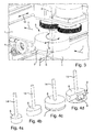
- a circular pin 6 is shown as a means for initiating the rotation, which can also be driven in rotation about a vertical drive axis X along.
- the pin 6 is further provided with a circumferential receiving slot 7, which is adapted in width to a thickness of the carton blanks 1 to be rotated.
- the one from the right side in the Fig. 3 incoming carton blanks 1 are thus in some way encompassed on three sides by the receiving slot 7 of the pin 6 and, as in the previous embodiment, rotated in a braked manner.
- the rotary device 5 in the transverse direction Q is specifically adjustable from the inside to the outside of the transport path 2, so that a braked rotation is effected for that reason alone.
- this effect can be further increased by driving the pin 6 in rotation about the vertical axis X.
- this is not absolutely necessary, and it may also be a fixed, ie not rotatable about the axis X driven pin 6 may be provided without departing from the scope of the invention.
- the Fig. 4a to 4d show in perspective views various alternative forms of a pin 6, which can be used in a rotating device 10 according to the present invention:
- the pin 6 after Fig. 4a is of a circular shape and has for mounting on the rotator 5 a vertically upward projecting mounting stem 14 or axis.
- the pin 6 may be driven in a rotator 5 or mounted as a fixed pin 6.
- the Fig. 4b shows an alternative form of a cross-sectionally approximately ellipsoidal pin 6, as he above in connection with the Fig. 2 has been described. Due to the elliptical shape accelerations and decelerations can be achieved in the application of the angular momentum on the carton blanks 1 targeted.
- the larger radius of the sections of the ellipse shape generate a lower speed than the smaller in radius areas of the elliptical pin 6.
- the rotational speed can be specifically braked and accelerated so that the carton blanks 1 safely and without Damage can be rotated, for example, a longitudinal alignment in a transverse orientation.
- Fig. 4c is another alternative of a pin 6 corresponding to that of the Fig. 3 shown.
- the pin 6 is also circular and has a receiving slot 7 on its outer periphery. Through the receiving slot 7, a front edge or side edge of the carton blank 1 is quasi encompassed from three sides, so that the power transmission is improved and a better holding effect is achieved. Also this pin 6 after the Fig.
- FIG. 4c can be both stationary and driven in rotation in the rotating device 5 mounted.
- FIG. 4d shown alternative of a possible embodiment of the pin 6 of the rotator 5 is a substantially circular pin formed on one side with a straight segmental cutout.
- a suction device 9 is mounted, by means of which a negative pressure or a vacuum can be generated, which serves to hold the flat objects 1 during the effect of the rotation.
- the carton blanks 1 are held virtually on the segment-shaped straight cutout of the pin 6 by the suction effect of the suction device 9, so that an active support of the rotation of the carton blanks 1 can be achieved by driving the pin 6. The rotation is thus even safer than in the case where the pin only passively causes the rotation.
- the pin 6 is selectively adjusted from a position from the inside to the outside of the transport path in a transverse direction in relation to the transport direction T during the rotation, so that the carton blanks after turning again in a substantially central orientation, ie centered on the central axis M of the transport line 2, come to rest.
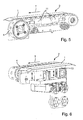
- FIG. 5 shows a band 4 with holes, which forms part of the transport path 2 of the rotating device 10.
- the band 4 is over in the Fig. 5 not shown motor means driven.
- At the bottom of the transport path 2 top of the band 4 in the Fig. 5 ) are each mounted two vacuum devices 11 for generating a suction effect.
- the conveyed on the transport path 2 flat object 1 can be selectively influenced, in particular for alignment after rotation, if the carton blank 1 is no longer positioned in the correct orientation.
- the transport path 2 consist of a plurality of parallel arranged such bands 4, which can be controlled separately according to the invention. By a different driving the speeds of the conveyor belts 4 can also be an orientation of the turned cardboard blanks 1 done.
- the bands 4 of the transport path 2 can also be used to support the rotation of the carton blanks 1, by being operated at different speeds or by one of two parallel juxtaposed tapes 4 is briefly stopped.
- FIG. 6 Another alternative of an alignment means according to the rotary device 10 of the present invention is shown in a detail view.
- a lifting plate 13 is present in addition to the conveyor belt 4, a lifting plate 13 is present.
- the lifting plate 13 is mounted on the underside of the transport path 2 and laterally thereof.
- the lifting plate 13 is provided with means for vertical adjustment of the lifting plate 13, as it is with the arrows in the Fig. 6 is indicated.
- the lifting plate 13 is raised, the carton blank conveyed on the conveying path 2 is also raised and thereby decelerated, so that an alignment in an exact position is possible.
- the two alignment means according to Fig. 5 and Fig. 6 may of course also be incorporated in combination in a rotating device 10 according to the present invention. They can also be used with the above-described variants of pins 6 alone or together in each case in a rotating device 10 according to the invention.
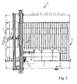
- a second embodiment of a rotary device 10 according to the invention is in the Fig. 7 and 8th and is explained below.
- the rotating device 10 is also provided in this second embodiment with a rotating device 5, which is provided on a kind bridge with trolley above a transport path 2 such that a provided on the rotating device 5 pin in the transverse direction Q, ie perpendicular to the transport direction T, specifically can be moved via a controller to perform the turning operation.
- the carton blanks 1 also come here aligned in the longitudinal direction of the rotating device and are detected by the rotator 5 via the pin 6 at the front edge and moved laterally.
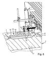
- the pin 6 is driven counter to the direction of rotation of the carton blanks in this embodiment, as shown in the Fig. 8 is illustrated with the arrow.
- a hold-down 15 is provided in the region of the rotating device 5, which acts from above on the objects to be rotated 1 to depressed them on the rollers 17 and other transport elements of the transport path 2.
- the hold-down 15 consists of a series of freely rotatable balls 16, which are held together in a kind of ball cage.
- the five balls 16 are freely rotatable in the ball cage, so that they do not oppose a rotation of the carton blanks 1 or provide the lowest possible resistance.
- the two foremost balls 16 of the blank holder 15 are biased with respective coil springs 18.
- the bias of Spiral springs 18 of the two front balls 16 is preferably independently adjustable, so that in pressure-sensitive objects 1, the bias can be adjusted progressively increasingly in the direction of transport direction T, for example, which avoids damage of particularly sensitive carton blanks, for example.
- the hold-down 15 in the form of a series of freely rotatable balls 16 is mounted in this embodiment in the longitudinal direction of the transport direction T.
- the row of balls of the blank holder 15 may also be slightly obliquely mounted in relation to the transport direction T, whereby the respective movement during rotation of the carton blanks 1 can be specifically taken into account.
- the Fig. 7 and 8th There are two driven rollers 17, which are each provided with a surface which increases a friction factor compared to the other rollers of the transport path 2.
- the driven rollers 17 thereby ensure a continuous and running at the same speed further transport along the transport path 2 in the region of the rotating means 5, which facilitates the control and execution of the turning operation with the driven pin 6.
- adhered material layers such as a rubber or plastic coating may be provided.
- the friction-increasing surfaces on the outer circumference of the rollers 17 can also be realized only partially in certain sections on the rollers 17.
- the hold-down 15 is arranged in the form of the five in series, freely rotatable balls 16 also adjustable in height. With this measure, the rotating device 5 can be adjusted specifically to different thicknesses of objects 1.
- the hold-down 5 can also be mounted in a slight slope in the longitudinal direction, so that narrow the distances from the balls 16 to the surface of the transport path 2, whereby a kind of wedging action and improved hold down also slightly upwardly projecting objects 1 is ensured. Since the balls 16 are freely rotatable within their cage of the blank holder 15, they allow a slight rotation of the carton blanks 1 and still ensure a secure resting on the transport path 2 for the turning operation. In the in the Fig.
- the carton blanks 1 With the hold-down 15 after the rotator 5, the carton blanks 1 are selectively braked. Since the outer area of the carton blanks 1 has a greatly increased speed during rotation, the position in the transverse direction Q of the carton blank 1 can thus be ensured by targeted braking.
- the shape and position of the downholders 15 can be varied in various ways. Only one hold-down device 15 can be provided, and the hold-down device can also have a different shape than the shape shown with five rotatable balls 16 connected in series.
Landscapes
- Engineering & Computer Science (AREA)
- Mechanical Engineering (AREA)
- Making Paper Articles (AREA)
Claims (14)
- Dispositif (10) pour la rotation d'objets plats (1), plus particulièrement de découpes de carton, avec un trajet de transport (2), sur lequel les objets (1) sont transportés dans la direction de transport (T) à plat à l'aide de rouleaux (3) et/ou de bandes (4), avec un dispositif de rotation (5) conçu pour tourner les objets (1) pendant le transport sur le trajet de transport (2), le dispositif de rotation (5) comprenant une broche mécanique (6) qui est mobile dans une direction transversale (Q) par rapport à la direction de transport (T) de l'intérieur vers l'extérieur du trajet de transport (2), de façon à ce que l'objet (1) soit tourné avec freinage, caractérisé en ce que la section transversale de la broche (6) présente globalement une forme ronde avec une section droite (8) en forme de segment et en ce que la broche (6) comprend un dispositif d'aspiration (9) pour maintenir les objets (1) pendant la rotation avec freinage.
- Dispositif selon la revendication 1, caractérisé en ce qu'un mouvement de réglage de la broche (6) du dispositif de rotation (5) est contrôlable dans la direction transversale (Q) de façon à ce qu'un centre de l'objet (1) reste, après la rotation, sur un axe central (M) du trajet de transport (2).
- Dispositif selon la revendication 1 ou 2, caractérisé en ce que la broche (6)- est en contact avec l'avant de l'objet (1), vu dans la direction de transport (T); et/ou- est en contact, dans la zone frontale, avec un bord latéral de l'objet (1), vu dans la direction de transport (T); et/ou- du dispositif de rotation (5) est entourée d'un matériau élastique amortisseur ou en est constituée; et/ou- est logée de manière rotative autour d'un axe vertical (X) ou montée de manière non rotative; et/ou- est entraînée pour assister la rotation freinée des objets (1); et/ou- présente une section transversale de forme elliptique; et/ou- comprend une fente de logement (7) adaptée à l'épaisseur des objets plats (1) sur sa périphérie extérieure; et/ou- présente, en coupe longitudinale, une forme se rétrécissant vers le bas ou de cône tronqué; et/ou- comprend, sur sa surface périphérique, des soies en forme de balais, plus particulièrement dépassant radialement.
- Dispositif selon l'une des revendications précédentes, caractérisé en ce que, sous le trajet de transport (2), au moins un dispositif à vide (11) conçu pour la production d'un effet d'aspiration sur les objets (1).
- Dispositif selon l'une des revendications précédentes, caractérisé en ce qu'un moyen d'alignement (12) est prévu pour l'alignement des objets (1) après la rotation.
- Dispositif selon la revendication 5, caractérisé en ce que le moyen d'alignement (12) est constitué de bandes (4) parallèles et contrôlables individuellement du trajet de transport (2).
- Dispositif selon la revendication 5 ou 6, caractérisé en ce que le moyen d'alignement (12) comprend une plaque de levage (13) disposée latéralement par rapport au trajet de transport (2).
- Dispositif selon l'une des revendications précédentes, caractérisé en ce que le trajet de transport (2) comprend au moins une bande de transport (4) qui est équipée d'au moins un dispositif à vide (11) à l'aide duquel, pour le contrôle du transport, un effet d'aspiration peut être produit sur les objets (1).
- Dispositif selon l'une des revendications 1 à 6 et 8, caractérisé en ce que la broche (6) est entraînée contre la direction de rotation des objets (1) pendant le processus de rotation et en ce qu'un serre-flan (15) précontraint agissant par en haut sur les objets (1) est prévu au moins dans la zone devant la broche (6) dans la direction de transport (T).
- Dispositif selon la revendication 9, caractérisé en ce que le serre-flan (15) comprend une série de billes (16) tournant librement dans une cage à billes.
- Dispositif selon la revendication 9 ou 10, caractérisé en ce que la précontrainte et/ou la hauteur du serre-flan (15) sont réglables.
- Dispositif selon l'une des revendications 9 à 11, caractérisé en ce qu'au moins deux billes (16) sont prévues en tant que serre-flans (15), dont les précontraintes sont réglables indépendamment les unes des autres.
- Dispositif selon l'une des revendications 9 à 12, caractérisé en ce que, au niveau du serre-flan, se trouve au moins un rouleau (17) entraîné du trajet de transport (2), qui présente au moins à certains endroits une surface augmentant la friction.
- Dispositif selon l'une des revendications précédentes, caractérisé en ce que dans la zone après le dispositif de rotation (5) se trouve un serre-flan (15) précontraint agissant par en haut sur les objets (1) sous la forme d'une série de billes (16) tournant librement.
Applications Claiming Priority (1)
| Application Number | Priority Date | Filing Date | Title |
|---|---|---|---|
| DE102011080102A DE102011080102A1 (de) | 2011-07-29 | 2011-07-29 | Vorrichtung zum Drehen flacher Gegenstände |
Publications (2)
| Publication Number | Publication Date |
|---|---|
| EP2551221A1 EP2551221A1 (fr) | 2013-01-30 |
| EP2551221B1 true EP2551221B1 (fr) | 2013-11-20 |
Family
ID=46603592
Family Applications (1)
| Application Number | Title | Priority Date | Filing Date |
|---|---|---|---|
| EP12177488.9A Not-in-force EP2551221B1 (fr) | 2011-07-29 | 2012-07-23 | Dispositif de rotation d'objets plats |
Country Status (2)
| Country | Link |
|---|---|
| EP (1) | EP2551221B1 (fr) |
| DE (1) | DE102011080102A1 (fr) |
Families Citing this family (4)
| Publication number | Priority date | Publication date | Assignee | Title |
|---|---|---|---|---|
| DE102013013809B4 (de) * | 2013-08-22 | 2020-12-10 | Maschinenbau U. Konstruktion Gmbh Elmshorn | Vorrichtung und Verfahren zur Veränderung der Ausrichtung von Gegenständen auf einem Förderer |
| WO2015192863A1 (fr) | 2014-06-16 | 2015-12-23 | Bobst Mex Sa | Procede, dispositif de rotation d'objets plans, module et machine de traitement ainsi equipee |
| CN110143012B (zh) * | 2019-05-23 | 2024-02-23 | 中科天工(广东)智能技术有限公司 | 纸张换向设备 |
| DE102023205343A1 (de) | 2023-06-07 | 2024-12-12 | Tripleye Gmbh | Vorrichtung zur räumlichen Bilderfassung einer relativ zur Vorrichtung bewegten Umgebung sowie Betriebsverfahren hierfür |
Family Cites Families (9)
| Publication number | Priority date | Publication date | Assignee | Title |
|---|---|---|---|---|
| US4312266A (en) * | 1980-05-30 | 1982-01-26 | Ovalstrapping, Inc. | Object-turning apparatus for a high-speed strapping machine |
| GB8806213D0 (en) * | 1988-03-16 | 1988-04-13 | Pakseal Ind Ltd | Improvements in bundle turning units for use with conveyors |
| FR2664577A1 (fr) * | 1990-07-11 | 1992-01-17 | Lys Ondulys Cartonneries | Dispositif a orienter des charges sur convoyeur lineaire et palettiseur presentant un tel convoyeur. |
| US5568920A (en) * | 1996-01-18 | 1996-10-29 | Moll; Richard J. | Turning device for transport apparatus |
| DE29613864U1 (de) * | 1996-08-10 | 1996-10-10 | Geyssel, Jürgen W., 50829 Köln | Vorrichtung zum Umsetzen von mit einem Transportmittel transportierten, etwa quaderförmigen Gegenständen |
| DE10043991A1 (de) | 2000-09-05 | 2002-04-04 | Jagenberg Diana Gmbh | Vorrichtung zum Drehen flacher Gegenstände, insbesondere von Faltschachtelzuschnitten |
| US6935484B2 (en) * | 2003-06-25 | 2005-08-30 | Production Automation Inc. | Case turning apparatus and method for a palletizer |
| JP2005126211A (ja) * | 2003-10-24 | 2005-05-19 | Kubota Matsushitadenko Exterior Works Ltd | 板材搬送装置 |
| DE202007010767U1 (de) * | 2007-07-31 | 2007-10-11 | Kock, Kay-Olaf | Vorrichtung zum Drehen einer Teilmenge von Produkten |
-
2011
- 2011-07-29 DE DE102011080102A patent/DE102011080102A1/de not_active Withdrawn
-
2012
- 2012-07-23 EP EP12177488.9A patent/EP2551221B1/fr not_active Not-in-force
Also Published As
| Publication number | Publication date |
|---|---|
| DE102011080102A1 (de) | 2013-01-31 |
| EP2551221A1 (fr) | 2013-01-30 |
Similar Documents
| Publication | Publication Date | Title |
|---|---|---|
| EP3115322B1 (fr) | Procede et dispositif destines a la depalettisation de pneus | |
| EP2407388B1 (fr) | Système de prise pour une machine de fermeture de coques | |
| EP0795503A2 (fr) | Procédé et dispositif pour aligner des objets plats | |
| DE2643709A1 (de) | Sortiervorrichtung fuer ungeordnet verteiltes stueckgut | |
| EP3102513B1 (fr) | Dispositif d'acheminement pour acheminer des pièces de bois coupées | |
| EP2551221B1 (fr) | Dispositif de rotation d'objets plats | |
| EP0608861A2 (fr) | Procédé et dispositif pour alimenter des objets sensibles dans une machine de traitement | |
| DE102009004967A1 (de) | Verfahren und Vorrichtung zur Ausrichtung von erwärmten Werkstücken | |
| EP2903919A1 (fr) | Dispositif de transport pour marchandises et procédé permettant de faire fonctionner un dispositif de transport | |
| EP0486043A1 (fr) | Dispositif de rotation pour des objets transportés | |
| DE102013100232A1 (de) | Verfahren und Vorrichtung zur Herstellung variabler Lücken zwischen Artikeln oder Artikelgruppen eines Artikelstroms | |
| DE102017210160B4 (de) | Transporteinrichtung, Transportsystem und Verfahren zum Transport von Gegenständen | |
| WO2017148713A1 (fr) | Dispositif et procédé pour le transport stable de contenants | |
| EP2055660B1 (fr) | Dispositif de retournement cadencé d'objets plats | |
| EP2100839B1 (fr) | Dispositif de transport pour le prèlévement et la transmission de produits imprimés | |
| EP2281765A2 (fr) | Dispositif et procédé correspondant pour déposer des produits | |
| EP3600709B1 (fr) | Procédé de cintrage de découpes de tôle pour des unités d'emballage et machine à souder à cordon longitudinal pour la fabrication de corps de boîtes comprenant un poste de cintrage | |
| EP2733091B1 (fr) | Dispositif d'acheminement d'au moins une pièce moulée dans une installation de remplissage de boissons | |
| DE60318739T2 (de) | Verfahren und vorrichtung zur handhabung von walzen | |
| EP3150344A1 (fr) | Ausrichtvorrichtung zum ausrichten von werkstücken sowie bearbeitungsmaschine | |
| WO2006122677A2 (fr) | Procede d'individualisation d'elements empiles en forme de disque et dispositif d'individualisation | |
| DE102018133455B4 (de) | Transportverfahren und Halte- und Fördervorrichtung | |
| DE102012207320B4 (de) | Saugtransportvorrichtung und Verfahren zur Abnahme eines Bogens von einem Bogenstapel | |
| DE19749498C2 (de) | Verfahren und Vorrichtung zum Vereinzeln flexibler flächiger Gegenstände | |
| EP3740445A1 (fr) | Transfert de marchandises de détail |
Legal Events
| Date | Code | Title | Description |
|---|---|---|---|
| PUAI | Public reference made under article 153(3) epc to a published international application that has entered the european phase |
Free format text: ORIGINAL CODE: 0009012 |
|
| 17P | Request for examination filed |
Effective date: 20121203 |
|
| AK | Designated contracting states |
Kind code of ref document: A1 Designated state(s): AL AT BE BG CH CY CZ DE DK EE ES FI FR GB GR HR HU IE IS IT LI LT LU LV MC MK MT NL NO PL PT RO RS SE SI SK SM TR |
|
| AX | Request for extension of the european patent |
Extension state: BA ME |
|
| GRAP | Despatch of communication of intention to grant a patent |
Free format text: ORIGINAL CODE: EPIDOSNIGR1 |
|
| RIC1 | Information provided on ipc code assigned before grant |
Ipc: B65G 47/244 20060101AFI20130618BHEP |
|
| INTG | Intention to grant announced |
Effective date: 20130705 |
|
| GRAS | Grant fee paid |
Free format text: ORIGINAL CODE: EPIDOSNIGR3 |
|
| GRAA | (expected) grant |
Free format text: ORIGINAL CODE: 0009210 |
|
| AK | Designated contracting states |
Kind code of ref document: B1 Designated state(s): AL AT BE BG CH CY CZ DE DK EE ES FI FR GB GR HR HU IE IS IT LI LT LU LV MC MK MT NL NO PL PT RO RS SE SI SK SM TR |
|
| REG | Reference to a national code |
Ref country code: GB Ref legal event code: FG4D Free format text: NOT ENGLISH |
|
| REG | Reference to a national code |
Ref country code: CH Ref legal event code: NV Representative=s name: DREISS PATENTANWAELTE, DE Ref country code: CH Ref legal event code: EP |
|
| REG | Reference to a national code |
Ref country code: AT Ref legal event code: REF Ref document number: 641459 Country of ref document: AT Kind code of ref document: T Effective date: 20131215 |
|
| REG | Reference to a national code |
Ref country code: IE Ref legal event code: FG4D Free format text: LANGUAGE OF EP DOCUMENT: GERMAN |
|
| REG | Reference to a national code |
Ref country code: DE Ref legal event code: R096 Ref document number: 502012000226 Country of ref document: DE Effective date: 20140116 |
|
| REG | Reference to a national code |
Ref country code: NL Ref legal event code: VDEP Effective date: 20131120 |
|
| REG | Reference to a national code |
Ref country code: CH Ref legal event code: PFA Owner name: WILHELM BAHMUELLER MASCHINENBAU-PRAEZISIONSWER, DE Free format text: FORMER OWNER: WILHELM BAHMUELLER MASCHINENBAU-PRAEZISIONSWERKZEUGE GMBH, DE |
|
| REG | Reference to a national code |
Ref country code: LT Ref legal event code: MG4D |
|
| PG25 | Lapsed in a contracting state [announced via postgrant information from national office to epo] |
Ref country code: NL Free format text: LAPSE BECAUSE OF FAILURE TO SUBMIT A TRANSLATION OF THE DESCRIPTION OR TO PAY THE FEE WITHIN THE PRESCRIBED TIME-LIMIT Effective date: 20131120 Ref country code: FI Free format text: LAPSE BECAUSE OF FAILURE TO SUBMIT A TRANSLATION OF THE DESCRIPTION OR TO PAY THE FEE WITHIN THE PRESCRIBED TIME-LIMIT Effective date: 20131120 Ref country code: SE Free format text: LAPSE BECAUSE OF FAILURE TO SUBMIT A TRANSLATION OF THE DESCRIPTION OR TO PAY THE FEE WITHIN THE PRESCRIBED TIME-LIMIT Effective date: 20131120 Ref country code: HR Free format text: LAPSE BECAUSE OF FAILURE TO SUBMIT A TRANSLATION OF THE DESCRIPTION OR TO PAY THE FEE WITHIN THE PRESCRIBED TIME-LIMIT Effective date: 20131120 Ref country code: NO Free format text: LAPSE BECAUSE OF FAILURE TO SUBMIT A TRANSLATION OF THE DESCRIPTION OR TO PAY THE FEE WITHIN THE PRESCRIBED TIME-LIMIT Effective date: 20140220 Ref country code: IS Free format text: LAPSE BECAUSE OF FAILURE TO SUBMIT A TRANSLATION OF THE DESCRIPTION OR TO PAY THE FEE WITHIN THE PRESCRIBED TIME-LIMIT Effective date: 20140320 Ref country code: LT Free format text: LAPSE BECAUSE OF FAILURE TO SUBMIT A TRANSLATION OF THE DESCRIPTION OR TO PAY THE FEE WITHIN THE PRESCRIBED TIME-LIMIT Effective date: 20131120 |
|
| PG25 | Lapsed in a contracting state [announced via postgrant information from national office to epo] |
Ref country code: RS Free format text: LAPSE BECAUSE OF FAILURE TO SUBMIT A TRANSLATION OF THE DESCRIPTION OR TO PAY THE FEE WITHIN THE PRESCRIBED TIME-LIMIT Effective date: 20131120 Ref country code: ES Free format text: LAPSE BECAUSE OF FAILURE TO SUBMIT A TRANSLATION OF THE DESCRIPTION OR TO PAY THE FEE WITHIN THE PRESCRIBED TIME-LIMIT Effective date: 20131120 Ref country code: LV Free format text: LAPSE BECAUSE OF FAILURE TO SUBMIT A TRANSLATION OF THE DESCRIPTION OR TO PAY THE FEE WITHIN THE PRESCRIBED TIME-LIMIT Effective date: 20131120 |
|
| PG25 | Lapsed in a contracting state [announced via postgrant information from national office to epo] |
Ref country code: PT Free format text: LAPSE BECAUSE OF FAILURE TO SUBMIT A TRANSLATION OF THE DESCRIPTION OR TO PAY THE FEE WITHIN THE PRESCRIBED TIME-LIMIT Effective date: 20140320 |
|
| PG25 | Lapsed in a contracting state [announced via postgrant information from national office to epo] |
Ref country code: EE Free format text: LAPSE BECAUSE OF FAILURE TO SUBMIT A TRANSLATION OF THE DESCRIPTION OR TO PAY THE FEE WITHIN THE PRESCRIBED TIME-LIMIT Effective date: 20131120 |
|
| REG | Reference to a national code |
Ref country code: DE Ref legal event code: R097 Ref document number: 502012000226 Country of ref document: DE |
|
| PG25 | Lapsed in a contracting state [announced via postgrant information from national office to epo] |
Ref country code: SK Free format text: LAPSE BECAUSE OF FAILURE TO SUBMIT A TRANSLATION OF THE DESCRIPTION OR TO PAY THE FEE WITHIN THE PRESCRIBED TIME-LIMIT Effective date: 20131120 Ref country code: CZ Free format text: LAPSE BECAUSE OF FAILURE TO SUBMIT A TRANSLATION OF THE DESCRIPTION OR TO PAY THE FEE WITHIN THE PRESCRIBED TIME-LIMIT Effective date: 20131120 Ref country code: RO Free format text: LAPSE BECAUSE OF FAILURE TO SUBMIT A TRANSLATION OF THE DESCRIPTION OR TO PAY THE FEE WITHIN THE PRESCRIBED TIME-LIMIT Effective date: 20131120 Ref country code: PL Free format text: LAPSE BECAUSE OF FAILURE TO SUBMIT A TRANSLATION OF THE DESCRIPTION OR TO PAY THE FEE WITHIN THE PRESCRIBED TIME-LIMIT Effective date: 20131120 |
|
| PLBE | No opposition filed within time limit |
Free format text: ORIGINAL CODE: 0009261 |
|
| STAA | Information on the status of an ep patent application or granted ep patent |
Free format text: STATUS: NO OPPOSITION FILED WITHIN TIME LIMIT |
|
| PG25 | Lapsed in a contracting state [announced via postgrant information from national office to epo] |
Ref country code: DK Free format text: LAPSE BECAUSE OF FAILURE TO SUBMIT A TRANSLATION OF THE DESCRIPTION OR TO PAY THE FEE WITHIN THE PRESCRIBED TIME-LIMIT Effective date: 20131120 |
|
| 26N | No opposition filed |
Effective date: 20140821 |
|
| REG | Reference to a national code |
Ref country code: DE Ref legal event code: R097 Ref document number: 502012000226 Country of ref document: DE Effective date: 20140821 |
|
| REG | Reference to a national code |
Ref country code: CH Ref legal event code: PCAR Free format text: NEW ADDRESS: FRIEDERICHSTR. 6, 70174 STUTTGART (DE) |
|
| PG25 | Lapsed in a contracting state [announced via postgrant information from national office to epo] |
Ref country code: SI Free format text: LAPSE BECAUSE OF FAILURE TO SUBMIT A TRANSLATION OF THE DESCRIPTION OR TO PAY THE FEE WITHIN THE PRESCRIBED TIME-LIMIT Effective date: 20131120 Ref country code: LU Free format text: LAPSE BECAUSE OF FAILURE TO SUBMIT A TRANSLATION OF THE DESCRIPTION OR TO PAY THE FEE WITHIN THE PRESCRIBED TIME-LIMIT Effective date: 20140723 |
|
| REG | Reference to a national code |
Ref country code: CH Ref legal event code: PCAR Free format text: NEW ADDRESS: FRIEDRICHSTR. 6, 70174 STUTTGART (DE) |
|
| REG | Reference to a national code |
Ref country code: IE Ref legal event code: MM4A |
|
| PG25 | Lapsed in a contracting state [announced via postgrant information from national office to epo] |
Ref country code: IE Free format text: LAPSE BECAUSE OF NON-PAYMENT OF DUE FEES Effective date: 20140723 |
|
| PG25 | Lapsed in a contracting state [announced via postgrant information from national office to epo] |
Ref country code: MC Free format text: LAPSE BECAUSE OF FAILURE TO SUBMIT A TRANSLATION OF THE DESCRIPTION OR TO PAY THE FEE WITHIN THE PRESCRIBED TIME-LIMIT Effective date: 20131120 Ref country code: SM Free format text: LAPSE BECAUSE OF FAILURE TO SUBMIT A TRANSLATION OF THE DESCRIPTION OR TO PAY THE FEE WITHIN THE PRESCRIBED TIME-LIMIT Effective date: 20131120 |
|
| PG25 | Lapsed in a contracting state [announced via postgrant information from national office to epo] |
Ref country code: BG Free format text: LAPSE BECAUSE OF FAILURE TO SUBMIT A TRANSLATION OF THE DESCRIPTION OR TO PAY THE FEE WITHIN THE PRESCRIBED TIME-LIMIT Effective date: 20131120 Ref country code: CY Free format text: LAPSE BECAUSE OF FAILURE TO SUBMIT A TRANSLATION OF THE DESCRIPTION OR TO PAY THE FEE WITHIN THE PRESCRIBED TIME-LIMIT Effective date: 20131120 Ref country code: GR Free format text: LAPSE BECAUSE OF FAILURE TO SUBMIT A TRANSLATION OF THE DESCRIPTION OR TO PAY THE FEE WITHIN THE PRESCRIBED TIME-LIMIT Effective date: 20140221 Ref country code: MT Free format text: LAPSE BECAUSE OF FAILURE TO SUBMIT A TRANSLATION OF THE DESCRIPTION OR TO PAY THE FEE WITHIN THE PRESCRIBED TIME-LIMIT Effective date: 20131120 |
|
| REG | Reference to a national code |
Ref country code: FR Ref legal event code: PLFP Year of fee payment: 5 |
|
| PG25 | Lapsed in a contracting state [announced via postgrant information from national office to epo] |
Ref country code: TR Free format text: LAPSE BECAUSE OF FAILURE TO SUBMIT A TRANSLATION OF THE DESCRIPTION OR TO PAY THE FEE WITHIN THE PRESCRIBED TIME-LIMIT Effective date: 20131120 Ref country code: BE Free format text: LAPSE BECAUSE OF FAILURE TO SUBMIT A TRANSLATION OF THE DESCRIPTION OR TO PAY THE FEE WITHIN THE PRESCRIBED TIME-LIMIT Effective date: 20140731 Ref country code: HU Free format text: LAPSE BECAUSE OF FAILURE TO SUBMIT A TRANSLATION OF THE DESCRIPTION OR TO PAY THE FEE WITHIN THE PRESCRIBED TIME-LIMIT; INVALID AB INITIO Effective date: 20120723 |
|
| PGFP | Annual fee paid to national office [announced via postgrant information from national office to epo] |
Ref country code: FR Payment date: 20160722 Year of fee payment: 5 |
|
| GBPC | Gb: european patent ceased through non-payment of renewal fee |
Effective date: 20160723 |
|
| PG25 | Lapsed in a contracting state [announced via postgrant information from national office to epo] |
Ref country code: GB Free format text: LAPSE BECAUSE OF NON-PAYMENT OF DUE FEES Effective date: 20160723 |
|
| PGFP | Annual fee paid to national office [announced via postgrant information from national office to epo] |
Ref country code: CH Payment date: 20170724 Year of fee payment: 6 Ref country code: IT Payment date: 20170721 Year of fee payment: 6 Ref country code: DE Payment date: 20170925 Year of fee payment: 6 |
|
| REG | Reference to a national code |
Ref country code: FR Ref legal event code: ST Effective date: 20180330 |
|
| PG25 | Lapsed in a contracting state [announced via postgrant information from national office to epo] |
Ref country code: FR Free format text: LAPSE BECAUSE OF NON-PAYMENT OF DUE FEES Effective date: 20170731 |
|
| PG25 | Lapsed in a contracting state [announced via postgrant information from national office to epo] |
Ref country code: MK Free format text: LAPSE BECAUSE OF FAILURE TO SUBMIT A TRANSLATION OF THE DESCRIPTION OR TO PAY THE FEE WITHIN THE PRESCRIBED TIME-LIMIT Effective date: 20131120 |
|
| REG | Reference to a national code |
Ref country code: AT Ref legal event code: MM01 Ref document number: 641459 Country of ref document: AT Kind code of ref document: T Effective date: 20170723 |
|
| PG25 | Lapsed in a contracting state [announced via postgrant information from national office to epo] |
Ref country code: AL Free format text: LAPSE BECAUSE OF FAILURE TO SUBMIT A TRANSLATION OF THE DESCRIPTION OR TO PAY THE FEE WITHIN THE PRESCRIBED TIME-LIMIT Effective date: 20131120 |
|
| PG25 | Lapsed in a contracting state [announced via postgrant information from national office to epo] |
Ref country code: AT Free format text: LAPSE BECAUSE OF NON-PAYMENT OF DUE FEES Effective date: 20170723 |
|
| REG | Reference to a national code |
Ref country code: DE Ref legal event code: R119 Ref document number: 502012000226 Country of ref document: DE |
|
| REG | Reference to a national code |
Ref country code: CH Ref legal event code: PL |
|
| PG25 | Lapsed in a contracting state [announced via postgrant information from national office to epo] |
Ref country code: LI Free format text: LAPSE BECAUSE OF NON-PAYMENT OF DUE FEES Effective date: 20180731 Ref country code: CH Free format text: LAPSE BECAUSE OF NON-PAYMENT OF DUE FEES Effective date: 20180731 Ref country code: DE Free format text: LAPSE BECAUSE OF NON-PAYMENT OF DUE FEES Effective date: 20190201 |
|
| PG25 | Lapsed in a contracting state [announced via postgrant information from national office to epo] |
Ref country code: IT Free format text: LAPSE BECAUSE OF NON-PAYMENT OF DUE FEES Effective date: 20180723 |