EP0486088B1 - Appareil pour la détection de la position d'un vilebrequin - Google Patents
Appareil pour la détection de la position d'un vilebrequin Download PDFInfo
- Publication number
- EP0486088B1 EP0486088B1 EP91202849A EP91202849A EP0486088B1 EP 0486088 B1 EP0486088 B1 EP 0486088B1 EP 91202849 A EP91202849 A EP 91202849A EP 91202849 A EP91202849 A EP 91202849A EP 0486088 B1 EP0486088 B1 EP 0486088B1
- Authority
- EP
- European Patent Office
- Prior art keywords
- wheel
- crankshaft
- pulses
- indicating means
- sensor
- Prior art date
- Legal status (The legal status is an assumption and is not a legal conclusion. Google has not performed a legal analysis and makes no representation as to the accuracy of the status listed.)
- Expired - Lifetime
Links
- 238000002485 combustion reaction Methods 0.000 claims description 4
- 238000004804 winding Methods 0.000 description 11
- 238000010304 firing Methods 0.000 description 6
- 230000007704 transition Effects 0.000 description 6
- 238000007493 shaping process Methods 0.000 description 3
- 239000007787 solid Substances 0.000 description 3
- 230000006835 compression Effects 0.000 description 1
- 238000007906 compression Methods 0.000 description 1
- 230000001934 delay Effects 0.000 description 1
- 230000001419 dependent effect Effects 0.000 description 1
- 239000000446 fuel Substances 0.000 description 1
- 238000002347 injection Methods 0.000 description 1
- 239000007924 injection Substances 0.000 description 1
- 238000007689 inspection Methods 0.000 description 1
- 238000000034 method Methods 0.000 description 1
Images


Classifications
-
- F—MECHANICAL ENGINEERING; LIGHTING; HEATING; WEAPONS; BLASTING
- F02—COMBUSTION ENGINES; HOT-GAS OR COMBUSTION-PRODUCT ENGINE PLANTS
- F02P—IGNITION, OTHER THAN COMPRESSION IGNITION, FOR INTERNAL-COMBUSTION ENGINES; TESTING OF IGNITION TIMING IN COMPRESSION-IGNITION ENGINES
- F02P7/00—Arrangements of distributors, circuit-makers or -breakers, e.g. of distributor and circuit-breaker combinations or pick-up devices
- F02P7/06—Arrangements of distributors, circuit-makers or -breakers, e.g. of distributor and circuit-breaker combinations or pick-up devices of circuit-makers or -breakers, or pick-up devices adapted to sense particular points of the timing cycle
- F02P7/067—Electromagnetic pick-up devices, e.g. providing induced current in a coil
-
- F—MECHANICAL ENGINEERING; LIGHTING; HEATING; WEAPONS; BLASTING
- F02—COMBUSTION ENGINES; HOT-GAS OR COMBUSTION-PRODUCT ENGINE PLANTS
- F02P—IGNITION, OTHER THAN COMPRESSION IGNITION, FOR INTERNAL-COMBUSTION ENGINES; TESTING OF IGNITION TIMING IN COMPRESSION-IGNITION ENGINES
- F02P3/00—Other installations
- F02P3/02—Other installations having inductive energy storage, e.g. arrangements of induction coils
- F02P3/04—Layout of circuits
- F02P3/045—Layout of circuits for control of the dwell or anti dwell time
- F02P3/0453—Opening or closing the primary coil circuit with semiconductor devices
- F02P3/0456—Opening or closing the primary coil circuit with semiconductor devices using digital techniques
-
- F—MECHANICAL ENGINEERING; LIGHTING; HEATING; WEAPONS; BLASTING
- F02—COMBUSTION ENGINES; HOT-GAS OR COMBUSTION-PRODUCT ENGINE PLANTS
- F02P—IGNITION, OTHER THAN COMPRESSION IGNITION, FOR INTERNAL-COMBUSTION ENGINES; TESTING OF IGNITION TIMING IN COMPRESSION-IGNITION ENGINES
- F02P7/00—Arrangements of distributors, circuit-makers or -breakers, e.g. of distributor and circuit-breaker combinations or pick-up devices
- F02P7/02—Arrangements of distributors, circuit-makers or -breakers, e.g. of distributor and circuit-breaker combinations or pick-up devices of distributors
- F02P7/03—Arrangements of distributors, circuit-makers or -breakers, e.g. of distributor and circuit-breaker combinations or pick-up devices of distributors with electrical means
- F02P7/035—Arrangements of distributors, circuit-makers or -breakers, e.g. of distributor and circuit-breaker combinations or pick-up devices of distributors with electrical means without mechanical switching means
-
- F—MECHANICAL ENGINEERING; LIGHTING; HEATING; WEAPONS; BLASTING
- F02—COMBUSTION ENGINES; HOT-GAS OR COMBUSTION-PRODUCT ENGINE PLANTS
- F02P—IGNITION, OTHER THAN COMPRESSION IGNITION, FOR INTERNAL-COMBUSTION ENGINES; TESTING OF IGNITION TIMING IN COMPRESSION-IGNITION ENGINES
- F02P7/00—Arrangements of distributors, circuit-makers or -breakers, e.g. of distributor and circuit-breaker combinations or pick-up devices
- F02P7/06—Arrangements of distributors, circuit-makers or -breakers, e.g. of distributor and circuit-breaker combinations or pick-up devices of circuit-makers or -breakers, or pick-up devices adapted to sense particular points of the timing cycle
- F02P7/067—Electromagnetic pick-up devices, e.g. providing induced current in a coil
- F02P7/0675—Electromagnetic pick-up devices, e.g. providing induced current in a coil with variable reluctance, e.g. depending on the shape of a tooth
-
- G—PHYSICS
- G01—MEASURING; TESTING
- G01D—MEASURING NOT SPECIALLY ADAPTED FOR A SPECIFIC VARIABLE; ARRANGEMENTS FOR MEASURING TWO OR MORE VARIABLES NOT COVERED IN A SINGLE OTHER SUBCLASS; TARIFF METERING APPARATUS; MEASURING OR TESTING NOT OTHERWISE PROVIDED FOR
- G01D5/00—Mechanical means for transferring the output of a sensing member; Means for converting the output of a sensing member to another variable where the form or nature of the sensing member does not constrain the means for converting; Transducers not specially adapted for a specific variable
- G01D5/12—Mechanical means for transferring the output of a sensing member; Means for converting the output of a sensing member to another variable where the form or nature of the sensing member does not constrain the means for converting; Transducers not specially adapted for a specific variable using electric or magnetic means
- G01D5/244—Mechanical means for transferring the output of a sensing member; Means for converting the output of a sensing member to another variable where the form or nature of the sensing member does not constrain the means for converting; Transducers not specially adapted for a specific variable using electric or magnetic means influencing characteristics of pulses or pulse trains; generating pulses or pulse trains
- G01D5/249—Mechanical means for transferring the output of a sensing member; Means for converting the output of a sensing member to another variable where the form or nature of the sensing member does not constrain the means for converting; Transducers not specially adapted for a specific variable using electric or magnetic means influencing characteristics of pulses or pulse trains; generating pulses or pulse trains using pulse code
- G01D5/2492—Pulse stream
-
- G—PHYSICS
- G01—MEASURING; TESTING
- G01M—TESTING STATIC OR DYNAMIC BALANCE OF MACHINES OR STRUCTURES; TESTING OF STRUCTURES OR APPARATUS, NOT OTHERWISE PROVIDED FOR
- G01M15/00—Testing of engines
- G01M15/04—Testing internal-combustion engines
- G01M15/06—Testing internal-combustion engines by monitoring positions of pistons or cranks
Definitions
- This invention relates to apparatus for detecting the position of a crankshaft of an internal combustion engine, for use, for example, in controlling spark timing.
- An internal combustion engine distributorless ignition system requires means for selecting the proper ignition coil for energization in synchronization with engine crankshaft position.
- One way of accomplishing this is disclosed in U.S. patent No. 4,265,211.
- a synchronizing pulse is developed at a certain crankshaft position that is related to the first engine cylinder to be fired. This pulse is developed once every full revolution of the engine crankshaft, and when it occurs, an ignition coil to be energized is selected or identified.
- US-A-4181884 discloses apparatus in accordance with the preamble of Claim 1.
- the present invention seeks to provide improved apparatus for detecting the position of a crankshaft.
- Apparatus in accordance with the present invention is characterised over US-A-4181884 by the features specified in the characterising portion of Claim 1.
- crankshaft position detecting apparatus that can provide a coil selection signal within a maximum of about 135 degrees of crankshaft rotation, thereby to allow fast starting of the engine.
- This can be achieved with an embodiment having a single timing wheel that is driven by the engine crankshaft.
- the outer periphery of this timing wheel is provided with a plurality of circumferentially spaced slots.
- Two angularly spaced sensors are located adjacent the slots.
- voltage pulses are developed in the sensors as a slot passes a sensor.
- Two identical phase-displaced pulse trains are developed, one by each sensor.
- the angular spacing of the sensors, and the pattern of the slots on the wheel are such that a varying number of pulses of one pulse train occur between consecutively occurring pulses of the other pulse train. This information is indicative of absolute crankshaft position.
- crankshaft position detecting apparatus of the type described above where the single timing wheel has a plurality of equally spaced slots and a plurality of other slots.
- the signals developed by the equally spaced slots can be used to determine engine speed.
- the wheel may have twenty-four equally spaced slots which will then provide a signal that has twenty-four equally spaced voltage pulse transitions for each revolution of the crankshaft or in other words, a 24X signal.
- the timing wheel may be attached to the engine crankshaft and may be located inside of the engine.
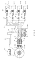
- the reference numeral 10 designates an eight cylinder internal combustion engine that has a crankshaft 12.
- Crankshaft 12 carries and drives a circular timing wheel 14 located inside the engine.
- a block wall portion 10B of engine 10 carries two variable reluctance sensors 16 and 18 that are mounted in openings formed in block portion 10B.
- the inner faces of the sensors 16 and 18 are located adjacent the outer periphery of wheel 14.
- the sensors 16 and 18 each have a pick-up coil 16A and 18A and a permanent magnet (not illustrated). As will be described in more detail hereinafter, voltage pulses are induced in the pick-up coils when wheel 14 rotates.
- the sensors are arranged such that they are spaced from one another by 27 angular degrees of the wheel 14.
- the wheel 14 has twenty-four equally angularly spaced slots which are each designated as 20. The centres of these slots are all angularly spaced by 15 degrees. Some of the slots 20 have been labelled to show this angular relationship.
- the wheel 14 has eight additional slots designated respectively as 22, 24, 26, 28, 30, 32, 34 and 36.
- the angular spacing between the centre of one of the slots 20 and the centre of the adjacent slot 24 is 7.5 degrees as is illustrated in Figure 1. The same is true for the spacing of one of the slots 20 and adjacent slot 26. This same 7.5 degree spacing pattern holds true for the other slots 22 and 28-36, as can be seen from an inspection of Figure 1.
- the slots 20 and slots 22-36 are all 3.75 degrees wide.
- the solid portions between a pair of slots are of different angular dimensions.
- the solid portions, such as portion 38 are all 11.25 degrees wide.
- the solid portions, such as portion 40 are all 3.75 degrees wide.
- the wheel 14 has an outside diameter of about 176mm and an axial thickness of about 10mm.
- pick-up coil 16A of sensor 16 is shown connected to a signal shaping circuit 42 and pick-up coil 18A of sensor 18 is shown connected to a signal shaping circuit 44.
- the voltages induced in the pick-up coils are alternating voltages and the shaping circuits convert these voltages to pulses.
- the output of circuit 42 is a train of pulses designated as A and the output of 44 is a train of pulses designated as B .
- These pulses are developed by detecting the negative going voltage zero crossings from sensors 16 and 18 which occur at the centres of the slots; that is, a pulse is developed as the centre of a slot aligns itself with the centre of a sensor.
- the pulse trains A and B that are developed as wheel 14 rotates are shown in detail in Figure 2 which will now be described.
- pulse trains A and B are shown plotted against the angular position of timing wheel 14 in degrees for 360 degrees of rotation of crankshaft 12 and wheel 14. Also shown in Figure 2 is a count of B pulses that occur between successive A pulses.
- Figure 2 has further been labelled to identify the top dead centre (TDC) angular positions of a plurality of cylinder pairs. The first number given of a cylinder pair is the firing cylinder; that is, for example, TDC 1-4 indicates that cylinder No 1 is the firing cylinder.
- Figure 2 has also been labelled SYNC POINT 2-5, SYNC POINT 7-6, SYNC POINT 3-8 AND SYNC POINT 1-4.
- the four patterns each have a unique distribution of consecutively occurring pulse counts.
- the patterns of consecutively occurring pulse counts of the B pulses between A pulses is as follows: Pattern 2-5 - 1 2 1 1 [0 1 1 2] Pattern 7-6 - 1 1 1 0 1 [0 1 2] Pattern 3-8 - 2 1 1 [0 1 1 1] Pattern 1-4 - 1 2 1 [0 1 0 1 1]
- FIG. 3 a distributorless ignition system for an eight cylinder engine is illustrated.
- the cylinder firing order for this engine is 1-2-7-3-4-5-6-8.
- This system comprises four ignition coils 50, 52, 54 and 56.
- the secondary winding of coil 50 is connected to two spark plugs 58 and 60, which are associated respectively with cylinders 1 and 4. Consequently, when a spark plug firing voltage is developed in the secondary winding of coil 50, the spark plugs associated with cylinders 1 and 4 are fired.
- coils 52, 54 and 56 are shown connected to spark plugs that respectively fire cylinders 2 and 5, 7 and 6, and 3 and 8.
- the primary windings of each ignition coil 50, 52, 54 and 56 are each shown connected to a respective primary winding coil driver D which include transistors for connecting and disconnecting a primary winding to and from the vehicle direct voltage power supply system.
- the coil drivers D are respectively connected to AND gates 62, 64, 66 and 68 which control the turn-on and turn-off of the coil drivers.
- One input of each AND gate is connected to an electronic controller 70 by lines 72, 74, 76 and 78. These lines are cylinder bank selector lines and signals on these lines enable respective AND gates.
- the signals on lines 72-78 are developed in sequential order so that only one of the AND gates is enabled at a time.
- the other inputs of AND gates 62-68 are all connected to controller 70 by a line 80.
- a signal is developed on line 80 which goes high and low. This signal causes the primary winding of a given coil to be energized and subsequently deenergized by turning a driver D on and off.
- the signal on line 80 determines the dwell time of a given coil and also the spark timing; that is, when a primary winding is deenergized, the associated spark plugs are fired.
- the signal on line 80 has a start of dwell transition (SOD) which causes a primary winding to be energized and an end of dwell transition (EOD) which causes a primary winding to be disconnected from the vehicle voltage source and a consequent firing of two spark plugs.
- SOD start of dwell transition
- EOD end of dwell transition
- the electronic controller 70 includes digital counters and digital logic networks for processing input signals and for developing output signals on lines 72-80.
- the controller 70 is connected to an electronic control module (ECM) 82 by six lines which have been labelled in Figure 3. This will be described in more detail hereinafter.
- ECM electronice control module
- the engine 10 is shown driving a camshaft 83, as well as crankshaft 12 and wheel 14.
- the camshaft 83 is driven at one-half of the crankshaft speed.
- the camshaft 83 has single protrusion 84 which passes by a variable reluctance camshaft position sensor 86.
- a single voltage pulse is developed by sensor 86 for each revolution of the camshaft. The voltage pulse occurs about 16 degrees before top dead centre of cylinder No 2 when it is in its compression stroke.
- the signal developed by camshaft sensor 86 is fed to controller 70 on line 88.
- a pulses (pulse train A ) and B pulses (pulse train B ) shown in Figure 2 are fed to electronic controller 70 on lines 90 and 92 respectively.
- the controller 70 includes a decoder section which responds to pulse trains A and B .
- This decoder when the engine is first started, enables or supplies a signal to one of the four bank selector lines 72-78 dependent upon the position of the crankshaft wheel. It does this by recognizing the pulse count pattern that represents a certain crankshaft position.
- the sync points shown in Figure 2 correspond to decoded crankshaft positions for a given cylinder pair. By way of example, if sync point 2-5 occurs first, AND gate 64 is enabled at about 37 degrees before top dead centre of cylinder pair 2-5, that is, 37 degrees before (TDC 2-5) as shown in Figure 2. The maximum angular movement of wheel 14 before a crankshaft position is recognized is about 135 degrees.
- AND gate 68 is enabled, to enable cylinder pair 3-8, after 90 degrees of crankshaft rotation following the enabling of AND gate 66.
- the AND gate 62 is enabled after 90 degrees of crankshaft rotation following the enabling of AND gate 68. This sequence continues once the engine has been started.
- the ECM 82 takes the form of a programmed microprocessor which is capable of providing spark timing information for controlling spark timing advance. It receives information that may include, for example, engine temperature and engine manifold pressure.
- the ECM 82 receives 4 voltage pulses per revolution of wheel 14. These reference pulses are applied to the ECM 82 by the REF HI line. These reference pulses are defined by a square wave that is high for 30 crankshaft degrees and low for 60 crankshaft degrees. A high-to-low transition occurs every 90 crankshaft degrees and these transitions occur at 70 degrees BTDC of every cylinder pair.
- the reference pulses are developed by counting pulses of pulse train B in controller 70.
- the ECM 82 uses this REF HI signal to compute engine speed. From this speed information and other engine operating parameters, the ECM 82 computes a spark timing advance value relative to the cylinder top dead centre (TDC).
- TDC cylinder top dead centre
- the ECM further receives 24 voltage pulses per revolution of wheel 14. This is accomplished by stripping the eight pulses of pulse train B that correspond to slots 22-36 from the pulse train. This is accomplished by an electronic stripping circuit in controller 70. This 24X signal (24 voltage pulses per revolution) is applied to ECM 82 via the line labelled 24X.
- the ECM 82 After the ECM 82 has computed a spark timing advance, it determines which one of the 24X pulses will immediately precede the desired spark advance angle. Then, using the REF HI signal as a starting point, the ECM counts 24X pulses to the proper 24X pulse. Then the ECM delays for a time period depending on the computed spark timing advance value and the engine speed. After the delay, a signal is applied to the EST line to fire a pair of spark plugs.
- Controller 70 After the ECM 82 has computed a spark timing advance, it applies a signal to the EST line at the time that a pair of spark plugs are to be fired. Controller 70 now applies an EOD signal to line 80 which causes primary winding current in one of the primary windings to be interrupted.
- the BYPASS line connecting ECM 82 and controller 70 applies a signal to controller 70 which determines whether or not the spark advance will be controlled from the output of ECM 82 or by factors internally developed by controller 70.
- controller 70 causes the spark advance to be about 10 degrees BTDC. This is accomplished by transitions of the reference pulse train.
- controller 70 develops a bypass advance that is a function only of engine speed. Bypass control is also used in the event of a failure of the ECM 82 or a failure of other lines between controller 70 and ECM 82.
- the cam pulse developed by the sensors 16, 18 is applied to ECM 82 via controller 70 by the line labelled CAM.
- the cam pulse applied to ECM 82 is for fuel injection synchronization.
- the cam pulse CAM serves another useful function. In the event that either sensor 16 or sensor 18 fails so that either pulse train A or pulse train B no longer exists, the system can still identify the proper cylinder pair to fire. As described, the cam signal pulse CAM occurs at a fixed relationship to cylinder number 2. Knowing this information, the pulses of the pulse train ( A or B ) that still exist can be counted by controller 70 from the occurrence of the cam pulse CAM to develop a proper bank selection signal for enabling one of the AND gates 62-68. In this mode of operation, the fast synchronization feature is lost since two full crankshaft revolutions may now be required to achieve synchronization.
- the wheel 14 has been described as having a plurality of slots located along its outer periphery in a certain pattern. Instead of using slots, the wheel 14 could be provided with radially projecting teeth that would have the same width as the slots and which would be disposed in the same pattern as the slots. Of course, any other suitable indicating means or mark may be used.
Landscapes
- Engineering & Computer Science (AREA)
- Chemical & Material Sciences (AREA)
- Combustion & Propulsion (AREA)
- Mechanical Engineering (AREA)
- General Engineering & Computer Science (AREA)
- Physics & Mathematics (AREA)
- Electromagnetism (AREA)
- General Physics & Mathematics (AREA)
- Ignition Installations For Internal Combustion Engines (AREA)
- Combined Controls Of Internal Combustion Engines (AREA)
- Electrical Control Of Ignition Timing (AREA)
- Transmission And Conversion Of Sensor Element Output (AREA)
Claims (6)
- Dispositif de détection de la position d'un vilebrequin d'un moteur à combustion interne comportant une roue (14) pouvant être entraínée en rotation par le vilebrequin et comportant plusieurs premiers moyens d'indication (20) espacés de manière pratiquement égale autour de la roue et plusieurs seconds moyens d'indication (22, 36) ; des premier et second détecteurs (16, 18) situés adjacents à la roue et espacés l'un de l'autre par un nombre prédéterminé de degrés angulaires par rapport à la roue, chaque détecteur étant adapté pour développer une impulsion de tension (A, B) lors du passage d'un moyen parmi les moyens d'indication à travers ceux-ci de manière à entraíner les premier et second détecteurs à développer des premier et second trains d'impulsions respectivement lors de la rotation de la roue, les impulsions de chaque train d'impulsions étant fonction du nombre et de l'écartement des premier et second moyens d'indication ; et des moyens de commande (70) destinés à recevoir les premier et second trains d'impulsions ; l'écartement des premier et second détecteurs et le nombre et l'écartement des premier et second moyens d'indication étant tels que lors de la rotation de la roue le nombre d'impulsions produit par le premier détecteur (16) entre des impulsions produites par le second détecteur (18) a un configuration prédéterminée représentative de la position angulaire du vilebrequin ; caractérisé en ce que les moyens de commande sont adaptés pour décoder le nombre d'impulsions produit par le premier détecteur entre des impulsions produites par le second détecteur pour détecter la position du vilebrequin.
- Dispositif selon la revendication 1, dans lequel les premier et second détecteurs (16, 18) et les premier et second moyens d'indication (20, 22 à 36) sont agencés de telle sorte que le premier détecteur (16) ne fournit pas plus de deux impulsions entre des impulsions consécutives du second détecteur (18).
- Dispositif selon la revendication 1 ou 2, comportant vingt-quatre premiers moyens d'indication (20) espacés de manière pratiquement égale.
- Dispositif selon la revendication 3, dans lequel les premiers moyens d'indication (16) sont espacés selon des intervalles de pratiquement 15 degrés autour de la roue (14) ; et comportent huit seconds moyens d'indication (22 à 36), chacun étant agencé entre deux premiers moyens d'indication.
- Dispositif selon l'une quelconque des revendications 1 à 4, dans lequel chacun des premier et second moyens d'indication comporte une fente (20, 22 à 36) formée dans la périphérie de la roue.
- Dispositif selon l'une quelconque des revendications 1 à 5, dans lequel la roue (14) est fixée sur le vilebrequin du moteur et est située à l'intérieur du moteur.
Applications Claiming Priority (2)
| Application Number | Priority Date | Filing Date | Title |
|---|---|---|---|
| US07/614,828 US5070727A (en) | 1990-11-16 | 1990-11-16 | Crankshaft angular position detecting apparatus |
| US614828 | 1990-11-16 |
Publications (3)
| Publication Number | Publication Date |
|---|---|
| EP0486088A2 EP0486088A2 (fr) | 1992-05-20 |
| EP0486088A3 EP0486088A3 (en) | 1993-05-12 |
| EP0486088B1 true EP0486088B1 (fr) | 1999-03-17 |
Family
ID=24462877
Family Applications (1)
| Application Number | Title | Priority Date | Filing Date |
|---|---|---|---|
| EP91202849A Expired - Lifetime EP0486088B1 (fr) | 1990-11-16 | 1991-11-01 | Appareil pour la détection de la position d'un vilebrequin |
Country Status (5)
| Country | Link |
|---|---|
| US (1) | US5070727A (fr) |
| EP (1) | EP0486088B1 (fr) |
| JP (1) | JPH079206B2 (fr) |
| CA (1) | CA2043156C (fr) |
| DE (1) | DE69131000T2 (fr) |
Cited By (1)
| Publication number | Priority date | Publication date | Assignee | Title |
|---|---|---|---|---|
| CN103245367A (zh) * | 2013-04-23 | 2013-08-14 | 联合汽车电子有限公司 | 曲轴位置检测装置及曲轴信号轮 |
Families Citing this family (35)
| Publication number | Priority date | Publication date | Assignee | Title |
|---|---|---|---|---|
| KR950009972B1 (en) * | 1991-07-04 | 1995-09-04 | Mitsubishi Electric Corp | Cylinder identifying apparatus for a multi-cylinder internal combustion engine |
| WO1993009393A1 (fr) * | 1991-11-06 | 1993-05-13 | Orbital Engine Company (Australia) Pty. Limited | Procede et appareil permettant de determiner la position d'un corps se deplaçant de maniere cyclique |
| JP2876885B2 (ja) * | 1992-04-10 | 1999-03-31 | トヨタ自動車株式会社 | 内燃機関のクランク角位置検出装置 |
| US5469054A (en) * | 1993-04-22 | 1995-11-21 | Honeywell Inc. | Position sensor with two magnetically sensitive devices and two target tracks which are sensed in combination with each other to provide a synthesized signal |
| US5570016A (en) * | 1994-06-01 | 1996-10-29 | General Motors Corporation | Method and apparatus for detecting crankshaft angular position |
| JP3327003B2 (ja) * | 1994-11-07 | 2002-09-24 | 三菱電機株式会社 | 内燃機関の気筒識別装置 |
| AUPN010194A0 (en) * | 1994-12-19 | 1995-01-19 | Deguara, Pierre | Timing device |
| US6041647A (en) * | 1996-05-28 | 2000-03-28 | Toyota Jidosha Kabushiki Kaisha | Crank angle detecting apparatus for internal combustion engine |
| WO1998012488A1 (fr) | 1996-09-23 | 1998-03-26 | S.C. Johnson Home Storage, Inc. | Sac thermoplastique refermable ayant des fermetures permanentes et des fermetures pelables |
| US5767394A (en) * | 1997-02-07 | 1998-06-16 | Ford Global Technologies, Inc. | Method and system for early cylinder identification |
| JPH10274503A (ja) * | 1997-03-25 | 1998-10-13 | Samsung Heavy Ind Co Ltd | ストロークセンシングシリンダの絶対位置検出方法 |
| US5965806A (en) * | 1997-09-30 | 1999-10-12 | Cummins Engine Company, Inc. | Engine crankshaft sensing system |
| US6035826A (en) * | 1997-09-30 | 2000-03-14 | Toyota Jidosha Kabushiki Kaisha | Crank angle detecting apparatus of internal combustion engine |
| US6131547A (en) * | 1998-02-27 | 2000-10-17 | Cummins Engine Company, Inc. | Electronic engine speed and position apparatus for camshaft gear applications |
| SE522243C2 (sv) | 1998-11-19 | 2004-01-27 | Scania Cv Ab | Anordning vid förbränningsmotorer |
| IT1310645B1 (it) * | 1999-07-28 | 2002-02-19 | Fiat Ricerche | Sistema di rilevazione delle fasi operative di un motore alternativo acombustione interna. |
| US6456063B1 (en) | 2000-11-03 | 2002-09-24 | Delphi Technologies, Inc. | Self compensating control circuit for digital magnetic sensors |
| DE10130378A1 (de) | 2001-06-23 | 2003-01-02 | Bosch Gmbh Robert | Verfahren und Vorrichtung zur Steuerung einer Brennkraftmaschine |
| SE0102374L (sv) * | 2001-06-29 | 2002-12-30 | Abb Ab | Förfarande för att bestämma ett vinkelläge hos ett svänghjul |
| DE102004060336A1 (de) * | 2004-12-15 | 2006-07-06 | Siemens Ag | Geberrad mit Rückdrehcodierung für einen Kurbelwellen- oder Nockenwellensensor |
| US7104119B1 (en) * | 2005-03-08 | 2006-09-12 | Delphi Technologies, Inc. | Method and apparatus for determining rotary position |
| JP5817732B2 (ja) * | 2009-11-06 | 2015-11-18 | セム アクティエボラグ | 点火装置制御方法およびシステム |
| JP2011202619A (ja) * | 2010-03-26 | 2011-10-13 | Keihin Corp | 電子制御装置 |
| JP2014047747A (ja) * | 2012-09-03 | 2014-03-17 | Suzuki Motor Corp | エンジン制御装置 |
| DE102013210838A1 (de) * | 2013-06-11 | 2014-12-11 | Robert Bosch Gmbh | Nockenwellenpositionsgeberrad sowie Verfahren und Vorrichtung zur Ermittlung einer Nockenwellenposition |
| DE102014203795B4 (de) * | 2014-03-03 | 2021-10-14 | Robert Bosch Gmbh | Vorrichtung zum Ermitteln der Position einer Brennkraftmaschine |
| DE102015225556A1 (de) * | 2015-12-17 | 2017-06-22 | Robert Bosch Gmbh | Nockenwellengeberrad |
| CN106285940B (zh) * | 2016-08-20 | 2018-09-11 | 重庆长安汽车股份有限公司 | 一种汽油机曲轴转速信号盘 |
| RU2739663C2 (ru) * | 2019-01-29 | 2020-12-28 | Общество с ограниченной ответственностью "АВТОКРАФТ" (ООО "АВТОКРАФТ") | Система аварийного отключения вариатора угла зажигания |
| US11131567B2 (en) | 2019-02-08 | 2021-09-28 | Honda Motor Co., Ltd. | Systems and methods for error detection in crankshaft tooth encoding |
| US11199426B2 (en) | 2019-02-08 | 2021-12-14 | Honda Motor Co., Ltd. | Systems and methods for crankshaft tooth encoding |
| US11162444B2 (en) | 2019-02-08 | 2021-11-02 | Honda Motor Co., Ltd. | Systems and methods for a crank sensor having multiple sensors and a magnetic element |
| US11181016B2 (en) | 2019-02-08 | 2021-11-23 | Honda Motor Co., Ltd. | Systems and methods for a crank sensor having multiple sensors and a magnetic element |
| US11959820B2 (en) | 2021-03-17 | 2024-04-16 | Honda Motor Co., Ltd. | Pulser plate balancing |
| CN116576903A (zh) * | 2023-04-24 | 2023-08-11 | 东风本田发动机有限公司 | 用于曲轴位置传感器的检测装置 |
Family Cites Families (9)
| Publication number | Priority date | Publication date | Assignee | Title |
|---|---|---|---|---|
| JPS6053190B2 (ja) * | 1976-10-15 | 1985-11-25 | 株式会社デンソー | 回転基準位置検出装置 |
| JPS5826339Y2 (ja) * | 1977-07-20 | 1983-06-07 | 株式会社デンソー | 回転基準位置検出装置 |
| US4262526A (en) * | 1978-07-21 | 1981-04-21 | Nippondenso Co., Ltd. | Rotational position detecting apparatus |
| JPS58133481A (ja) * | 1982-02-03 | 1983-08-09 | Nissan Motor Co Ltd | 内燃機関のタイミング検知装置 |
| GB8322886D0 (en) * | 1983-08-25 | 1983-09-28 | Lucas Ind Plc | Transducer means |
| US4697125A (en) * | 1986-03-24 | 1987-09-29 | Performance Controls, Inc. | Method and apparatus for determining shaft position and for providing commutation signals |
| US4901072A (en) * | 1988-02-17 | 1990-02-13 | Westinghouse Electric Corp. | Position detector utilizing gray code format |
| DE3809569A1 (de) * | 1988-03-22 | 1989-10-05 | Frankl & Kirchner | Positionsgeber |
| DE3816114A1 (de) * | 1988-05-11 | 1989-11-23 | Porsche Ag | Abtastvorrichtung zur drehzahlmessung an einer brennkraftmaschine |
-
1990
- 1990-11-16 US US07/614,828 patent/US5070727A/en not_active Expired - Fee Related
-
1991
- 1991-05-23 CA CA002043156A patent/CA2043156C/fr not_active Expired - Fee Related
- 1991-11-01 EP EP91202849A patent/EP0486088B1/fr not_active Expired - Lifetime
- 1991-11-01 DE DE69131000T patent/DE69131000T2/de not_active Expired - Fee Related
- 1991-11-15 JP JP3300758A patent/JPH079206B2/ja not_active Expired - Lifetime
Cited By (1)
| Publication number | Priority date | Publication date | Assignee | Title |
|---|---|---|---|---|
| CN103245367A (zh) * | 2013-04-23 | 2013-08-14 | 联合汽车电子有限公司 | 曲轴位置检测装置及曲轴信号轮 |
Also Published As
| Publication number | Publication date |
|---|---|
| JPH04265446A (ja) | 1992-09-21 |
| CA2043156C (fr) | 1996-03-26 |
| DE69131000D1 (de) | 1999-04-22 |
| DE69131000T2 (de) | 1999-07-29 |
| CA2043156A1 (fr) | 1992-05-17 |
| EP0486088A3 (en) | 1993-05-12 |
| JPH079206B2 (ja) | 1995-02-01 |
| US5070727A (en) | 1991-12-10 |
| EP0486088A2 (fr) | 1992-05-20 |
Similar Documents
| Publication | Publication Date | Title |
|---|---|---|
| EP0486088B1 (fr) | Appareil pour la détection de la position d'un vilebrequin | |
| US5469823A (en) | Sensor arrangement for rapid cylinder detection in a multi-cylinder internal combustion engine | |
| US4870587A (en) | Method of discriminating a stroke of a 4-cycle internal combustion engine | |
| KR100238735B1 (ko) | N 실린더를 갖는 내연기관의 실린더 식별용 전달장치 | |
| US4998522A (en) | Method for injecting fuel into an internal-combustion engine | |
| JP2617427B2 (ja) | 4サイクル内燃機関のシリンダにおける順次連続する燃料または点火分配の同期方法 | |
| JPH06200816A (ja) | カム軸と相対的なクランク軸の最適位相の設定方法およびシステムならびにそれによる内燃機関の作動方法 | |
| US4373486A (en) | Rotational position and velocity sensing apparatus | |
| US5079945A (en) | Crankshaft direction of rotation detecting apparatus | |
| KR20010032397A (ko) | 위상 인식 장치 | |
| US4959996A (en) | Control signal generator for an internal combustion engine | |
| US5119670A (en) | Crankshaft angular position detecting apparatus | |
| US5186144A (en) | Ignition control system with cylinder identification evaluation | |
| US4979487A (en) | Ignition controlling apparatus for multi-cylinder internal combustion engine | |
| EP0398909B1 (fr) | Appareil de determination de la vitesse, de la position angulaire et du sens de rotation d'un arbre rotatif | |
| US5778862A (en) | Ignition controller for internal combustion engine | |
| US5572973A (en) | Method for cylinder identification in an internal combustion engine when idling | |
| EP0506165B1 (fr) | Système de commande de l'instant d'allumage | |
| US5699769A (en) | Controller for four-stroke cycle internal-combustion engine | |
| JP2629022B2 (ja) | 内燃機関の点火起動装置 | |
| EP0375635B1 (fr) | Méthode et système de commande de l'allumage dans les moteurs à combustion interne, particulièrement les moteurs équipés d'une bobine d'allumage par cylindre | |
| US4498444A (en) | Method of controlling engine | |
| EP1160436A2 (fr) | Dispositif et méthode d'identification de cylindre pour moteur à combustion interne | |
| EP1334267B1 (fr) | Moteur sans cames presentant une indication de la position du vilebrequin | |
| EP0704621B1 (fr) | Dispositif de synchronisation sans un capteur de position de l'arbre à cames pour un moteur à combustion interne |
Legal Events
| Date | Code | Title | Description |
|---|---|---|---|
| PUAI | Public reference made under article 153(3) epc to a published international application that has entered the european phase |
Free format text: ORIGINAL CODE: 0009012 |
|
| AK | Designated contracting states |
Kind code of ref document: A2 Designated state(s): DE FR GB |
|
| PUAL | Search report despatched |
Free format text: ORIGINAL CODE: 0009013 |
|
| AK | Designated contracting states |
Kind code of ref document: A3 Designated state(s): DE FR GB |
|
| 17P | Request for examination filed |
Effective date: 19930706 |
|
| 17Q | First examination report despatched |
Effective date: 19941117 |
|
| GRAG | Despatch of communication of intention to grant |
Free format text: ORIGINAL CODE: EPIDOS AGRA |
|
| GRAG | Despatch of communication of intention to grant |
Free format text: ORIGINAL CODE: EPIDOS AGRA |
|
| GRAH | Despatch of communication of intention to grant a patent |
Free format text: ORIGINAL CODE: EPIDOS IGRA |
|
| GRAH | Despatch of communication of intention to grant a patent |
Free format text: ORIGINAL CODE: EPIDOS IGRA |
|
| GRAA | (expected) grant |
Free format text: ORIGINAL CODE: 0009210 |
|
| AK | Designated contracting states |
Kind code of ref document: B1 Designated state(s): DE FR GB |
|
| REF | Corresponds to: |
Ref document number: 69131000 Country of ref document: DE Date of ref document: 19990422 |
|
| ET | Fr: translation filed | ||
| PLBE | No opposition filed within time limit |
Free format text: ORIGINAL CODE: 0009261 |
|
| STAA | Information on the status of an ep patent application or granted ep patent |
Free format text: STATUS: NO OPPOSITION FILED WITHIN TIME LIMIT |
|
| 26N | No opposition filed | ||
| PGFP | Annual fee paid to national office [announced via postgrant information from national office to epo] |
Ref country code: GB Payment date: 20001109 Year of fee payment: 10 |
|
| PGFP | Annual fee paid to national office [announced via postgrant information from national office to epo] |
Ref country code: FR Payment date: 20001116 Year of fee payment: 10 |
|
| PGFP | Annual fee paid to national office [announced via postgrant information from national office to epo] |
Ref country code: DE Payment date: 20001228 Year of fee payment: 10 |
|
| PG25 | Lapsed in a contracting state [announced via postgrant information from national office to epo] |
Ref country code: GB Free format text: LAPSE BECAUSE OF NON-PAYMENT OF DUE FEES Effective date: 20011101 |
|
| REG | Reference to a national code |
Ref country code: GB Ref legal event code: IF02 |
|
| GBPC | Gb: european patent ceased through non-payment of renewal fee |
Effective date: 20011101 |
|
| PG25 | Lapsed in a contracting state [announced via postgrant information from national office to epo] |
Ref country code: DE Free format text: LAPSE BECAUSE OF NON-PAYMENT OF DUE FEES Effective date: 20020702 |
|
| PG25 | Lapsed in a contracting state [announced via postgrant information from national office to epo] |
Ref country code: FR Free format text: LAPSE BECAUSE OF NON-PAYMENT OF DUE FEES Effective date: 20020730 |
|
| REG | Reference to a national code |
Ref country code: FR Ref legal event code: ST |
|
| REG | Reference to a national code |
Ref country code: FR Ref legal event code: ST |