EP1160436A2 - Dispositif et méthode d'identification de cylindre pour moteur à combustion interne - Google Patents
Dispositif et méthode d'identification de cylindre pour moteur à combustion interne Download PDFInfo
- Publication number
- EP1160436A2 EP1160436A2 EP01113294A EP01113294A EP1160436A2 EP 1160436 A2 EP1160436 A2 EP 1160436A2 EP 01113294 A EP01113294 A EP 01113294A EP 01113294 A EP01113294 A EP 01113294A EP 1160436 A2 EP1160436 A2 EP 1160436A2
- Authority
- EP
- European Patent Office
- Prior art keywords
- cylinder discrimination
- crank angle
- signal
- count value
- signals
- Prior art date
- Legal status (The legal status is an assumption and is not a legal conclusion. Google has not performed a legal analysis and makes no representation as to the accuracy of the status listed.)
- Granted
Links
Images







Classifications
-
- F—MECHANICAL ENGINEERING; LIGHTING; HEATING; WEAPONS; BLASTING
- F02—COMBUSTION ENGINES; HOT-GAS OR COMBUSTION-PRODUCT ENGINE PLANTS
- F02D—CONTROLLING COMBUSTION ENGINES
- F02D41/00—Electrical control of supply of combustible mixture or its constituents
- F02D41/009—Electrical control of supply of combustible mixture or its constituents using means for generating position or synchronisation signals
-
- F—MECHANICAL ENGINEERING; LIGHTING; HEATING; WEAPONS; BLASTING
- F02—COMBUSTION ENGINES; HOT-GAS OR COMBUSTION-PRODUCT ENGINE PLANTS
- F02D—CONTROLLING COMBUSTION ENGINES
- F02D41/00—Electrical control of supply of combustible mixture or its constituents
- F02D41/02—Circuit arrangements for generating control signals
- F02D41/04—Introducing corrections for particular operating conditions
- F02D41/06—Introducing corrections for particular operating conditions for engine starting or warming up
Definitions
- the present invention relates to a technique for discriminating cylinders at a predetermined stroke of an engine, and particularly relates to a technique for discriminating cylinders as soon as possible after start of cranking.
- the present invention has been achieved taking into consideration the above mentioned problems and has an object to enable cylinder discrimination to be performed as soon as possible after a cranking start.
- cylinder discrimination can be performed as soon as possible after a cranking start.
- the present invention is constituted as follows.
- a crank angle signal is output, at a crank angle position for each unit crank angle using a reference crank angle position for each stroke phase difference between cylinders as a reference, from a sensor mounted to a member interlocked with a crankshaft in synchronization with the rotation of the crankshaft.
- a counter or a memory counts the number of crank angle signals output after a cranking start and holds a count value of each time the cylinder discrimination signal is output.
- a computation processing unit compares the count value of the number of crank angle signal outputs at a first cylinder discrimination timing with the past count value held, and detects the number of cylinder discrimination signals output during the predetermined crank angle period, to perform first cylinder discrimination after the cranking start based on the number of the cylinder discrimination signals.
- the count value of the number of the crank angle signal outputs is held.
- the count value which has a difference within a certain value to the count value in the cylinder discrimination timing can be judged to have been obtained because the cylinder discrimination signal is output during the predetermined crank angle period.
- the number of cylinder discrimination signals output during the predetermined crank angle period is detected so that cylinder discrimination can be performed.
- the cylinder discrimination can be accurately performed, thereby enabling to improve the engine start performance and the exhaust emission performance by quick cylinder discrimination.
- the constitution may be such that, as the past count values, a plurality of count values including the latest renewed value and the values prior to the latest renewed value are held, and based on a value obtained by subtracting each past count value from the count value at the first cylinder discrimination timing, the number of the cylinder discrimination signals output during the predetermined crank angle period is detected.
- the cylinder discrimination can be performed by detecting the number of cylinder discrimination signals output during the predetermined crank angle period, based on the value obtained by subtracting each past count value from the count value at the first cylinder discrimination timing.
- a detection of the reference crank angle position may be prohibited until a predetermined number of the crank angle signals after the cranking start is output.
- the cylinder discrimination at the cylinder discrimination timing is prohibited.
- FIG. 1 is a diagram showing a system structure of an in-line four cylinder engine according to a first embodiment of the present invention
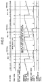
- FIG. 2 is a time chart showing output characteristics of a crank angle sensor and a cam sensor, and cylinder discrimination in a normal state based on the output characteristics in the first embodiment
- FIG. 3 is a time chart showing first cylinder discrimination after a cranking start in the first embodiment
- FIG. 4 is a time chart showing a mask processing at the first cylinder discrimination according to the first embodiment
- FIG. 5 is a flowchart showing an interruption processing routine based on an output of cylinder discrimination signal Phase according to the first embodiment
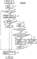
- FIG. 6 is a flowchart showing an interruption processing routine based on an output of crank angle signal POS according to the first embodiment
- FIG. 7 is a flowchart showing a first cylinder discrimination processing routine according to the first embodiment
- FIG. 8 is a diagram showing a system structure of a V-type six cylinder engine according to a second embodiment of the present invention.
- FIG. 9 is a time chart showing output characteristics of a left side cam sensor, a right side cam sensor, and a crank angle sensor, and cylinder discrimination in a normal state based on the output characteristics in the second embodiment;
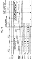
- FIG. 10 is a flowchart showing first cylinder discrimination according to the second embodiment
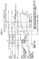
- FIG. 11 is a time chart showing a mask processing at the first cylinder discrimination according to the second embodiment
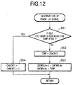
- FIG. 12 is a flowchart showing an interruption processing routine of a cylinder discrimination signal on the left bank according to the second embodiment
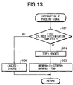
- FIG. 13 is a flow chart showing an interruption processing routine of a cylinder discrimination signal on the right bank according to the second embodiment of the present invention.
- FIG. 14 is a flow chart showing an interruption processing routine of a crank angle signal according to the second embodiment
- FIG. 15 is a flowchart showing a first cylinder discrimination processing routine according to the second embodiment
- an in-line four cylinder engine 1 is equipped with an intake side camshaft 2 and an exhaust side camshaft 3.
- Signal plates 4, 5 are axially supported, respectively, on each axis of the intake side camshaft 2 and the exhaust side camshaft 3.
- magnetic cam sensors 6, 7 for detecting projections (not shown) formed at the signal plates 4, 5, respectively, to output cylinder discrimination signals Phase, respectively.
- a magnetic crank angle sensor 9 is provided for detecting projections (not shown) formed at a signal plate 8 mounted to a crank pulley, to output a position signal POS for each unit angle (10°).
- a control unit 10 receives detection signals from the cam sensors 6, 7 and the crank angle sensor 9. Based on these detection signals, the control unit 10 performs cylinder discrimination to control fuel injection and/or an ignition in the engine. Further, there is provided a valve timing device (hereinafter, to be referred as VTC) for changing a valve timing while keeping an operation angle to be constant, by changing a rotation phase of the camshaft relative to a crankshaft so as to detect the rotation phase based on the detection signals, thereby feedback controlling the rotation phase.
- VTC valve timing device
- a position signal POS to be output from the crank angle sensor 9 is output at each predetermined unit crank angle (10° in this embodiment), and at each 180° degree equivalent to a stroke phase difference between cylinders, there is no signal for the position signal. Then, a reference crank angle position is detected by detecting a position of no signal, and a crank angle position for each unit crank angle is detected by measuring the number of position signals POS output from the reference crank angle position with a counter CRACNT.
- cylinder discrimination signals Phase to be output from the cam sensors 6, 7 are output at each predetermined crank angle (30° in this embodiment) by the number equal to the cylinder number for each cylinder.
- the number of cylinder discrimination signals Phase at each crank angle period 180° (ATCD 30° for each cylinder in this embodiment) equivalent to a cylinder stroke phase difference to be detected by the crank angle sensor 9 is directly counted (Step 4 in FIG. 5) to discriminate a cylinder corresponding to the counted number (Step 20 in FIG. 6).
- an ignition order is #1 - #3 - #4 - #2
- the counted number of the cylinder discrimination signals Phase by the counter CAMCNT is 1, the next ignition cylinder is discriminated to be #3.
- next ignition cylinder is discriminated to be #4
- the next ignition cylinder is discriminated to be #2
- the next ignition cylinder is discriminated to be #1.
- first cylinder discrimination after a cranking start is performed as follows (refer to FIG. 3).
- a main counter CRACNT0 counts the number of position signals POS (crank angle signal) to be output after the cranking start (Step 11 in FIG. 6).
- a first sub-counter CMTMPn renews a value thereof to a count value of the main counter CRACNT0 at that time, to hold (Steps 2, 3 in FIG. 5).
- the cylinder discrimination is performed based on a value obtained by subtracting the count value of each sub-counter CMTMPn ⁇ CMTMP (n-3) from the count value of the main counter CRACNT0.
- a first cylinder discrimination signal Phase is output, so that the count value 2 of the main counter CRACNT0 is held to the first sub-counter CMTMPn, and in turn each time second, third cylinder discrimination signal is output, the count value is renewed to the count value 3, 6 of the main counter CRACNT0 at that time, to be held.
- the first sub-counter CMTMPn which has been holding the count value 6 is renewed the counter value thereof to the count value 18 of the main counter CRACNT0, to hold, and in turn each time the second to four cylinder discrimination signals Phase is output, the count value is renewed to the count values 19, 22, and 24, to be held.
- the second sub-counter CMTMP(n-1) holds the count value 0 of the prior first sub-counter CMTMPn, and each time the second, third cylinder discrimination signals Phase is output, the second sub-counter CMTMP(n-1) renews the count value thereof to the count values 2, 3 of the first sub-counter CMTMPn, to hold, and renews the count value thereof to the count values 6, 18,19, and 22 each time four cylinder discrimination signals for the next cylinder discrimination is output .
- the third sub-counter CMTMP(n-2) renews the count value thereof from 0 to the count value 2 of the prior second sub-counter CMTMP(n-1), and each time four cylinder discrimination signals Phase for the next cylinder discrimination is output, the third sub-counter CMTMP(n-2), in turn, renews the count value thereof to the count values 3, 6, 18, and 19, to hold.
- the fourth sub-counter CMTMP(n-3) renews the count value thereof from 0 to the count value 2 of the prior third sub-counter CMTMP(n-2), to hold, and in turn renews to the count values 3, 6, and 18.
- the first cylinder discrimination is performed at a second cylinder discrimination timing after the cranking start (detect the second cylinder discrimination timing as the first discrimination timing).
- the cylinder discrimination according to the present invention is performed based on the number of cylinder discrimination signals Phase between two cylinder discrimination timings.
- the first cylinder discrimination timing is not detected based on the reference crank angle position.
- a cylinder discrimination method in a normal state second time and thereafter
- the second cylinder discrimination timing is detected as the first cylinder discrimination timing
- the cylinder discrimination becomes possible.
- an inaccurate detection of the reference crank angle position at the unstable engine rotation is prohibited, and also a mask processing to prohibit the detection of the reference crank angle position during a predetermined period after the cranking start is performed so that the cylinder discrimination can be accurately performed when the first cylinder discrimination timing is detected based on the first reference crank angle position detection.
- FIG. 4 shows the mask processing.
- a concrete cylinder discrimination timing is set to 30° after a top dead center (ATDC)
- ADC top dead center
- the reference crank angle position (a first position after a period of no crank angle signal) is set to 40° before the top dead center (BTDC)
- the number of position signals POS output during a period from the first reference crank angle position detection to the first cylinder discrimination timing detection is 7, and the number of the position signals POS output during the crank angle period (180°) equivalent to the cylinder stroke phase difference is 16
- the number (number of masks) of the position signals POS output to prohibit the detection of the reference crank angle position after the cranking start is determined in accordance with the following equation, setting a tolerance as 1.
- the detection of the reference crank angle position based on a cycle ratio of the position signals POS is prohibited until the count value of the position signals POS by the main counter CRACNT0 after the cranking start reaches 10 (judgment at Step 12 in FIG. 6 is No).
- the detection of the reference crank angle position is started after the count value becomes 10 or more (judgment at Step 12 is YES), and when a predetermined number (7) of the output position signals POS is detected after the detection of the first reference crank angle position, the first discrimination timing is detected (Steps 13, 14 ⁇ 16, 17 ⁇ 18, in FIG. 6).
- the count values of the first to fourth sub-counters CMTMPn - CMTMP (n-1) are subtracted, respectively, from the count value of the main counter CRACNT0 at the time of when the first cylinder discrimination timing is detected, and it is judged whether or not each of these four subtracted values is equal to a predetermined value 16 or less.
- the predetermined value 16 is the number of the position signals POS output during the crank angle period in which the cylinder discrimination is possible based on the number of the cylinder discrimination signals output during the crank angle period equivalent to the cylinder stroke phase difference. Accordingly, when the subtracted value is the predetermined value 16 or less, the count value of the corresponding sub-counter CMTMP is renewed by the output of the cylinder discrimination signal Phase during the predetermined crank angle period.
- a V-type six cylinder engine 1 has an intake side camshaft 2a and an exhaust side camshaft 3a on one bank and on the other bank an intake side camshaft 2b and an exhaust side camshaft 3b.
- signal plates 4, 5 are axially supported, respectively, on each axis of the intake side camshaft 2a and the exhaust side camshaft 2a on the left and right banks.
- magnetic type left side cam sensor 6 and right side cam sensor 7 for detecting projections (not shown) formed at the signal plates 4, 5, respectively, to output cylinder discrimination signals PhaseLH and PhaseRH, respectively.
- the left side cam sensor 6 and the right side cam sensor 7 may be disposed on the exhaust side camshafts 3a and 3b on the left and right banks, respectively. Further, the left side cam sensor 6 and the right side cam sensor 7 may be disposed on the intake side camshaft 2a and the exhaust side camshaft 3a on one bank.
- crank pulley in the same as the first embodiment, is provided with a magnet crank angle sensor 9 for detecting projections (not shown) formed at a signal plate 8, to output a position signal POS for each unit angle (10°).
- an intake valve timing control device and an exhaust valve timing control device for changing valve timings while keeping an operation angle to be constant, by changing rotation phases of the intake and exhaust side camshafts relative to a crankshaft.
- a control unit 10 performs an engine control while performing cylinder discrimination based on detection signals from the above described sensors, and detects rotation phases of the intake side camshafts based on the detection signals to feedback control the rotation phases.
- the rotation phases of the exhaust side camshafts are detected based on detection signals by other sensors (not shown in the figure).
- a cylinder discrimination timing is set to be BTDC 30°, and the cylinder discrimination is performed by the combination of the number of cylinder discrimination signals PhaseLH and the number of cylinder discrimination signals RH output between the cylinder discrimination timings. Specifically, when a count value of the cylinder discrimination signal PhaseLH counted by a counter CAMCNT1 is 0, and a count value of the cylinder discrimination signal PhaseRH counted by a counter CAMCNT2 is 1, # 2 cylinder is discriminated. In the same way, when the count value of the cylinder discrimination signal PhaseLH is 2, and the count value of the cylinder discrimination signal PhaseRH is 2, # 3 cylinder is discriminated.
- first cylinder discrimination according to the present invention is performed in the sama way with the first embodiment.
- a left side first sub-counter CMTMPHL(n) which renews and holds a count value of the position signal POS by a main counter CRACNT0
- a left side second sub-counter CMTMPLH(n-1) which renews and holds a prior count value of the left side first sub-counter CMTMPLH(n)
- CMTMPRH(n) which renews and holds a count value of the position signal POS by the main counter CRACNT0
- CMTMPRH(n-1) which renews and holds a prior count value of the right side first sub-counter CMTMPRH(n)
- a mask processing is carried out in the same way as the first embodiment (refer to FIG. 11). Since the engine is a six cylinder engine, a cylinder stroke phase difference is 120°, the number of the position signals output during this period is 10 and the number of the position signals POS output during a period from the reference crank angle position (BTDC 60°) to the cylinder discrimination timing (BTDC 30°) is 3. Therefore, when a tolerance is set as 1, the number (number of masks) of the output position signals POS prohibiting the detection of the reference crank angle position after the cranking start is determined in accordance with the following equation.
- the count values of the left side first sub-counter CMTMPLH(n), the left side second sub-counter CMTMPLH(n-1), the right side first sub-counter CMTMPRH(n), and the right side second sub-counter CMTMPRH(n-1) are subtracted, respectively, from the count value of the main counter CRACNT0, and it is judged whether or not each of these four subtracted values is equal to a predetermined value 10 or less (the number of the position signals output during the crank angle period equivalent to the cylinder stroke phase difference 120°) ( Steps 91, 93, 96, 98 in FIG. 15 ).
- the subtracted value is the predetermined value 10 or less
- the count value of the corresponding sub-counter CMTMP is renewed by the output of the cylinder discrimination signal Phase during the predetermined crank angle period.
- the subtracted value of the left side first sub-counter CMTMPLH(n) from the main counter CRACNT0 is 11 or more
- the subtracted value of the left side second sub-counter CMTMPLH(n-1) from the main counter CRACNT0 becomes 11 or more. It means that the cylinder discrimination signal PhaseLH has not been output during the predetermined crank angle period, therefore, the count value of the counter CAMCNT1 is set to 0 (Step 92 in FIG. 15).
- the count value of the counter CAMCNT1 is set to 1 (Step 94 in FIG.
- the count value of the counter CAMCNT2 is set to 0 (Step 97 in FIG. 15).
- the count value of the counter CAMCNT2 is set to 1 (Step 99 in FIG. 15), and further, when the subtracted value of the right side second sub-counter CMTMPRH(n-1) is also 10 or less, the count value of the counter CAMCNT2 is set to 2 (Step 101 in FIG. 15).
- the cylinder discrimination is performed based on the combination of the values of the counters CAMCNT1 and CAMCNT2.
- the mask processing to prohibit the reference crank angle position detection is carried out until the predetermined number of the position signals POS are output.
- the constitution may be such that the detection of the reference crank angle position is not prohibited for the time being, and when the count value of the position signals POS at detection of cylinder discrimination timing based on the detected reference crank angle position does not reach the count value of when the crank angle period equivalent to the cylinder stroke phase difference has elapsed, the cylinder discrimination is prohibited.
Landscapes
- Engineering & Computer Science (AREA)
- Chemical & Material Sciences (AREA)
- Combustion & Propulsion (AREA)
- Mechanical Engineering (AREA)
- General Engineering & Computer Science (AREA)
- Combined Controls Of Internal Combustion Engines (AREA)
- Output Control And Ontrol Of Special Type Engine (AREA)
Applications Claiming Priority (2)
| Application Number | Priority Date | Filing Date | Title |
|---|---|---|---|
| JP2000165669 | 2000-06-02 | ||
| JP2000165669A JP3766260B2 (ja) | 2000-06-02 | 2000-06-02 | エンジンの気筒判別装置 |
Publications (3)
| Publication Number | Publication Date |
|---|---|
| EP1160436A2 true EP1160436A2 (fr) | 2001-12-05 |
| EP1160436A3 EP1160436A3 (fr) | 2003-10-22 |
| EP1160436B1 EP1160436B1 (fr) | 2005-04-20 |
Family
ID=18669109
Family Applications (1)
| Application Number | Title | Priority Date | Filing Date |
|---|---|---|---|
| EP01113294A Expired - Lifetime EP1160436B1 (fr) | 2000-06-02 | 2001-05-31 | Dispositif et méthode d'identification de cylindre pour moteur à combustion interne |
Country Status (4)
| Country | Link |
|---|---|
| US (1) | US6626030B2 (fr) |
| EP (1) | EP1160436B1 (fr) |
| JP (1) | JP3766260B2 (fr) |
| DE (1) | DE60110151T2 (fr) |
Families Citing this family (9)
| Publication number | Priority date | Publication date | Assignee | Title |
|---|---|---|---|---|
| DE10108055C1 (de) * | 2001-02-20 | 2002-08-08 | Siemens Ag | Verfahren zum Steuern einer Brennkraftmaschine |
| JP3794485B2 (ja) | 2002-06-26 | 2006-07-05 | 三菱電機株式会社 | 内燃機関の気筒判別装置 |
| US7373928B2 (en) * | 2006-05-31 | 2008-05-20 | Joseph Thomas | Method for starting a direct injection engine |
| US7966869B2 (en) * | 2007-07-06 | 2011-06-28 | Hitachi, Ltd. | Apparatus and method for detecting cam phase of engine |
| WO2012120632A1 (fr) * | 2011-03-08 | 2012-09-13 | トヨタ自動車株式会社 | Dispositif et procédé de commande pour moteur, dispositif de démarrage de moteur et véhicule |
| JP5221711B2 (ja) | 2011-06-10 | 2013-06-26 | 三菱電機株式会社 | 内燃機関自動停止再始動制御装置 |
| JP6119415B2 (ja) * | 2013-05-15 | 2017-04-26 | 株式会社デンソー | 可変動弁機構の弁開閉時期検出装置、及び可変動弁機構の制御装置 |
| CN105841964A (zh) * | 2016-03-23 | 2016-08-10 | 潍柴动力股份有限公司 | 一种柴油机凸轮轴、挺柱可靠性试验装置 |
| CN115355096B (zh) * | 2022-08-03 | 2023-11-28 | 中车大连机车车辆有限公司 | 一种发动机快速启动同步控制方法 |
Family Cites Families (8)
| Publication number | Priority date | Publication date | Assignee | Title |
|---|---|---|---|---|
| JPH05106500A (ja) * | 1991-10-21 | 1993-04-27 | Nissan Motor Co Ltd | 内燃機関の気筒判別方法および気筒判別装置 |
| US5808186A (en) * | 1992-06-09 | 1998-09-15 | Mitsubishi Jidosha Kogyo Kabushiki Kaisha | Method for detecting misfire by fluctuation in crankshaft rotation |
| GB2270177B (en) * | 1992-08-31 | 1995-11-22 | Silicon Systems Inc | Programmable system for the synchronization of an electronic angular position indicator |
| JP3379271B2 (ja) * | 1995-03-28 | 2003-02-24 | 株式会社デンソー | エンジンの気筒判別装置 |
| US5979413A (en) * | 1996-03-01 | 1999-11-09 | Mitsubishi Jidosha Kogyo Kabushiki Kaisha | Cylinder judging device for internal combustion engine |
| JP3680492B2 (ja) * | 1997-06-03 | 2005-08-10 | 日産自動車株式会社 | 内燃機関の制御装置 |
| US6302085B1 (en) * | 1998-03-02 | 2001-10-16 | Unisia Sec's Corporation | Apparatus and method for detecting crank angle of engine |
| JP2000199445A (ja) * | 1998-12-28 | 2000-07-18 | Hitachi Ltd | エンジン駆動モ―タ制御装置 |
-
2000
- 2000-06-02 JP JP2000165669A patent/JP3766260B2/ja not_active Expired - Lifetime
-
2001
- 2001-05-29 US US09/865,730 patent/US6626030B2/en not_active Expired - Lifetime
- 2001-05-31 EP EP01113294A patent/EP1160436B1/fr not_active Expired - Lifetime
- 2001-05-31 DE DE60110151T patent/DE60110151T2/de not_active Expired - Lifetime
Also Published As
| Publication number | Publication date |
|---|---|
| DE60110151D1 (de) | 2005-05-25 |
| JP3766260B2 (ja) | 2006-04-12 |
| JP2001342887A (ja) | 2001-12-14 |
| EP1160436A3 (fr) | 2003-10-22 |
| US6626030B2 (en) | 2003-09-30 |
| DE60110151T2 (de) | 2005-09-22 |
| EP1160436B1 (fr) | 2005-04-20 |
| US20020007244A1 (en) | 2002-01-17 |
Similar Documents
| Publication | Publication Date | Title |
|---|---|---|
| US5548995A (en) | Method and apparatus for detecting the angular position of a variable position camshaft | |
| US5469823A (en) | Sensor arrangement for rapid cylinder detection in a multi-cylinder internal combustion engine | |
| US4827886A (en) | Crank angle detecting system for an internal combustion engine | |
| US7013719B2 (en) | Device for identifying crank angle of engine | |
| US7409936B2 (en) | Cam angle detecting apparatus, and cam phase detecting apparatus for internal combustion engine and cam phase detecting method thereof | |
| EP1160436B1 (fr) | Dispositif et méthode d'identification de cylindre pour moteur à combustion interne | |
| KR20010032397A (ko) | 위상 인식 장치 | |
| US4959996A (en) | Control signal generator for an internal combustion engine | |
| US6505128B1 (en) | Apparatus and method for judging cylinders of an engine | |
| US6874359B2 (en) | Control apparatus and control method of engine | |
| US6483312B2 (en) | Cylinder discrimination device and cylinder discrimination method of engine | |
| EP1736657B1 (fr) | Dispositif et méthode pour déterminer la position d'un piston d'un moteur | |
| US8490599B2 (en) | Abnormality determination apparatus and abnormality determination method for internal combustion engine | |
| JPH06213052A (ja) | 4サイクルエンジンの制御装置 | |
| US6223722B1 (en) | Apparatus and method for controlling an ignition timing in an internal combustion engine | |
| JPH08121299A (ja) | 独立点火方法 | |
| JPH0649878Y2 (ja) | 多気筒内燃機関の気筒判別装置 | |
| JP2006070789A (ja) | 可変バルブタイミング装置 | |
| EP1128047A2 (fr) | Système et méthode d'identification de cylindre d'un moteur à explosion | |
| JP2858286B2 (ja) | 内燃機関の気筒判別装置 | |
| JP3782884B2 (ja) | エンジンのクランク角検出装置 | |
| JP3764023B2 (ja) | エンジンの気筒判別装置 | |
| JPH0510227A (ja) | 内燃機関の気筒判別装置 | |
| JPH11343919A (ja) | エンジンの気筒判別装置 | |
| JPH10274090A (ja) | エンジン制御装置 |
Legal Events
| Date | Code | Title | Description |
|---|---|---|---|
| PUAI | Public reference made under article 153(3) epc to a published international application that has entered the european phase |
Free format text: ORIGINAL CODE: 0009012 |
|
| AK | Designated contracting states |
Kind code of ref document: A2 Designated state(s): AT BE CH CY DE DK ES FI FR GB GR IE IT LI LU MC NL PT SE TR |
|
| AX | Request for extension of the european patent |
Free format text: AL;LT;LV;MK;RO;SI |
|
| PUAL | Search report despatched |
Free format text: ORIGINAL CODE: 0009013 |
|
| AK | Designated contracting states |
Kind code of ref document: A3 Designated state(s): AT BE CH CY DE DK ES FI FR GB GR IE IT LI LU MC NL PT SE TR |
|
| AX | Request for extension of the european patent |
Extension state: AL LT LV MK RO SI |
|
| 17P | Request for examination filed |
Effective date: 20040416 |
|
| AKX | Designation fees paid |
Designated state(s): DE FR |
|
| GRAP | Despatch of communication of intention to grant a patent |
Free format text: ORIGINAL CODE: EPIDOSNIGR1 |
|
| GRAS | Grant fee paid |
Free format text: ORIGINAL CODE: EPIDOSNIGR3 |
|
| GRAA | (expected) grant |
Free format text: ORIGINAL CODE: 0009210 |
|
| RAP1 | Party data changed (applicant data changed or rights of an application transferred) |
Owner name: HITACHI, LTD. |
|
| AK | Designated contracting states |
Kind code of ref document: B1 Designated state(s): DE FR |
|
| REG | Reference to a national code |
Ref country code: IE Ref legal event code: FG4D |
|
| REF | Corresponds to: |
Ref document number: 60110151 Country of ref document: DE Date of ref document: 20050525 Kind code of ref document: P |
|
| PLBE | No opposition filed within time limit |
Free format text: ORIGINAL CODE: 0009261 |
|
| STAA | Information on the status of an ep patent application or granted ep patent |
Free format text: STATUS: NO OPPOSITION FILED WITHIN TIME LIMIT |
|
| ET | Fr: translation filed | ||
| 26N | No opposition filed |
Effective date: 20060123 |
|
| REG | Reference to a national code |
Ref country code: FR Ref legal event code: PLFP Year of fee payment: 16 |
|
| REG | Reference to a national code |
Ref country code: FR Ref legal event code: PLFP Year of fee payment: 17 |
|
| REG | Reference to a national code |
Ref country code: FR Ref legal event code: PLFP Year of fee payment: 18 |
|
| PGFP | Annual fee paid to national office [announced via postgrant information from national office to epo] |
Ref country code: FR Payment date: 20200414 Year of fee payment: 20 Ref country code: DE Payment date: 20200519 Year of fee payment: 20 |
|
| REG | Reference to a national code |
Ref country code: DE Ref legal event code: R071 Ref document number: 60110151 Country of ref document: DE |