EP0486096A1 - Unterdrückung des Überfaltungsartefaktes in Puls-Dopplersystemen - Google Patents
Unterdrückung des Überfaltungsartefaktes in Puls-Dopplersystemen Download PDFInfo
- Publication number
- EP0486096A1 EP0486096A1 EP91202895A EP91202895A EP0486096A1 EP 0486096 A1 EP0486096 A1 EP 0486096A1 EP 91202895 A EP91202895 A EP 91202895A EP 91202895 A EP91202895 A EP 91202895A EP 0486096 A1 EP0486096 A1 EP 0486096A1
- Authority
- EP
- European Patent Office
- Prior art keywords
- spectrum
- mean
- velocity
- spectral
- data
- Prior art date
- Legal status (The legal status is an assumption and is not a legal conclusion. Google has not performed a legal analysis and makes no representation as to the accuracy of the status listed.)
- Granted
Links
- 230000001629 suppression Effects 0.000 title description 2
- 238000001228 spectrum Methods 0.000 claims abstract description 61
- 230000003595 spectral effect Effects 0.000 claims abstract description 31
- 238000002604 ultrasonography Methods 0.000 claims description 17
- 238000000034 method Methods 0.000 claims description 16
- 238000004422 calculation algorithm Methods 0.000 abstract description 4
- 239000011159 matrix material Substances 0.000 description 8
- 239000008280 blood Substances 0.000 description 7
- 210000004369 blood Anatomy 0.000 description 7
- 238000002592 echocardiography Methods 0.000 description 6
- 230000006870 function Effects 0.000 description 5
- 230000017531 blood circulation Effects 0.000 description 3
- 239000013598 vector Substances 0.000 description 3
- 241001465754 Metazoa Species 0.000 description 2
- 238000004364 calculation method Methods 0.000 description 2
- 230000000737 periodic effect Effects 0.000 description 2
- 210000001367 artery Anatomy 0.000 description 1
- 210000004204 blood vessel Anatomy 0.000 description 1
- 238000004590 computer program Methods 0.000 description 1
- 239000000284 extract Substances 0.000 description 1
- 238000005259 measurement Methods 0.000 description 1
Images

Classifications
-
- G—PHYSICS
- G01—MEASURING; TESTING
- G01S—RADIO DIRECTION-FINDING; RADIO NAVIGATION; DETERMINING DISTANCE OR VELOCITY BY USE OF RADIO WAVES; LOCATING OR PRESENCE-DETECTING BY USE OF THE REFLECTION OR RERADIATION OF RADIO WAVES; ANALOGOUS ARRANGEMENTS USING OTHER WAVES
- G01S15/00—Systems using the reflection or reradiation of acoustic waves, e.g. sonar systems
- G01S15/02—Systems using the reflection or reradiation of acoustic waves, e.g. sonar systems using reflection of acoustic waves
- G01S15/50—Systems of measurement, based on relative movement of the target
- G01S15/58—Velocity or trajectory determination systems; Sense-of-movement determination systems
- G01S15/582—Velocity or trajectory determination systems; Sense-of-movement determination systems using transmission of interrupted pulse-modulated waves and based upon the Doppler effect resulting from movement of targets
- G01S15/584—Velocity or trajectory determination systems; Sense-of-movement determination systems using transmission of interrupted pulse-modulated waves and based upon the Doppler effect resulting from movement of targets with measures taken for suppressing velocity ambiguities, i.e. anti-aliasing
-
- G—PHYSICS
- G01—MEASURING; TESTING
- G01P—MEASURING LINEAR OR ANGULAR SPEED, ACCELERATION, DECELERATION, OR SHOCK; INDICATING PRESENCE, ABSENCE, OR DIRECTION, OF MOVEMENT
- G01P5/00—Measuring speed of fluids, e.g. of air stream; Measuring speed of bodies relative to fluids, e.g. of ship, of aircraft
- G01P5/24—Measuring speed of fluids, e.g. of air stream; Measuring speed of bodies relative to fluids, e.g. of ship, of aircraft by measuring the direct influence of the streaming fluid on the properties of a detecting acoustical wave
- G01P5/241—Measuring speed of fluids, e.g. of air stream; Measuring speed of bodies relative to fluids, e.g. of ship, of aircraft by measuring the direct influence of the streaming fluid on the properties of a detecting acoustical wave by using reflection of acoustical waves, i.e. Doppler-effect
- G01P5/244—Measuring speed of fluids, e.g. of air stream; Measuring speed of bodies relative to fluids, e.g. of ship, of aircraft by measuring the direct influence of the streaming fluid on the properties of a detecting acoustical wave by using reflection of acoustical waves, i.e. Doppler-effect involving pulsed waves
-
- G—PHYSICS
- G01—MEASURING; TESTING
- G01S—RADIO DIRECTION-FINDING; RADIO NAVIGATION; DETERMINING DISTANCE OR VELOCITY BY USE OF RADIO WAVES; LOCATING OR PRESENCE-DETECTING BY USE OF THE REFLECTION OR RERADIATION OF RADIO WAVES; ANALOGOUS ARRANGEMENTS USING OTHER WAVES
- G01S15/00—Systems using the reflection or reradiation of acoustic waves, e.g. sonar systems
- G01S15/02—Systems using the reflection or reradiation of acoustic waves, e.g. sonar systems using reflection of acoustic waves
- G01S15/50—Systems of measurement, based on relative movement of the target
- G01S15/58—Velocity or trajectory determination systems; Sense-of-movement determination systems
- G01S15/582—Velocity or trajectory determination systems; Sense-of-movement determination systems using transmission of interrupted pulse-modulated waves and based upon the Doppler effect resulting from movement of targets
Definitions
- the invention relates to a method for processing pulsed waved signals to determine a velocity of a target, wherein signal samples are processed using a two-dimensional transform which maps spectral components attributable to a constant velocity Doppler shift into radial lines and a radial projection of the transformed signal is taken to extract a velocity spectrum.
- the invention also relates to an apparatus for processing pulsed wave signals to determine a velocity of a target comprising: means which process signal samples using a two-dimensional transform which maps spectral components attributable to a constant velocity Doppler shift into radial lines; means which take a radial projection of the transformed signal to extract a velocity spectrum therefrom.
- the invention is particularly useful in conjunction with echo ultrasound systems which measure blood flow within a human or animal body.
- Pulsed Doppler ultrasound systems are commonly used to measure and map the velocity of blood flow within human and animal bodies. Pulses of ultrasound energy are directed into the body along a path which intersects blood vessels or a coronary chamber. Ultrasound energy from the pulses is backscattered from blood within the vessel or chamber and returns to a transducer where it is converted into an electrical signal. If the blood has a velocity component along the direction of propagation of the ultrasound waves, the frequency of the scattered echoes will be shifted, in relation to the frequency of the incident ultrasound energy. The Doppler shift which is thus induced in the echoes can be analyzed to yield a numeric estimate of the blood velocity and/or to produce a map of blood velocity as a function of position within the body.
- U.S. Patent 4,930,513 describes a system wherein the amplitude of echoes along an ultrasound A-line are sampled at discrete times at a rate which is above the Nyquist frequency.
- R.F. sample vectors at a selected range from successive A-lines, taken in the same direction through a region of the body, form a two-dimensional matrix with element positions described by a first, fast-time, variable which specifies the range of a data sample along its A-line, and a second, slow-time, variable which specifies the position of the A-line within a group of collected A-lines.
- the data matrix is processed with a two-dimensional discrete Fourier transform, taken with respect to the fast-time variable and the slow-time variable, which maps the data set into a discrete two-dimensional Fourier frequency space wherein constant velocity Doppler shifts appear on radial lines whose angle with respect to the vertical axis is a function of velocity.
- the slow-time axis corresponds to a slow-frequency (Doppler frequency) axis in the two-dimensional Fourier frequency space and the fast-time axis corresponds to a fast frequency (radio frequency) axis in the Fourier frequency space. Echoes of wideband pulses which are scattered from a moving target are mapped as generally elliptical shapes in the two-dimensional Fourier space.
- the angle between the major axis of an ellipse and the coordinate axes is a high quality measure of the velocity of the scattering medium.
- the angular distribution of the spectrum in two-dimensional Fourier frequency space (and hence velocity components in the region of the object) are estimated by computing a radial projection of the transformed data array.
- the discrete Fourier transform is periodic in nature.
- the spectral components produced by high velocity scatterers will tend to "wrap around" unit cells in the Fourier frequency space.
- This is the familiar "aliasing" problem associated with a Fourier transform of any sampled signal.
- a typical radial projection of the two-dimensional spectrum generated by pulse echoes from a moving medium will have a number of peaks at different velocities.
- the peak with the greatest maximum and least width generally corresponds to the true velocity spectrum of the scattering medium.
- the other peaks, which are alias terms generally have smaller maxima and greater widths. Because of the random nature of ultrasound scattering from blood, an alias term may occasionally have a higher maximum or a narrower width than the true term.
- the method according to the invention is characterized in that in order to suppress alias terms it comprises the steps of: identifying data samples of the velocity spectrum which represent individual spectral terms by locating a mean data sample which evenly divides the spectral terms, evenly distributing spectral windows around said mean data sample, and grouping spectral data samples within each window; within each window calculating the maximum value and the width of each spectral data term; selecting as a true velocity spectrum term, the group of data samples within a window which maximizes a function which is maximized by a large maximum value and a small width; and suppressing all data samples which are not in the selected true velocity spectrum term.
- the apparatus is characterized in that it further comprises: means which identify data samples of the velocity spectrum which represent individual spectral terms by locating a mean data sample which evenly divides the spectral terms, evenly distributing spectral windows around said data samples, and grouping data samples within each window; means which, within each window, calculate the maximum value and width of the group of data terms; means which select as a true velocity spectrum term, the group of data samples within a window which maximizes a function which is maximized by a large maximum value and a small width; and means which suppress all data samples which are not in the selected true velocity term.
- the method is based on an algorithm which uses a weighted combination of the maximum value and a width measure (such as variance) of each term in the radial projection to identify a term that corresponds to the true velocity. To do this, it is necessary to appropriately isolate each term in the radial projection so that the maximum value and width can be computed.
- a width measure such as variance
- a preferred embodiment of the invention uses an algorithm which assumes only that there are an even number of terms in the spectrum. The locations of the terms, even when a portion of a term is located on the other side of the spectrum, does not matter. In practice, the algorithm has been found to converge very rapidly, yielding an accurate value of the mean after only a few iterations.
- the mean is computed starting at a first data sample in the spectrum. If the computed mean is at the center of the spectrum, then the starting point has been found; the width and the maximum value of each term can then be computed. However, the first computed mean will often not be at the center of the spectrum because of wrap around of terms in the radial projection. In this case, the data are rotated so that the first computed mean is at the center and the mean of the rotated spectrum is recomputed. The process is repeated --compute mean, rotate data, stii mean, rotate data, etc.-- until the computed mean is at the center of the data. When the computed mean is at the center of the data, then the mean has been accurately located.
- the method divides the radial projection into adjacent non-overlapping windows of the same size, one for each term, with the first window starting at the mean.
- the maximum and width are computed, and in turn, they are used to compute a score for each window term in the radial projection according to a function that is maximized by a large maximum and a small width, for example, the formula: score - variance + ⁇ (maxmax - max) where ⁇ is a parameter that controls the relative weight given to max and variance and maxmax is the maximum of the entire spectrum.
- the window with the lowest score is taken to be the window containing the true velocity spectrum; the spectra in the other windows are assumed to be aliases and are suppressed.
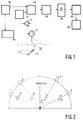
- Fig. 1 illustrates an ultrasound blood velocity measurement system which incorporates the invention.
- a transmitter 100 excites an ultrasound transducer 110 via a TR switch 120 to transmit broadband pulses of ultrasound energy into a body 130 along a narrow beam 140.
- the ultrasound energy in the beam is backscattered from structures in the body, for example from blood flowing in an artery 150, to produce echoes which return to and are detected by transducer 110.
- the frequency of the ultrasound signals scattered from structures in the body, which are moving in the direction of the axis of the beam 140 will be shifted with respect to the frequency of the ultrasound energy produced by the transducer in accordance with the Doppler equation. Echo signals produced by the transducer are coupled to a receiver 160 via the TR switch 120 and are amplified therein.
- the output of the receiver is connected to a radio frequency digitizer 170 which extracts and digitizes samples of the echo signals.
- the output of the digitizer is connected to the input of a range and line gate 180.
- Each transmitted PF pulse produces an A-line signal which maps range along the axis of beam 140 into signal arrival time.
- Control circuit 190 operates range gate 180 to select signal samples which originate within the region of the body defined by range, R, and beam 140.
- the digitizer 170 periodically samples the RF signal of the A-line at a rate which is at least twice the frequency of the highest component in the signal. Successive samples which lie within the range, R, along each A-line are stored as a column vector in a matrix array in memory 200.
- Successive A-lines are stored at successive column in the matrix so that each row of the matrix represents samples taken at corresponding ranges along successive A-lines.
- Individual elements stored in the matrix in memory 200 may thus be identified and addressed by a "fast-time” index, (which identifies a sample along each A-line and thus a row in the matrix) in conjunction with a "slow-time” index (which identifies the specific A-line and thus the column in the matrix).
- the array stored in memory 200 is processed in a two-dimensional discrete Fourier transform processor 210 and the results are stored in a second memory 220.
- the processor 210 may either be accomplished as a software routine in a general purpose digital computer or a microprocessor or, alternately, may be effected by dedicated fast Fourier transform processor chips.
- the output of the processor 210 is an array of data elements which represent the transform of the sampled A-line data with respect to a first (slow-time) variable which identifies individual A-line vectors in a data set and a second (fast-time) variable which represents the discrete sample position along each A-line.
- the array in memory 220 may be interpreted as a two-dimensional frequency spectrum representation with respect to a fast frequency variable which corresponds to the RF frequency spectrum of the received echo signal and a slow-frequency variable which corresponds to the Doppler frequency components.
- the spectral data stored in memory 220 are processed in an analyzer 230 to extract velocity information.
- the velocity spectrum is determined by radial projection in the two-dimensional Fourier frequency space.
- the angle, ⁇ , and hence the velocity, v, is estimated by computing the radial projection of the magnitude of the two-dimensional Fourier transform as taught by U.S. Patent 4,930,513.
- the two-dimensional Fourier transform data in memory 220 will include alias spectral components, A, as well as true spectral components, T (Fig. 2).
- the radial projections, a, of the alias spectra, A will have smaller magnitude and be wider than the radial projection, t, of the true spectrum, T.
- Fig. 3 which is a cartesian plot of a radial projection velocity spectrum.
- all of the alias components are not necessarily contiguous.
- one of the alias components, a* may wrap around the end of the spectrum.
- the analyzer 230 includes a program which divides the radial projection (Fig. 5) spectrum into window, W1 ---- W n , using the troughs between terms as the window edges. This is accomplished by an iterative calculation that successively approximates the location of the mean, M, of the spectrum such that the terms are evenly divided. Initially the mean is computed starting at the fist data sample in the spectrum. If the computed mean is at the center of the spectrum, then the starting point has been found. If the mean is not at the center, the spectrum is rotated so that the initially computed mean is at the center and the new mean of the rotated spectrum is calculated. The process is iterated until the mean of the rotated spectrum is at its center.
- each term can then be computed and tested to identify the true spectrum term, t, and the alias terms are suppressed.
- Appendix A contains an example of a C language computer program with a module alias_sup which implements the alias suppression techniques of the invention.
Landscapes
- Physics & Mathematics (AREA)
- Engineering & Computer Science (AREA)
- Radar, Positioning & Navigation (AREA)
- Remote Sensing (AREA)
- Acoustics & Sound (AREA)
- General Physics & Mathematics (AREA)
- Computer Networks & Wireless Communication (AREA)
- Multimedia (AREA)
- Aviation & Aerospace Engineering (AREA)
- Ultra Sonic Daignosis Equipment (AREA)
- Measurement Of Velocity Or Position Using Acoustic Or Ultrasonic Waves (AREA)
Applications Claiming Priority (2)
| Application Number | Priority Date | Filing Date | Title |
|---|---|---|---|
| US07/614,351 US5048528A (en) | 1990-11-15 | 1990-11-15 | Alias suppression in pulsed doppler systems |
| US614351 | 1990-11-15 |
Publications (2)
| Publication Number | Publication Date |
|---|---|
| EP0486096A1 true EP0486096A1 (de) | 1992-05-20 |
| EP0486096B1 EP0486096B1 (de) | 1999-05-06 |
Family
ID=24460877
Family Applications (1)
| Application Number | Title | Priority Date | Filing Date |
|---|---|---|---|
| EP91202895A Expired - Lifetime EP0486096B1 (de) | 1990-11-15 | 1991-11-07 | Unterdrückung des Überfaltungsartefaktes in Puls-Dopplersystemen |
Country Status (4)
| Country | Link |
|---|---|
| US (1) | US5048528A (de) |
| EP (1) | EP0486096B1 (de) |
| JP (1) | JP2991552B2 (de) |
| DE (1) | DE69131194T2 (de) |
Families Citing this family (5)
| Publication number | Priority date | Publication date | Assignee | Title |
|---|---|---|---|---|
| US5188114A (en) * | 1990-10-31 | 1993-02-23 | Hewlett-Packard Company | Method and apparatus for elimination of mirroring in signal processing system |
| US5349525A (en) * | 1993-01-08 | 1994-09-20 | General Electric Company | Color flow imaging system utilizing a frequency domain wall filter |
| US5386830A (en) * | 1993-10-25 | 1995-02-07 | Advanced Technology Laboratories, Inc. | Ultrasonic pulsed doppler flow measurement system with two dimensional autocorrelation processing |
| WO2017143456A1 (en) | 2016-02-26 | 2017-08-31 | The University Of Western Ontario | Doppler measurement system and method |
| US20230194705A1 (en) * | 2021-12-20 | 2023-06-22 | Aptiv Technologies Limited | Movement Compensation for Multi-Dimensional Radar Signal Processing |
Citations (2)
| Publication number | Priority date | Publication date | Assignee | Title |
|---|---|---|---|---|
| EP0161956A1 (de) * | 1984-04-06 | 1985-11-21 | Cgr Ultrasonic | Verfahren zur eindeutigen Dopplergeschwindigkeitsmessung eines bewegten Objektes |
| EP0358249A2 (de) * | 1988-07-26 | 1990-03-14 | Koninklijke Philips Electronics N.V. | Verfahren und Vorrichtung zur Fourier-Signalverarbeitung von gepulsten Doppler-Signalen |
Family Cites Families (4)
| Publication number | Priority date | Publication date | Assignee | Title |
|---|---|---|---|---|
| US4607642A (en) * | 1984-04-19 | 1986-08-26 | Advanced Technology Laboratories | Unaliased quadrature audio synthesizer |
| JPH0613031B2 (ja) * | 1987-08-12 | 1994-02-23 | 株式会社東芝 | 超音波血流イメ−ジング装置 |
| JPS6443238A (en) * | 1987-08-12 | 1989-02-15 | Toshiba Corp | Ultrasonic blood flow imaging apparatus |
| US4955386A (en) * | 1987-11-27 | 1990-09-11 | Hitachi, Ltd. | Pulse doppler flow speed meter |
-
1990
- 1990-11-15 US US07/614,351 patent/US5048528A/en not_active Expired - Fee Related
-
1991
- 1991-11-07 DE DE69131194T patent/DE69131194T2/de not_active Expired - Fee Related
- 1991-11-07 EP EP91202895A patent/EP0486096B1/de not_active Expired - Lifetime
- 1991-11-12 JP JP3295790A patent/JP2991552B2/ja not_active Expired - Lifetime
Patent Citations (2)
| Publication number | Priority date | Publication date | Assignee | Title |
|---|---|---|---|---|
| EP0161956A1 (de) * | 1984-04-06 | 1985-11-21 | Cgr Ultrasonic | Verfahren zur eindeutigen Dopplergeschwindigkeitsmessung eines bewegten Objektes |
| EP0358249A2 (de) * | 1988-07-26 | 1990-03-14 | Koninklijke Philips Electronics N.V. | Verfahren und Vorrichtung zur Fourier-Signalverarbeitung von gepulsten Doppler-Signalen |
Non-Patent Citations (1)
| Title |
|---|
| IEEE TRANSACTIONS ON BIO-MEDICAL ELECTRONICS. vol. 36, no. 2, February 1989, NEW YORK US pages 232 - 237; P. TORTOLI: 'A tracking FFT processor for pulsed Doppler analysis beyond the Nyquist limit' * |
Also Published As
| Publication number | Publication date |
|---|---|
| JPH04268481A (ja) | 1992-09-24 |
| DE69131194T2 (de) | 1999-11-11 |
| EP0486096B1 (de) | 1999-05-06 |
| JP2991552B2 (ja) | 1999-12-20 |
| US5048528A (en) | 1991-09-17 |
| DE69131194D1 (de) | 1999-06-10 |
Similar Documents
| Publication | Publication Date | Title |
|---|---|---|
| US4930513A (en) | Two dimensional processing of pulsed Doppler signals | |
| US6130641A (en) | Imaging methods and apparatus using model-based array signal processing | |
| US7929375B2 (en) | Method and apparatus for improved active sonar using singular value decomposition filtering | |
| US4182173A (en) | Duplex ultrasonic imaging system with repetitive excitation of common transducer in doppler modality | |
| Keeler et al. | Signal processing for atmospheric radars | |
| US6193665B1 (en) | Doppler angle unfolding in ultrasound color flow and Doppler | |
| US5280787A (en) | Ultrasonic method and apparaus for determination of vessel location and size | |
| US5097836A (en) | Untrasound diagnostic equipment for calculating and displaying integrated backscatter or scattering coefficients by using scattering power or scattering power spectrum of blood | |
| US3889533A (en) | Acoustic wind sensor | |
| EP0952462A2 (de) | Verfahren und Anordnung zur Verbesserung der Anzeige von Biopsiekanülen in Ultraschall-Bilddarstelllung | |
| US20040267127A1 (en) | Transmitter patterns for multi beam reception | |
| EP0909395A2 (de) | Verfahren und vorrichtung zur bestimmung von bewegungen und geschwindigkeiten sich bewegender objekte | |
| JPH0613028B2 (ja) | 生体類の循環系の血流速の多次元流れマップを生成する装置 | |
| US5349525A (en) | Color flow imaging system utilizing a frequency domain wall filter | |
| JP2001187054A (ja) | 超音波ビーム経路の数値的最適化方式 | |
| US5077699A (en) | Digital bottom mapping | |
| US6176143B1 (en) | Method and apparatus for estimation and display of spectral broadening error margin for doppler time-velocity waveforms | |
| US7212466B2 (en) | Producing amplitude values for controlling pixel illumination on a sonar display | |
| US7942821B2 (en) | Doppler velocity detection device and ultrasonographic device using the same | |
| US5373848A (en) | Ultrasonic time-domain method for sensing fluid flow | |
| EP0486096B1 (de) | Unterdrückung des Überfaltungsartefaktes in Puls-Dopplersystemen | |
| WO1995021572A1 (en) | Estimating target velocity from pulse echoes | |
| US5383462A (en) | Wideband time-domain cross-correlation method using baseband data | |
| US5696516A (en) | Radar system and accurate method of range resolution | |
| EP1774360B1 (de) | Hochauflösende bilder aus reflexionswellenenergie |
Legal Events
| Date | Code | Title | Description |
|---|---|---|---|
| PUAI | Public reference made under article 153(3) epc to a published international application that has entered the european phase |
Free format text: ORIGINAL CODE: 0009012 |
|
| AK | Designated contracting states |
Kind code of ref document: A1 Designated state(s): DE FR GB |
|
| 17P | Request for examination filed |
Effective date: 19921229 |
|
| 17Q | First examination report despatched |
Effective date: 19940809 |
|
| APAB | Appeal dossier modified |
Free format text: ORIGINAL CODE: EPIDOS NOAPE |
|
| APAA | Appeal reference recorded |
Free format text: ORIGINAL CODE: EPIDOS REFN |
|
| APAB | Appeal dossier modified |
Free format text: ORIGINAL CODE: EPIDOS NOAPE |
|
| GRAG | Despatch of communication of intention to grant |
Free format text: ORIGINAL CODE: EPIDOS AGRA |
|
| RAP3 | Party data changed (applicant data changed or rights of an application transferred) |
Owner name: KONINKLIJKE PHILIPS ELECTRONICS N.V. |
|
| GRAG | Despatch of communication of intention to grant |
Free format text: ORIGINAL CODE: EPIDOS AGRA |
|
| GRAH | Despatch of communication of intention to grant a patent |
Free format text: ORIGINAL CODE: EPIDOS IGRA |
|
| GRAH | Despatch of communication of intention to grant a patent |
Free format text: ORIGINAL CODE: EPIDOS IGRA |
|
| GRAA | (expected) grant |
Free format text: ORIGINAL CODE: 0009210 |
|
| AK | Designated contracting states |
Kind code of ref document: B1 Designated state(s): DE FR GB |
|
| REF | Corresponds to: |
Ref document number: 69131194 Country of ref document: DE Date of ref document: 19990610 |
|
| ET | Fr: translation filed | ||
| PLBE | No opposition filed within time limit |
Free format text: ORIGINAL CODE: 0009261 |
|
| STAA | Information on the status of an ep patent application or granted ep patent |
Free format text: STATUS: NO OPPOSITION FILED WITHIN TIME LIMIT |
|
| 26N | No opposition filed | ||
| PGFP | Annual fee paid to national office [announced via postgrant information from national office to epo] |
Ref country code: FR Payment date: 20001121 Year of fee payment: 10 |
|
| PGFP | Annual fee paid to national office [announced via postgrant information from national office to epo] |
Ref country code: GB Payment date: 20001129 Year of fee payment: 10 |
|
| PGFP | Annual fee paid to national office [announced via postgrant information from national office to epo] |
Ref country code: DE Payment date: 20010118 Year of fee payment: 10 |
|
| PG25 | Lapsed in a contracting state [announced via postgrant information from national office to epo] |
Ref country code: GB Free format text: LAPSE BECAUSE OF NON-PAYMENT OF DUE FEES Effective date: 20011107 |
|
| REG | Reference to a national code |
Ref country code: GB Ref legal event code: IF02 |
|
| GBPC | Gb: european patent ceased through non-payment of renewal fee |
Effective date: 20011107 |
|
| PG25 | Lapsed in a contracting state [announced via postgrant information from national office to epo] |
Ref country code: DE Free format text: LAPSE BECAUSE OF NON-PAYMENT OF DUE FEES Effective date: 20020702 |
|
| PG25 | Lapsed in a contracting state [announced via postgrant information from national office to epo] |
Ref country code: FR Free format text: LAPSE BECAUSE OF NON-PAYMENT OF DUE FEES Effective date: 20020730 |
|
| REG | Reference to a national code |
Ref country code: FR Ref legal event code: ST |
|
| REG | Reference to a national code |
Ref country code: FR Ref legal event code: ST |
|
| APAH | Appeal reference modified |
Free format text: ORIGINAL CODE: EPIDOSCREFNO |