EP0486179A2 - Appareil pour régler la diffusion d'un gaz - Google Patents
Appareil pour régler la diffusion d'un gaz Download PDFInfo
- Publication number
- EP0486179A2 EP0486179A2 EP91309963A EP91309963A EP0486179A2 EP 0486179 A2 EP0486179 A2 EP 0486179A2 EP 91309963 A EP91309963 A EP 91309963A EP 91309963 A EP91309963 A EP 91309963A EP 0486179 A2 EP0486179 A2 EP 0486179A2
- Authority
- EP
- European Patent Office
- Prior art keywords
- gas
- barrier
- gas inlet
- vapour
- diffusion
- Prior art date
- Legal status (The legal status is an assumption and is not a legal conclusion. Google has not performed a legal analysis and makes no representation as to the accuracy of the status listed.)
- Withdrawn
Links
Images

Classifications
-
- G—PHYSICS
- G01—MEASURING; TESTING
- G01N—INVESTIGATING OR ANALYSING MATERIALS BY DETERMINING THEIR CHEMICAL OR PHYSICAL PROPERTIES
- G01N27/00—Investigating or analysing materials by the use of electric, electrochemical, or magnetic means
- G01N27/26—Investigating or analysing materials by the use of electric, electrochemical, or magnetic means by investigating electrochemical variables; by using electrolysis or electrophoresis
- G01N27/403—Cells and electrode assemblies
- G01N27/404—Cells with anode, cathode and cell electrolyte on the same side of a permeable membrane which separates them from the sample fluid, e.g. Clark-type oxygen sensors
-
- G—PHYSICS
- G01—MEASURING; TESTING
- G01N—INVESTIGATING OR ANALYSING MATERIALS BY DETERMINING THEIR CHEMICAL OR PHYSICAL PROPERTIES
- G01N33/00—Investigating or analysing materials by specific methods not covered by groups G01N1/00 - G01N31/00
- G01N33/0004—Gaseous mixtures, e.g. polluted air
- G01N33/0009—General constructional details of gas analysers, e.g. portable test equipment
- G01N33/0011—Sample conditioning
Definitions
- This invention relates to a gas diffusion control assembly, for example for use with a gas sensor, and a method of making such an assembly.
- An example of a gas sensor is an electro- chemical sensor for the measurement of concentrations of gas or vapour in accordance with the limiting current principle comprising an electrolytic cell having a sensing electrode, a counter electrode and an intervening body of electrolyte, the sensor also including a restriction to the rate of access of gas or vapour to the sensing electrode.
- Electro- chemical sensors of this type are described in GB-A-1571282 and GB-A-2049952.
- Commercial oxygen sensors which have been built incorporate a capillary to constitute the barrier. Although these sensors have proved to be very successful, they are relatively expensive to build and, particularly in the case of oxygen sensors, have a relatively short service period.
- a gas diffusion control assembly comprises a gas inlet; a restriction to the rate of flow of gas or vapour from the gas inlet in the form of a porous diffusion barrier extending across the gas inlet; and control means for causing all gas or vapour passing out of the inlet into the diffusion barrier to diffuse through part of the barrier along a path with a lateral outward component relative to the direction of access through the gas inlet.
- the porous barrier may comprise a gas phase diffusion barrier in which gas remains in the gas phase during its passage through the barrier, a Knudsen barrier in which the active pores are sufficiently small as to cause diffusion through them to be in accordance with the Knudsen principle (ie. diffusion rate governed by pore wall collisions, rather than inter-molecular collisions), or a mixture of the two types of barrier.
- the control means for causing lateral gas diffusion may comprise an impermeable member such as a polythene disk bonded to the barrier.
- the assembly is formed substantially symmetrically, the gas inlet defining a gas diffusion path centred on the axis of symmetry.
- the means for causing lateral gas diffusion is arranged preferably to cause gas to diffuse laterally outward substantially symmetrically about the axis of symmetry.
- the sensing electrode is preferably positioned parallel with respect to the porous diffusion barrier such that gas can enter the microporous backing tape of the electrode beyond the periphery of the area defined by the control means (such as an impermeable polythene disc), and thence into an electrocatalyst layer of the sensor without any further significant diffusion resistance.
- the control means such as an impermeable polythene disc
- Orientation effects in conventional sensors can be caused by the flexure of the sensing electrode which leads to bulk flow of gas and resultant current transients on the sensor signal.
- the magnitude of these transients is related to the internal gas volume downstream of the diffusion barrier.
- the above barrier design reduces any bulk flow effects, including orientation effects, by presenting a low permeability gas access pathway.
- a gas sensor comprises a sensing electrode catalyst layer; a counter electrode; and a gas diffusion control assembly according to the first aspect of the invention, in which the porous diffusion barrier is fixed directly to the sensing electrode catalyst layer.
- This fixing may be by direct pressure bonding, heat sealing, or any other means between the barrier and electrode.
- the porous barrier and control means eg. an impermeable disc composite, act as both the main diffusion barrier and the electrode supporting tape, thereby reducing the internal gas volume to a very low level and virtually eliminating orientation effects due to electrode flexure.
- a gas diffusion control assembly comprises a gas inlet; a restriction to the rate of access of gas or vapour to the gas inlet in the form of a gas phase diffusion barrier extending across the gas inlet; and control means for causing all gas or vapour to pass to the gas inlet through part of the barrier along a path with a lateral component relative to the direction of access through the gas inlet.
- control means for causing lateral gas diffusion may comprise an impermeable member such as a polythene disc bonded to the barrier.
- the assembly according to the third aspect of the present invention is particularly useful since by providing the barrier upstream of the gas inlet, it is possible to control accurately the diffusibility of the barrier and, in the case of a gas sensor to which the assembly is connected, tune the sensor signal.
- a method of manufacturing a gas diffusion control assembly comprises providing a gas inlet through which gas or vapour can travel; positioning a porous diffusion barrier across the gas inlet to restrict the rate of access of gas or vapour to the gas inlet; positioning a thermoplastic member in contact with the porous diffusion barrier; and heating the thermoplastic member and the porous diffusion barrier so as to cause the thermoplastic material to impregnate the barrier and/or to cause the pores of the barrier to be compressed until a desired diffusibility is achieved.
- the fourth aspect of the invention recognises that by exposing the porous diffusion barrier, it is possible to control the diffusion characteristic of the barrier by a suitable heat treatment.
- porous diffusion barrier used in methods according to the fourth aspect of the invention may comprise a gas phase diffusion barrier, a Knudsen diffusion barrier or a mixture of the two types of barrier.
- the gas diffusion control assembly is connected to a gas sensing device to form a gas sensor, the assembly controlling the rate of access of gas or vapour to the sensing device.
- the gas sensing device may comprise an electrochemical sensor for the measurement of concentrations of gas or vapour in accordance with the limiting current principle, the sensing device comprising an electrolytic cell having a sensing electrode, a counter electrode and an intervening body of electrolyte.
- the gas sensor is much simpler and cheaper to construct and generates currents which are reduced compared to equivalent capillary based sensors.
- a conventional capillary sensor will generate a current in the order of one mA in air (21 % oxygen) whereas a sensor according to the invention can easily be constructed which generates much smaller currents in the order of 0.1 mA or less in ambient air.
- the problems of bulk flow are considerably reduced and the capillary is dispensed with. This leads to a much cheaper and compact construction.
- a gas sensor comprises:
- the first sub-assembly comprises a gas diffusion control assembly according to the first or third aspect of the invention or manufactured in accordance with the fourth aspect of the invention.
- the porous diffusion barrier will have a generally disc like form but in some cases it may be in the form of a strip or sector such as a semi-circle or quadrant.
- the sensor of which part is shown in Figure 1 includes a circular top plate 1 (of diameter about 30 mm) provided with a gas access hole 2 having a length of about 3 mm and a diameter of about 2 mm. Heat sealed to the plate 1 is a porous PTFE disk 3 of diameter about 10 mm and thickness about 0.18 mm which defines a diffusion barrier.
- the diffusion barrier may be a pure gas phase diffusion barrier, a barrier operating on the Knudsen principle, or a barrier with a combination of these properties. Gas enters the sensor through the access hole 2 and passes into the diffusion barrier 3.
- the gas is prevented from passing directly, in a straight line, through the barrier 3 by a polythene disk 4 (diameter 7 mm and thickness 0.1 mm) heat sealed to the underside of the barrier 3.
- a porous PTFE backing tape 5 (19 mm diameter and 0.18 mm thickness) is heat sealed to the disk 4 while a sensing electrode catalyst layer 6 (19 mm diameter and 0.18 mm thickness) is mounted to the tape 5.
- Electrolyte contacts the catalyst layer 6 in the region 7.
- An annular portion of the surface of the backing tape 5 is heat sealed at 8 to the top plate 1 (shown spaced apart in Figure 1) to prevent electrolyte reaching the barrier 3.
- the sensor would also include a metallic counter electrode, an intervening body of electrolyte absorbed in separators between the electrodes, and suitable containment hardware which are not shown in this drawing.
- the sensor is connected in a conventional electric circuit of the type shown in Figure 6.
- the sensing electrode 6 (indicated by S) and the counter electrode C are connected across a load resistor R L .
- Electrochemical reactions at the electrodes generate an electric current which flows between the electrodes through the circuit containing R L .
- the current generated by this sensor design is directly proportional to the oxygen concentration in the atmosphere to which the sensor is exposed and therefore the value of the voltage across terminals 41 provides a direct measure of oxygen concentration. This voltage can either be directly measured or amplified as required.
- Figure 6 is a very simplified view but it represents a typical, conventional circuit for use with gas sensors of this type.
- An additional "diffuser" membrane (not shown in Figure 1) of low diffusion resistance may optionally be placed between the PTFE backing tape 5 and the composite polythene disk 4 porous PTFE disk 3 to facilitate the spreading of the gas diffusion flux across the electrocatalyst section 6.
- the disc 3 is described as the barrier, but the tape 5 could also act as a restriction although it should preferably have minimal effect in this connection providing it acts as a barrier against electrolyte flow.
- Figure 2 illustrates part of a sensor similar to that shown in Figure 1 but in this case the porous PTFE disk 3 (19 mm diameter and 0.18 mm thickness) also acts as a backing tape in place of the tape 5 in the Figure 1 example while the polythene disk 4 is embedded within the electrode catalyst layer 6.
- the porous PTFE disk 3 (19 mm diameter and 0.18 mm thickness) also acts as a backing tape in place of the tape 5 in the Figure 1 example while the polythene disk 4 is embedded within the electrode catalyst layer 6.
- the Figure 2 example is preferred since the number of heat sealing steps is reduced. Indeed, a single heat sealing tool can be applied just once to achieve the heat seal between the PTFE disc 3 and the plate 1 and between the polythene disc 4 and the disc 3. This latter arrangement is the most preferred since not only is a single heat sealing step necessary but it virtually eliminates free internal gas space and there will be no orientation effects due to relative movement between the component parts.
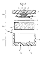
- Figure 3 illustrates a complete sensor in an exploded view which is not to scale based on the Figure 1 example.
- the plate 1 is provided with an O-ring groove 30 to enable the sensor to be sealed to an enclosing housing while the gas access hole 2 communicates with a counterbore 31 in which is inserted a porous VYON plug 10 which acts to exclude water droplets.
- a second sub-assembly SA2 comprises a pre-formed porous Pb wool anode 11 (counter electrode) with an expanded stainless steel mesh disk current collector 12 secured within a thin, insulating plastics clip 13.
- the sub-assemblies SA1 and SA2 are connected together with a separator 14 between them.
- a third sub-assembly SA3 comprises an ABS can 18 having a cup-shaped form.
- a pair of Ni PCB pins 15,16 extend through the base of the base plate 14 so as to contact the sensing electrode catalyst layer 6 and the anode 11 respectively. Connection between the pin 15 and the sensing electrode catalyst layer 6 is achieved via a Ni foil current collector 17.
- the sensor is assembled by placing sub-assembly SA2 into sub-assembly SA3.
- the can 18 is then filled with electrolyte.
- Sub-assembly SA1 is then placed in the can 18 with separator 14 between sub-assemblies SA2 and SA1. The separator will wet up with the electrolyte.
- the invention has been described in connection with two electrode sensors, it is also possible for use with three electrode sensors in which a reference electrode is also provided.
- the sensor is particularly suitable for use with oxygen, it could be used with any other gas which reacts electrochemically at the sensing electrode. With gases which react anodically at the sensing electrode, such as carbon monoxide, hydrogen sulphide, etc, the metallic counter electrode needs to be replaced with a suitable electrode able to undergo an electrochemical reduction (cathodic) reaction.
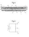
- Figure 4 illustrates a further example of a gas sensor.
- a polythene disc 20 (12 mm diameter and 0.10 mm thickness) is sandwiched between two porous PTFE discs 21, 22 (19 mm diameter and 0.18 mm thickness) with the contacting surfaces being (heat) sealed between polythene and PTFE as shown dotted in the diagram.
- the sandwich of disc 20 and discs 21, 22 is sealed into the sensor body 24, the sealed areas being shown dotted.
- Gas passing through the orifice 23 passes through a diffuser 25 (12 mm diameter and 0.18 mm thickness) which is optional, a porous PTFE backing tape 26 (19 mm diameter and 0.8 mm thickness) and into an electro-catalyst layer 27 (12 mm diameter and 0.18 mm thickness) where it undergoes an electro-chemical reaction.
- the unit shown in Figure 4 can be formed as a sub-assembly and the different components can be heat sealed together as shown in a single heat sealing step by application of a heat seal shoe against the upper PTFE disc 21.
- the application of this shoe can be done in a controlled manner so as to cause the polythene disc 20 partially to impregnate the pores of the discs 21, 22 so as to affect the diffusion resistance of the discs.
- the heat sealing can be arranged to cause the pores of the discs 21, 22 to be partially closed thus increasing the diffusion resistance.
- the sub-assembly shown in Figure 4 can be incorporated into a full gas sensor of the type shown in Figure 3 in place of the sub-assembly in SA1 shown in that diagram.
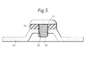
- Figure 5 illustrates a further example in which a screw 50 having a wide flange 51 is screw-threaded into a bore 52 in a metal cap 53.
- a PTFE washer 54 is sandwiched between the flange 51 and the cap 53.
- gas diffuses laterally inwards towards the shank of the screw 50 through the PTFE washer 54 and then percolates through the bore 52 via the screw-threads.
- the diffusibility can be relatively easily controlled simply by turning the screw 50 and adjusting the compression of the washer 54.
Landscapes
- Chemical & Material Sciences (AREA)
- Life Sciences & Earth Sciences (AREA)
- Health & Medical Sciences (AREA)
- Pathology (AREA)
- General Physics & Mathematics (AREA)
- Engineering & Computer Science (AREA)
- Physics & Mathematics (AREA)
- Analytical Chemistry (AREA)
- Biochemistry (AREA)
- General Health & Medical Sciences (AREA)
- Immunology (AREA)
- Chemical Kinetics & Catalysis (AREA)
- Molecular Biology (AREA)
- Electrochemistry (AREA)
- Combustion & Propulsion (AREA)
- Food Science & Technology (AREA)
- Medicinal Chemistry (AREA)
- Measuring Oxygen Concentration In Cells (AREA)
- Investigating Or Analyzing Materials By The Use Of Fluid Adsorption Or Reactions (AREA)
Applications Claiming Priority (4)
| Application Number | Priority Date | Filing Date | Title |
|---|---|---|---|
| GB909024521A GB9024521D0 (en) | 1990-11-12 | 1990-11-12 | Gas sensor |
| GB9024521 | 1990-11-12 | ||
| GB919106531A GB9106531D0 (en) | 1991-03-27 | 1991-03-27 | Gas diffusion control assembly |
| GB9106531 | 1991-03-27 |
Publications (2)
| Publication Number | Publication Date |
|---|---|
| EP0486179A2 true EP0486179A2 (fr) | 1992-05-20 |
| EP0486179A3 EP0486179A3 (en) | 1992-07-08 |
Family
ID=26297936
Family Applications (1)
| Application Number | Title | Priority Date | Filing Date |
|---|---|---|---|
| EP19910309963 Withdrawn EP0486179A3 (en) | 1990-11-12 | 1991-10-29 | Gas diffusion control assembly |
Country Status (4)
| Country | Link |
|---|---|
| US (1) | US5321971A (fr) |
| EP (1) | EP0486179A3 (fr) |
| JP (1) | JPH04291145A (fr) |
| CA (1) | CA2055008A1 (fr) |
Cited By (2)
| Publication number | Priority date | Publication date | Assignee | Title |
|---|---|---|---|---|
| EP0732587A1 (fr) * | 1995-03-16 | 1996-09-18 | SEM Corporation | Assemblage d'un capteur de gaz électrochimique |
| EP0780686A1 (fr) * | 1995-12-20 | 1997-06-25 | City Technology Limited | Capteur de gaz électrochimique |
Families Citing this family (8)
| Publication number | Priority date | Publication date | Assignee | Title |
|---|---|---|---|---|
| WO1998015818A1 (fr) * | 1996-10-10 | 1998-04-16 | Samsung Electronics Co., Ltd. | Circuit integre hybride pour capteur de gaz |
| JP3553316B2 (ja) * | 1997-05-20 | 2004-08-11 | 日本碍子株式会社 | ガスセンサ |
| US6071476A (en) * | 1997-11-14 | 2000-06-06 | Motorola, Inc. | Exhaust gas sensor |
| US6413395B1 (en) | 1999-12-16 | 2002-07-02 | Roche Diagnostics Corporation | Biosensor apparatus |
| FI20002057L (fi) * | 2000-09-18 | 2002-04-18 | Vaisala Oyj | Mittalaite kaasumaisen aineen diffuusion mittaamiseksi rakenteen pinnalta |
| DE10345141A1 (de) * | 2003-09-29 | 2005-04-21 | Bosch Gmbh Robert | Sensorelement |
| GB0700556D0 (en) * | 2007-01-11 | 2007-02-21 | Honeywell Int Inc | Electrochemical gas sensor |
| WO2022113389A1 (fr) * | 2020-11-25 | 2022-06-02 | マクセル株式会社 | Capteur d'oxygene electrochimique et procédé pour le produire |
Family Cites Families (21)
| Publication number | Priority date | Publication date | Assignee | Title |
|---|---|---|---|---|
| US3361162A (en) * | 1966-02-17 | 1968-01-02 | Allis Chalmers Mfg Co | Fluid flow controller |
| US3840209A (en) * | 1970-07-29 | 1974-10-08 | Anglo Amer Corp South Africa | Flow controlling devices |
| US3924219A (en) * | 1971-12-22 | 1975-12-02 | Minnesota Mining & Mfg | Gas detection device |
| JPS5268494A (en) * | 1975-12-03 | 1977-06-07 | Nippon Denso Co Ltd | Oxygen concentration detector |
| GB1571282A (en) * | 1976-03-11 | 1980-07-09 | City Tech | Gas sensor |
| GB2049952B (en) * | 1979-05-17 | 1983-03-30 | City Tech | Diffusion barrier gas sensor |
| US4326200A (en) * | 1979-05-18 | 1982-04-20 | Neotronics Limited | Gas detecting and measuring apparatus |
| JPS56117162A (en) * | 1980-02-21 | 1981-09-14 | Nissan Motor Co Ltd | Supporting structure for gas sensitive element |
| US4474648A (en) * | 1980-04-30 | 1984-10-02 | City Technology Limited | Gas sensor |
| GB2094005B (en) * | 1981-02-03 | 1985-05-30 | Coal Industry Patents Ltd | Electrochemical gas sensor |
| EP0095277A3 (fr) * | 1982-05-26 | 1984-07-04 | City Technology Limited | Capteur de gaz |
| US4446000A (en) * | 1983-05-13 | 1984-05-01 | Lynn Products Company, Incorporated | Oxygen sensor and method for making same |
| GB8313846D0 (en) * | 1983-05-19 | 1983-06-22 | City Tech | Gas sensor |
| GB8501040D0 (en) * | 1985-01-16 | 1985-02-20 | Neotronics Ltd | Gas sensor |
| GB8501039D0 (en) * | 1985-01-16 | 1985-02-20 | Neotronics Ltd | Gas sensor |
| GB8508001D0 (en) * | 1985-03-27 | 1985-05-01 | Neotronics Ltd | Gas sensor |
| US4824551A (en) * | 1985-06-11 | 1989-04-25 | Gas Research Institute | Cell for measuring gas levels |
| US4790925A (en) * | 1987-09-18 | 1988-12-13 | Mine Safety Appliances Company | Electrochemical gas sensor |
| US5082239A (en) * | 1988-06-20 | 1992-01-21 | Laminar Fluid Controls, Inc. | Radial flow valve assembly |
| JPH0381658A (ja) * | 1989-08-24 | 1991-04-08 | Matsushita Electric Ind Co Ltd | ガス濃度検知素子 |
| US4986502A (en) * | 1989-12-04 | 1991-01-22 | Ceroke Clarence J | Safety drain plug |
-
1991
- 1991-10-29 EP EP19910309963 patent/EP0486179A3/en not_active Withdrawn
- 1991-11-06 CA CA002055008A patent/CA2055008A1/fr not_active Abandoned
- 1991-11-12 JP JP3322373A patent/JPH04291145A/ja not_active Withdrawn
-
1992
- 1992-11-10 US US07/974,383 patent/US5321971A/en not_active Expired - Fee Related
Cited By (3)
| Publication number | Priority date | Publication date | Assignee | Title |
|---|---|---|---|---|
| EP0732587A1 (fr) * | 1995-03-16 | 1996-09-18 | SEM Corporation | Assemblage d'un capteur de gaz électrochimique |
| EP0780686A1 (fr) * | 1995-12-20 | 1997-06-25 | City Technology Limited | Capteur de gaz électrochimique |
| US5746899A (en) * | 1995-12-20 | 1998-05-05 | City Technology Limited | Electrochemical gas sensor |
Also Published As
| Publication number | Publication date |
|---|---|
| EP0486179A3 (en) | 1992-07-08 |
| JPH04291145A (ja) | 1992-10-15 |
| CA2055008A1 (fr) | 1992-05-13 |
| US5321971A (en) | 1994-06-21 |
Similar Documents
| Publication | Publication Date | Title |
|---|---|---|
| US4132616A (en) | Gas sensor | |
| CA2360616C (fr) | Detecteur a ionomere de polymere solide de type film et cellule de detection | |
| US4820386A (en) | Diffusion-type sensor cell containing sensing and counter electrodes in intimate contact with the same side of a proton-conducting membrane and method of use | |
| JP3706137B2 (ja) | ガスセンサー | |
| JPH0656376B2 (ja) | 電気化学的ガス・センサ | |
| US6558519B1 (en) | Gas sensors | |
| CA2309646C (fr) | Detecteur de gaz | |
| US4324632A (en) | Gas sensor | |
| CA2326210C (fr) | Capteur d'hydrogene | |
| US5668302A (en) | Electrochemical gas sensor assembly | |
| US4017373A (en) | Electrochemical sensing cell | |
| US10914705B2 (en) | Electrochemical sensor | |
| EP1959253A2 (fr) | Capteur électrochimique | |
| US6099708A (en) | Three-electrode electrochemical gas sensor | |
| US6666963B1 (en) | Oxygen sensor | |
| US6668616B1 (en) | Carbon monoxide sensor | |
| US5321971A (en) | Gas diffusion control assembly | |
| US4051006A (en) | Portable electrochemical cell structure | |
| US20020125131A1 (en) | Micro-fuel cell sensor apparatus and method for modeling the sensor response time | |
| US6436257B1 (en) | Means for detecting and measuring the concentration of acetylene dissolved in a fluid | |
| GB2049952A (en) | Diffusion barrier gas sensor | |
| JPS62269055A (ja) | 電気化学センサ− | |
| KR100823319B1 (ko) | 하이브리드 산소 가스 센서 | |
| JP2003207483A (ja) | ガスセンサ | |
| JP2003021616A (ja) | 水素ガス濃度検出器 |
Legal Events
| Date | Code | Title | Description |
|---|---|---|---|
| PUAI | Public reference made under article 153(3) epc to a published international application that has entered the european phase |
Free format text: ORIGINAL CODE: 0009012 |
|
| PUAL | Search report despatched |
Free format text: ORIGINAL CODE: 0009013 |
|
| AK | Designated contracting states |
Kind code of ref document: A2 Designated state(s): DE FR GB IT |
|
| AK | Designated contracting states |
Kind code of ref document: A3 Designated state(s): DE FR GB IT |
|
| 17P | Request for examination filed |
Effective date: 19920918 |
|
| RAP1 | Party data changed (applicant data changed or rights of an application transferred) |
Owner name: THE GOVERNOR AND COMPANY OF THE BANK OF SCOTLAND |
|
| 111Z | Information provided on other rights and legal means of execution |
Free format text: DE FR GB IT |
|
| 17Q | First examination report despatched |
Effective date: 19940825 |
|
| STAA | Information on the status of an ep patent application or granted ep patent |
Free format text: STATUS: THE APPLICATION IS DEEMED TO BE WITHDRAWN |
|
| 18D | Application deemed to be withdrawn |
Effective date: 19950105 |