EP0486255B1 - Metalldichtung - Google Patents
Metalldichtung Download PDFInfo
- Publication number
- EP0486255B1 EP0486255B1 EP19910310422 EP91310422A EP0486255B1 EP 0486255 B1 EP0486255 B1 EP 0486255B1 EP 19910310422 EP19910310422 EP 19910310422 EP 91310422 A EP91310422 A EP 91310422A EP 0486255 B1 EP0486255 B1 EP 0486255B1
- Authority
- EP
- European Patent Office
- Prior art keywords
- beads
- metallic
- portions
- cylinder bore
- parts
- Prior art date
- Legal status (The legal status is an assumption and is not a legal conclusion. Google has not performed a legal analysis and makes no representation as to the accuracy of the status listed.)
- Expired - Lifetime
Links
- 239000011324 bead Substances 0.000 claims description 138
- 230000001105 regulatory effect Effects 0.000 claims description 37
- 239000000463 material Substances 0.000 claims description 18
- 230000006835 compression Effects 0.000 claims description 10
- 238000007906 compression Methods 0.000 claims description 10
- 239000007769 metal material Substances 0.000 claims description 9
- 238000005452 bending Methods 0.000 claims description 4
- 229920001971 elastomer Polymers 0.000 claims description 4
- 229920005989 resin Polymers 0.000 claims description 4
- 239000011347 resin Substances 0.000 claims description 4
- OKTJSMMVPCPJKN-UHFFFAOYSA-N Carbon Chemical compound [C] OKTJSMMVPCPJKN-UHFFFAOYSA-N 0.000 claims 1
- 239000004760 aramid Substances 0.000 claims 1
- 229920003235 aromatic polyamide Polymers 0.000 claims 1
- 229910002804 graphite Inorganic materials 0.000 claims 1
- 239000010439 graphite Substances 0.000 claims 1
- 238000007789 sealing Methods 0.000 description 20
- 230000035882 stress Effects 0.000 description 12
- 230000007423 decrease Effects 0.000 description 10
- 239000000567 combustion gas Substances 0.000 description 7
- 238000002485 combustion reaction Methods 0.000 description 6
- 229910052751 metal Inorganic materials 0.000 description 6
- 239000002184 metal Substances 0.000 description 6
- 238000010276 construction Methods 0.000 description 4
- 230000000694 effects Effects 0.000 description 4
- 230000001788 irregular Effects 0.000 description 4
- 238000004519 manufacturing process Methods 0.000 description 4
- 230000002093 peripheral effect Effects 0.000 description 4
- XLYOFNOQVPJJNP-UHFFFAOYSA-N water Substances O XLYOFNOQVPJJNP-UHFFFAOYSA-N 0.000 description 4
- 229910000838 Al alloy Inorganic materials 0.000 description 3
- 230000007797 corrosion Effects 0.000 description 3
- 238000005260 corrosion Methods 0.000 description 3
- 239000012530 fluid Substances 0.000 description 3
- 125000006850 spacer group Chemical group 0.000 description 3
- 229910001069 Ti alloy Inorganic materials 0.000 description 2
- 230000015572 biosynthetic process Effects 0.000 description 2
- 238000004880 explosion Methods 0.000 description 2
- 230000005484 gravity Effects 0.000 description 2
- 238000000034 method Methods 0.000 description 2
- 238000001556 precipitation Methods 0.000 description 2
- 239000006104 solid solution Substances 0.000 description 2
- 229910052782 aluminium Inorganic materials 0.000 description 1
- XAGFODPZIPBFFR-UHFFFAOYSA-N aluminium Chemical compound [Al] XAGFODPZIPBFFR-UHFFFAOYSA-N 0.000 description 1
- 239000007767 bonding agent Substances 0.000 description 1
- 239000000498 cooling water Substances 0.000 description 1
- 230000003247 decreasing effect Effects 0.000 description 1
- 238000006073 displacement reaction Methods 0.000 description 1
- 230000008030 elimination Effects 0.000 description 1
- 238000003379 elimination reaction Methods 0.000 description 1
- 229920001973 fluoroelastomer Polymers 0.000 description 1
- 238000010438 heat treatment Methods 0.000 description 1
- 230000013011 mating Effects 0.000 description 1
- 239000012858 resilient material Substances 0.000 description 1
- 239000007779 soft material Substances 0.000 description 1
- 230000002195 synergetic effect Effects 0.000 description 1
- 230000008646 thermal stress Effects 0.000 description 1
Images




Classifications
-
- F—MECHANICAL ENGINEERING; LIGHTING; HEATING; WEAPONS; BLASTING
- F16—ENGINEERING ELEMENTS AND UNITS; GENERAL MEASURES FOR PRODUCING AND MAINTAINING EFFECTIVE FUNCTIONING OF MACHINES OR INSTALLATIONS; THERMAL INSULATION IN GENERAL
- F16J—PISTONS; CYLINDERS; SEALINGS
- F16J15/00—Sealings
- F16J15/02—Sealings between relatively-stationary surfaces
- F16J15/06—Sealings between relatively-stationary surfaces with solid packing compressed between sealing surfaces
- F16J15/08—Sealings between relatively-stationary surfaces with solid packing compressed between sealing surfaces with exclusively metal packing
- F16J15/0818—Flat gaskets
- F16J15/0825—Flat gaskets laminated
-
- F—MECHANICAL ENGINEERING; LIGHTING; HEATING; WEAPONS; BLASTING
- F16—ENGINEERING ELEMENTS AND UNITS; GENERAL MEASURES FOR PRODUCING AND MAINTAINING EFFECTIVE FUNCTIONING OF MACHINES OR INSTALLATIONS; THERMAL INSULATION IN GENERAL
- F16J—PISTONS; CYLINDERS; SEALINGS
- F16J15/00—Sealings
- F16J15/02—Sealings between relatively-stationary surfaces
- F16J15/06—Sealings between relatively-stationary surfaces with solid packing compressed between sealing surfaces
- F16J15/08—Sealings between relatively-stationary surfaces with solid packing compressed between sealing surfaces with exclusively metal packing
- F16J15/0818—Flat gaskets
- F16J2015/0837—Flat gaskets with an edge portion folded over a second plate or shim
-
- F—MECHANICAL ENGINEERING; LIGHTING; HEATING; WEAPONS; BLASTING
- F16—ENGINEERING ELEMENTS AND UNITS; GENERAL MEASURES FOR PRODUCING AND MAINTAINING EFFECTIVE FUNCTIONING OF MACHINES OR INSTALLATIONS; THERMAL INSULATION IN GENERAL
- F16J—PISTONS; CYLINDERS; SEALINGS
- F16J15/00—Sealings
- F16J15/02—Sealings between relatively-stationary surfaces
- F16J15/06—Sealings between relatively-stationary surfaces with solid packing compressed between sealing surfaces
- F16J15/08—Sealings between relatively-stationary surfaces with solid packing compressed between sealing surfaces with exclusively metal packing
- F16J15/0818—Flat gaskets
- F16J2015/0843—Flat gaskets with an edge portion folded over the plate itself
-
- F—MECHANICAL ENGINEERING; LIGHTING; HEATING; WEAPONS; BLASTING
- F16—ENGINEERING ELEMENTS AND UNITS; GENERAL MEASURES FOR PRODUCING AND MAINTAINING EFFECTIVE FUNCTIONING OF MACHINES OR INSTALLATIONS; THERMAL INSULATION IN GENERAL
- F16J—PISTONS; CYLINDERS; SEALINGS
- F16J15/00—Sealings
- F16J15/02—Sealings between relatively-stationary surfaces
- F16J15/06—Sealings between relatively-stationary surfaces with solid packing compressed between sealing surfaces
- F16J15/08—Sealings between relatively-stationary surfaces with solid packing compressed between sealing surfaces with exclusively metal packing
- F16J15/0818—Flat gaskets
- F16J2015/085—Flat gaskets without fold over
Definitions
- This invention relates to a metallic gasket for use in sealing a clearance between the opposed surfaces to be joined together of a cylinder head and a cylinder block.
- a gasket formed out of a metal has been used to seal a clearance between opposed surfaces to be joined together of structural members of an engine, such as a cylinder head and a cylinder block.
- Metallic gaskets which are developed for the purpose of improving their performance of sealing the high-pressure portions to be sealed, i.e. the peripheral portions of through bores, and which include a metallic gasket provided with a layer of a soft metal on the top portions of the beads (refer to, for example, Japanese Utility Model Laid-open No. 145665/1985), and a metallic gasket provided with a spacer (refer to, for example, Japanese Utility Model Laid-open No. 16459/1986), have been proposed.
- top portions are formed on the beads provided on the peripheral portions of through bores so as to increase the height of the beads.
- a metallic gasket is tightened between a cylinder head and a cylinder block to bring the opposed surfaces to be combined together of the structural members into pressure contact with each other, the metallic gasket is compressed more tightly by as much as the increase, which is ascribed to the provision of the layer of a soft metal or a spacer, of the height of the beads. Therefore, the improvement in the performance of the metallic gasket of sealing the surfaces combined of the portions of the structural members which are around the cylinder bore holes is expected. If the padding is done on such a metallic gasket by using a soft material, a local pressure imparted to the metallic gasket will be scattered, and the improvement of the sealing performance of the metallic gasket or the protection of the beads will be attained.
- a metallic gasket other than these prior art metallic gaskets is also known, in which grommets are attached to the circumferential portions, which are provided with beads projecting therefrom and constitute pressure-contacting portions to be sealed, of cylinder bore holes (refer to, for example, Japanese Patent Laid-open Nos. 101574/1988 and 149479/1988). Even when the grommets attached to the circumferential portions of the cylinder bore holes in this metallic gasket are exposed to a fluid of high temperature and pressure, such as a combustion gas, the sealing performance of the gasket is not deteriorated. Even if the leakage should occur in the grommets, the beads prevent the fluid from flowing out.
- this metallic gasket has a function of correcting the imperfect alignment of the opposed surfaces to be combined in addition to the fluid sealing function of the beads
- the operation for attaching grommets to the circumferential portions of the cylinder bore holes involves troublesome work, such as the manufacturing of grommets, the fitting of the grommets around the circumferences of the cylinder bore holes and the deformation-controlling of the grommets, and causes the manufacturing cost to increase.
- Japanese Patent Laid-open No. 101573/1988 discloses a metallic gasket shown in Figs. 18 and 19.
- This metallic gasket 18 is adapted to seal the clearance between the opposed surfaces to be combined of a cylinder head 23 and a cylinder block 24, and provided with a bead 21 projecting from the portion which constitutes a pressure-contacting surface to be sealed, and which is around a cylinder bore hole 19, and a seal member 22 in a valley portion 20 formed in the bead 21.
- a clearance is formed in the part of the valley portion 20 in the bead 21 which is around the seal member 22, so that the seal member 22 can be deformed elastically at large when the opposed surfaces to be combined are tightened.
- the number of sealing contact portions with respect to the opposed surfaces to be combined on both sides of the metallic gasket 18 does not increase in the positions which are spaced differently away from the cylinder bore holes 19 in the radial direction thereof.
- the seal members 22 can be provided unitarily with the metallic gasket 18 but that unitarily combining the seal members 22 with the metallic gasket 18 by using a bonding agent or heat will probably take much time since the valley portion 20 in the bead 21 in a free state in a stage in which the gasket has not yet been tightened has a considerably wide clearance.
- US-3053544 discloses a gasket according to preamble of claim 1 for use between mating or sealing flanges of a pressurized system, which gasket comprises a substantially flat sheet-like body of resilient material, an aperture in said body defined by a reversely curled lip thereof having its edge portion overlying and spaced from said body, a first bead on said body surrounding said lip and extending outwardly from said body to a lesser degree than said edge portion of said lip, and a second bead on said body surrounding said first bead and extending outwardly from said body in an opposite direction from said first bead, the distance from the top of said one bead being greater than twice the thickness of said material of said sheet-like body.
- a primary aim of the present invention is to solve these problems, and provide a simply constructed metallic gasket capable of correcting the imperfect alignment of the opposed surfaces to be combined, when a cylinder block and a cylinder head in an engine are tightened and fixed to each other via a single plate type elastic metallic body having beads and folded portions; practically offsetting strain, even if it should occur between adjacent cylinder bore holes due to the bend of the cylinder head, by the elastic metallic body to prevent the sealing effect thereof from decreasing, a high-temperature and high-pressure combustion gas which causes the beads to be corroded and soiled from entering the clearance between the opposed surfaces combined, and even a large fluctuating load stress which occurs in the portions of the cylinder head which have the lowest rigidity from causing permanent strain and cracks to occur in the beads; and having looped seal members formed in the portions as well of the elastic metallic body which are other than the bead-carrying portions thereof.
- the present invention provides a metallic gasket comprising an elastic metallic plate formed out of an elastic metallic material and provided with flat surfaces, cylinder bore holes formed in said elastic metallic plate, beads formed on the parts of said metallic plate about the entire circumferential edge of each cylinder bore hole, said beads having ridge portions projecting from any one side of said flat surfaces, folded portions formed by bending the portions of said elastic metallic plate, which extend about the entire circumference of each cylinder bore hole onto the surface of said metallic plate on which the ridge portions of said beads extend, in such a manner that said folded portions do not overlap with said beads, said folded portions being so formed that the sum of the thickness of each folded portion and that of said elastic metallic plate is smaller than the height of each bead-carrying portion of said metallic plate so as to regulate properly a compressive force applied to said beads and prevent the full compression of said beads; characterized in that only one bead is formed about any one of said cylinder bore holes, said folded portions are formed in such a manner that the entire folded surface thereof comes into contact with the surface of said elastic metallic plate under
- the quantity of strain occurring in the cylinder head during combustion cycles of the engine i.e. the repetition of the suction stroke, compression stroke, expansion stroke and exhaust stroke, especially, the repetition of expansion stroke is minimized.
- the number of looped seal portions between the opposed surfaces to be combined of the above-mentioned structural members is increased, the tightening force of the structural members is supported in a divided manner, so that the total compression of the beads is prevented owing to the presence of the folded portions.
- This enables the fluctuating load stress, which occurs at the time of the starting, rotation and stopping of the engine, to be reduced. Accordingly, this serves to prevent the occurrence of permanent strain and cracks in the beads, and improve the durability of the beads.
- the folded portions are formed integrally with the gasket body, they are not displaced or irregularly compressed when the gasket is used by being tightened.
- the metallic gasket further comprises regulating plates, which consist of a metallic material, laminated on the projecting end surfaces of said beads and on the surfaces of the parts of said elastic metallic plate which extend radially outwardly of said beads.
- this metallic gasket is capable of increasing the strength of the beads by the regulating plates, and the rate of offsetting the imperfect alignment of the beads, reducing the height of the beads by at least a level corresponding to the thickness of the regulating plates, so that the beads can be protected against a high surface pressure imparted thereto, and being formed to a simple structure which can prevent the beads from being totally compressed.
- the sealing pressure applied to the cylinder head and cylinder block therefore increases by a level corresponding to the increased portion owing to the regulating plate of the thickness of the gasket body, whereby a difference between the thickness of the portions of the elastic metallic body which are in the regions of the folded portions and that of the portions of the elastic metallic body which are in the regions on the radially outer side of the beads can be regulated.
- the height of the beads can be reduced by at least a level corresponding to the thickness of the regulating plates, and the stress occurring in the beads when the metallic gasket is tightened can therefore be further reduced. This enables the total compression of the beads to be prevented, and the durability of the beads to be improved.
- the increase of the number of the looped seal portions enables a fluctuating load, which occurs due to the repetition of the combustion cycles of the engine, to be supported in a shared manner owing to the synergistic effect of the increased seal portions and the elimination of the irregularity of the opposed surfaces to be combined, so that the quantity of strain occurring in the cylinder head is minimized.
- the bead-carrying portions of the elastic metallic gasket are doubly formed owing to the regulating plates laminated thereon, the height of the beads can be reduced by at least a level corresponding to the thickness of the regulating plates owing to the provision thereof.
- the total compression of the beads can be prevented by the folded portions, and the regulating plates reinforce the elastic metallic body. Accordingly, the fluctuating load stress occurring in the beads at the time of starting, rotation and stopping of the engine decreases, and the occurrence of permanent strain and cracks in the beads can be prevented.
- this metallic gasket In this metallic gasket, a difference in height corresponding to the thickness of the elastic metallic body thereof occurs between the folded portions and the regions of the radially outer side of the beads. If such a difference in height is not smaller than a required level, the deformation occurring between the cylinder head and cylinder block cannot be offset, or the thickness of the gasket has to be determined on the basis of the quantity of deformation occurring between the opposed surfaces to be combined.
- this metallic gasket has regulating plates laminated on the elastic metallic body, the difference in height referred to above can be set to an arbitrary level, and the bearing factors of the folded portions and beads around the cylinder bore holes, and the portions of the gasket body which are around the water holes and oil holes can be regulated properly.
- the folded portions can be formed to substantially the same thickness along the whole circumference of the cylinder bore holes, or can be formed to a larger thickness at the parts thereof which are between adjacent cylinder bore holes and to smaller thickness at the parts thereof which are other than the parts thereof which are between adjacent cylinder bore holes. Therefore, when the cylinder head, which has a comparatively low rigidity as compared with the cylinder block, has a plurality of ports, the folded portions are able to effectively correct the flexural deformation of the material constituting the walls of adjacent cylinder bore holes.
- the extent to which the flaps of the folded portions are extended can be set arbitrarily unless these flaps do not overlap the beads on the elastic metallic body. Consequently, when the gasket is designed, the distribution of bearing factors of the beads and folded portions can be regulated.
- the thickness of the parts of the folded portions which are between adjacent cylinder bore holes is set larger than that of the parts thereof which are other than the parts thereof which are between adjacent cylinder bore holes with the cylinder head, the rigidity of which is comparatively low as compared with that of the cylinder block, having a plurality of ports, the flexural deformation of the material constituting the wall of adjacent cylinder bore holes can be corrected effectively.
- the metallic gasket of the present invention may further comprise,on the same side as said projecting end surfaces of said beads, additional metallic plates laminated on the flat surfaces of said elastic metallic plate which are on the radially outer side of said beads for regulating the thickness of said elastic metallic plate. Therefore, if a difference, the level of which is not lower than a required level, in height occurs between the folded portions and the portions of the gasket body which are on the radially outer side of the beads, auxiliary metallic plates the thickness of which is smaller than that of the elastic metallic body are laminated on the portions of the elastic metallic body which are exclusive of the cylinder bore holes, and which are spaced from and on the radially outer side of the beads, in such a manner that the surfaces of these portions on which the auxiliary plates are laminated are on the same side as the projecting surfaces of the beads, whereby the difference in height mentioned above can be regulated.
- soft members can be inserted in the portions to be folded and then the flaps of these portions folded back.
- the thickness of the soft members can be changed by changing the folding compressive force when the soft members are inserted in the portions to be folded, so as to change the degree of deformation of the soft members.
- the soft members can be formed so that the portions thereof in the parts of the folded portions which are between adjacent cylinder bore holes, and which have a large thermal load, has a larger thickness with the portions thereof in the parts of the folded portions which are other than the mentioned parts thereof having a smaller thickness, whereby the soft members can be set capable of withstanding a thermal load.
- the soft members can also be so formed that they are inserted in the parts of the folded portions which are between the cylinder bore holes, and not provided in the other parts thereof. If the difference in height referred to above is set to a proper level, the quantity of strain of the cylinder head occurring at the time of starting, rotation and stopping of the engine is minimized, and the fluctuating load stress based on the strain can also be reduced. This serves to prevent the occurrence of permanent strain and cracks in the beads, and improve the durability of the beads.
- the elastic metallic body of the gasket of the present invention can also be coated at its both surfaces with a non-metallic material, such as a heat and oil resisting rubber or resin, to avoid direct metal-to-metal contact between the elastic metallic body, cylinder head and cylinder block, and enable the corrosion resistance, durability and strength of the corrosive combustion gas-exposed metallic surfaces to be secured, and the sealing function of the gasket to be fully displayed and secured with respect to the uneven processed surfaces of the cylinder head and cylinder block.
- a non-metallic material such as a heat and oil resisting rubber or resin
- the folded portions provided on the elastic metallic body are formed so that the thickness of the parts of the folded portions which are between adjacent cylinder bore holes is larger than that of the parts thereof which are other than the parts between adjacent cylinder bore holes, to enable the thicker parts of the folded portions to effectively offset the flexure which is liable to occur in the largest scale in the parts of the elastic metallic body which are between adjacent cylinder bore holes due to the bend of the cylinder head, the lowering of the sealing effect of the gasket, and the corrosion and soiling of the beads on the elastic metallic body which are ascribable to the entry of a high-temperature and high-pressure combustion gas to be prevented, the distribution of bearing factor of the elastic metallic body to be corrected properly by increased thickness of the metallic body at the folded portions thereof, the bearing factor of the folded portions and that of the beads to be balanced, and the bearing factor of the folded portions around the cylinder bore holes and those of the beads and the portions of the gasket body which are around the water holes and oil holes to be regulated properly.
- a metallic gasket shown in Fig. 1 is adapted to seal a clearance between the opposed surfaces to be combined of structural members, and used to seal, for example, the opposed surfaces to be combined of a cylinder head and a cylinder block (neither of which are shown in the drawing) of a four-cylinder engine.
- the gaskets which will be described hereunder are not limitedly applied to a four-cylinder engine but they can, of course, be applied to, for example, a straight-type six-cylinder engine or a V-type six-cylinder engine.
- This metallic gasket is produced out of a single elastic metallic plate 1 consisting, for example, of a material to be precipitation hardened, such as SUS630 and SUS631, a material to be nitrided, such as SUS304, SUS301 or a SK material (SK1-SK7), a material to be hardened and tempered, such as SUS420J 2 and SUS440A, or a material to be solid solution heat treated, such as a metal material including titanium alloy and aluminum alloy, any one of these materials being formed to a thickness t of, for example, 0.2 mm - 0.3 mm, the hardness of the material before subjected to the formation of beads being, for example, not higher than Hv 200.
- a material to be precipitation hardened such as SUS630 and SUS631
- a material to be nitrided such as SUS304, SUS301 or a SK material (SK1-SK7)
- SK1-SK7 SK material
- hardness of these materials which have been heat treated are as follows.
- SUS304, SUS301 or SK materials (SK1-SK7) were nitrided
- the hardness of SUS304 and SUS301 was not higher than Hv 200 (surfaces only) before they were heat treated, and not lower than Hv 500 after heat treated
- the hardness of SX materials (SK1-SK7) was not higher than Hv 200 before they were heat treated, and not lower than Hv 500 after heat treated.
- SUS630 and SUS631 were precipitation hardened, the hardness thereof was not higher than Hv 200 before they were heat treated, and not lower than Hv 350 after heat treated.
- the elastic metallic plate 1 of this metallic gasket is provided with four holes corresponding to four cylinders, i.e. cylinder bores formed in a cylinder block, which holes are cylinder bore holes 2A, 2B, 2C, 2D (when these cylinder bore holes are generally referred to, they are designated by a reference numeral 2).
- the elastic metallic plate 1 constituting the metallic gasket is also provided with a plurality of water holes through which cooling water is passed, oil holes and oil return holes through which an oil is passed, knock holes and rivet holes. Since these holes are associated with the techniques known in the technical field of metallic gaskets, the descriptions thereof are omitted in this specification.
- the upper and lower surfaces of the metallic gasket are coated with a non-metallic material, such as heat and oil resisting rubber (for example, fluororubber) or a resin, to a thickness of, for example around 10 ⁇ - 50 ⁇ (not shown), the metal-to-metal contact of the gasket with the cylinder head and cylinder block can be avoided, and the corrosion resistance, durability and strength of the metallic gasket can be secured. Even when the mechanically processed surfaces of the metallic gasket are uneven, a film of such a non-metallic material covers the uneven surfaces to form excellent surfaces, and this enables the sealing function of the metallic gasket to be satisfactorily displayed.
- a non-metallic material such as heat and oil resisting rubber (for example, fluororubber) or a resin
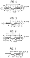
- Fig. 2 is a sectional view of a boundary portion between adjacent cylinder bore holes 2A, 2B in the elastic metallic plate 1 taken along a line connecting the centers of these holes 2A, 2B, i.e. a sectional view of the portion of the elastic metallic plate 1 which is between cylinder bore holes 2.
- the boundary portions between the other adjacent cylinder bore holes are also formed to have identical cross section as a matter of course.
- Fig. 3 is a sectional view of the metallic gasket taken along the line connecting the cylinder bore hole 2A and an end portion, i.e. an edge portion of the elastic metallic plate 1.
- the portion of the metallic plate 1 which is between the cylinder bore hole 2D on the opposite side of the hole 2A and the relative edge portion of the metallic plate 1 is also formed to have an identical cross section. Not only these portions but also the portions of the elastic metallic plate which are around the cylinder bore holes 2 except the regions thereof between the same holes 2 are also formed to have an identical cross section as a matter of course.
- the portions of the elastic metallic plate 1 constituting the metallic gasket which are close to and around the cylinder bores 2 are provided with cross-sectionally cone-shaped beads 4 which are formed concentrically with and which annularly surround the cylinder bore holes 2 (when the beads are generally referred to, they are designated by a reference numeral 4).
- each bead 4 starts in a position which is a predetermined distance L 2 away from the inner circumferential edge of a cylinder bore hole 2, for example about 2.9 mm, and extends in a radial direction so that the bead 4 has a predetermined width L 3 of about 2 mm, the height H of the bead 4 being 0.2 - 0.25 mm.
- a distance L 1 between adjacent cylinder bore holes 2 is, for example, about 7.8 mm.
- a bead 4A around the cylinder bore hole 2A and a bead 4B around the cylinder bore hole 2B are piled up at the adjoining portions thereof to be formed into one bead 4. These portions of adjacent beads 4 may be formed so as to be spaced from each other by a very short distance without lying one upon the other.
- folded portions 5A, 5B are formed so that the folded portions do not lie on the radially inner parts of the bead 4 (when the folded portions are generally referred to, they are designated by a reference numeral 5).
- the width L 4 of each folded portion is, for example, about 2.5 mm.
- the above-described metallic gasket can be manufactured through the following steps.
- various kinds of holes including cylinder bore holes are formed in a metallic plate of a predetermined thickness t .
- Beads 4 are then molded at the portions of the metallic plate which are spaced radially outward from and extend along the circumferences of the cylinder bore holes 2.
- the portions of the metallic plate which are around adjacent cylinder bore holes 2 are folded in the radially outward direction with respect to the holes 2 to form folded portions 5.
- the thickness of the folded portions 5 thus formed is 2t.
- the metallic plate on which the folded portions 5 have been formed is heat treated so as to regulate the hardness of the metallic plate, whereby an elastic metallic plate 1 is obtained.
- the elastic metallic plate 1 constituting a folded portion-carrying metallic gasket is heat treated in this final step so that the hardness thereof becomes, for example, not lower than Hv 350.
- the rigidity of a cylinder head is low as compared with that of a cylinder block.
- the portions of a metallic gasket which are between adjacent cylinder bore holes 2 are liable to be strained most largely due to fluctuations in load in the explosion and expansion strokes in the combustion cycle of the engine. Therefore, the sealing function of the metallic gasket tends to deteriorate most significantly at these portions.
- the precompression compression carried out in advance of the compression for combining the opposed surfaces of the cylinder head and cylinder body
- the precompression is carried out so that, if the thickness of the metallic plate is set to t , the thickness 2t 1 of the part between adjacent cylinder bore holes 2 becomes smaller than that 2t of a folded portion of the metallic plate by ⁇ , and the thickness 2t 2 of the parts which are other than the parts between adjacent cylinder bore holes 2 is smaller than that 2t of a folded portion by ⁇ .
- the thickness 2t 1 of the part of a folded portion which is between adjacent cylinder bore holes in a region a between the same holes is set to, for example, 0.15 mm, and this thickness gradually decreases in the regions b extending on both sides of the region a , the thickness 2t 2 of the parts of the folded portion which are in the area other than the area between adjacent bores 2 in the regions c extending arcuately on both sides of the regions b being set to, for example, 0.12 mm.
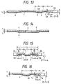
- the values of both ⁇ and ⁇ can be changed in accordance with the position around the cylinder bore hole 2 as shown in Figs. 8 and 9.
- auxiliary metallic plates 8 having a thickness t 4 , which is smaller than that t of the elastic metallic plate 1, are attached to the surfaces, which are on the same side as those of the top ends of the projecting portions of the beads 4, of the parts on the radially outer side of the beads 4.
- the auxiliary metallic plates 8 are provided for the purpose of regulating the difference in thickness between the portions of the metallic plate which are around the cylinder bore holes 2 and those thereof which are on the radially outer side of the beads 4.
- the auxiliary metallic plates 8 are provided on the flat portions of the surface on the same side as the top ends of the projecting portions of the beads 4 so as to reduce the difference in height between the folded portions 5 and the parts of the metallic plate which are on the radially outer side of the beads 4.
- this gasket soft metallic plates 7A, 7B (when they are generally referred to, they will be designated by a reference numeral 7) of a thickness t 3 of, for example, 100-200 ⁇ are held in folded portions 5. Therefore, the thickness of the folded portions 5 on an elastic metallic plate 1 which has been precompressed is 2t + t 3 - ⁇ at the parts thereof which are between cylinder bore holes 2, and 2t + t 3 - ⁇ at the parts thereof which are around the cylinder bore holes but not between the cylinder bore holes 2.
- ⁇ has a value larger than that of ⁇
- the thickness (2t + t 3 - ⁇ ) of the parts of the folded portions which are between the cylinder bore holes 2 is larger than that (2t + t 3 - ⁇ ) of the parts thereof which are around the cylinder bore holes 2 but not between the cylinder bore holes 2.
- the values of both ⁇ and ⁇ can, of course, be changed in accordance with the positions of parts of the folded portions around the cylinder bore holes 2 as shown in Figs. 8 and 9.
- This metallic gasket can be manufactured through the following steps.
- This method of manufacturing metallic gaskets is identical with the metallic gasket manufacturing method of the previously-described gaskets except that the previously described method further includes a step of inserting soft metallic plates 7 in the folded portions 5. Therefore, only that additional step will be described.
- a step of inserting soft metallic plates 7 in the folded portions 5 is added to a step of bending the portions of a metallic plate which are around the cylinder bore holes 2 in the radially outward direction so as to form folded portions 5.
- a compressive force is then applied to the folded portions 5 in which the soft metallic plates 7 have been held so as to mold the folded portions to a preset thickness.
- the metallic plate on which the folded portions have been formed and the soft metallic plates 7 inserted in the folded portions are heat treated to regulate the hardness thereof.
- the soft metallic plates 7 are provided for the purpose of regulating a difference in thickness between the parts of the folded portions around the cylinder bore holes 2 and the parts thereof which are on the radially outer side of the beads 4.
- these soft metallic paltes 7 are provided on the surfaces of the folded portions which are on the same side of the projecting end surfaces of the beads 4 so as to increase the difference in height between the folded portions 5 and the portions of the metallic plate which are on the radially outer side of the beads 4.
- the metallic gasket is inserted between the cylinder head and cylinder block.
- the beads 4 provided around the positions close to the cylinder bore holes 2 in the elastic metallic plate 1 form looped seal portions linearly contacting (before a load is applied) or a narrow surface contacting (after a load is applied) the joint surface of the cylinder head.
- the sealing pressure of the folded portions 5, which form looped seal portions with respect to the opposed surfaces to be combined of the cylinder block and cylinder head, against these cylinder head and cylinder block increases by a level corresponding to the increase in the thickness of the plate, and these two-step looped seal portions prevent the high-temperature and high-pressure combustion gas from flowing along the circumferences of the cylinder bore holes 2 and leaking from the opposed joint surfaces of the cylinder head and cylinder block.
- the folded portions 5 in addition to the beads 4 also contact the opposed joint surfaces to support the tightening force in a shared manner, so that the total compression on the beads 4 is alleviated by as much as a portion shared by the folded portions 5, whereby a load stress occurring in the beads 4 is reduced.
- the thickness 2t 1 of the part of a folded portion which is between adjacent cylinder bore holes in a region a between the same holes is set to 0.37 mm, and this thickness decreases gradually in the regions b extending on both sides of the region a , the thickness 2t 2 of the parts of the folded portion which are in the regions c extending arcuately on both sides of the regions b being set to, for example, 0.32 mm, as shown in Figs. 8 and 9.
- the elastic metallic plate 1 on which the folded portions 5 have been formed is heat treated to regulate the hardness thereof.
- the hardening of the metallic plate is done so that the hardness thereof which is not higher than Hv 200 prior to the formation of the beads 4 attains a level, which corresponds to the kind of the material of the elastic metallic plate 1, after a heat treatment has been finished.
- This gasket is characterized in that regulating plates 6 consisting of metallic plates are laminated on the beads 4 on the elastic metallic plate 1 so as to reinforce the metallic plate and also increase the strength of the beads 4.
- the plate thickness regulating plates 6 are laminated on the surfaces, which are on the same side of the projecting end surfaces of the beads 4, of the portions of the metallic plate which correspond to the beads 4 around the cylinder bore holes 2 and the portions farther away therefrom, i.e. the surfaces of the portions of the metallic plate which correspond to the radially outer side of the holes 2 inclusive of the beads 4.
- the part thereof which is farther away from the bead 4 with respect to both the cylinder bore holes 2A, 2B is the bead 4 itself.
- the regulating plates 6 are laminated on the beads 4 only.
- the regulating plates 6 are formed out of a hard material (Hv 350-500), such as SUS301 or SUS304, and have a thickness t 4 (for example, 0.10-0.200 mm) which is smaller than that t (for example, 0.2-0.3 mm) of the metallic gasket.
- the regulating plates 6 are provided mainly for the purpose of regulating a difference between the thickness of the parts of the elastic metallic plate 1 constituting the metallic gasket which are around the cylinder bore holes 2, i.e the folded portions 5 and that of the parts of the metallic plate 1 which are on the radially outer side of the beads 4.
- the regulating plates 6 are laminated on the projecting end surfaces of the beads 4 so as to minimize the difference in height between the folded portions 5 and the parts of the metallic plate which are farther away from or on the radially outer side of the beads 4. Since the regulating plates 6 consist of the above-mentioned hard material, the strength of the laminated portions including the beads 4 can be increased, and the regulating plates 6 can be provided with the function of protecting the metallic plate against the surface pressure occurring when the beads 4 contact the opposed surfaces to be combined of the cylinder head and cylinder block. As shown in Fig.
- the metallic gasket is deformed so that the portion thereof which is around the hole 3 is recessed slightly (or in the shape of a mountain) from the other planar portion and concentrically with the hole 3, and such a recessed portion enables a sealing effect to be obtained around the hole 3 when the metallic gasket is tightened.
- the beads 4 provided on the portions of the elastic metallic plate 1 which are close to and around the cylinder bore holes 2 contact the joint surface of the cylinder head to form looped seal portions.
- the folded portions 5 form looped seals at the inner side of the looped seal portions based on the beads 4, with respect to the opposed surfaces to be combined of the cylinder block and cylinder head, and the sealing pressure applied to the cylinder head and cylinder block becomes hgiher by a level corresponding to an increase in the thickness of the metallic gasket. Owing to such two-step looped seal portions, the leakage of a high-temperature and high-pressure combustion gas from the cylinder bore holes 2 to the opposed joint surfaces of the cylinder head and cylinder block can be prevented.
- the tightening force is supported in a joint manner on the beads 4 and folded portions 5. Furthermore, since the beads 4 have regulating plates 6 laminated thereon, the height of the beads 4 can be reduced by a level corresponding to the thickness of the regulating plates 6. Accoridngly, the stress occurring in the beads 4 during a tightening operation is further reduced, and the total compression is prevented. Even if the minimized repeated stress mentioned above is imparted to the metallic gasket due to the fluctuation of load during the operation of the engine, the occurrence of permanent strain and cranks in the beads 4 can be prevented since the load stress occurring in the beads 4 is reduced.
- the thickness of the folded portions 5 on an elastic metallic plate which has been precompressed is 2t + t 3 - ⁇ at the parts thereof which are between cylinder bore holes 2, and 2t + t 3 - ⁇ at the parts thereof which are around the cylinder bore holes but not between the cylinder bore holes 2. Since ⁇ has a value larger than that of ⁇ , the thickness (2t + t 3 - ⁇ ) of the parts of the folded portions which are between the cylinder bore holes 2 becomes larger than that (2t + t 3 - ⁇ ) of the parts thereof which are around the cylinder bore holes 2 but not between the cylinder bore holes 2.
- the soft metallic plate 7 can be modified variously. Namely, the values of a and ⁇ can be changed in accordance with the position of the portion of the metallic gasket which is around a cylinder bore hole as shown in Figs. 8 and 9.
- the soft metallic plates 7 may be provided on the whole circumferential areas of the folded portions 5, or formed so that the thickness of the soft metallic plates 7 is larger at only the parts thereof that are between adjacent cylinder bore holes 2, and smaller at the parts thereof which are other than the parts between adjacent cylinder bore holes 2, or provided on only the parts thereof which are between adjacent cylinder bore holes 2.
- the soft metallic plates 7 are inserted in the folded portions 5 in the step of forming the folded portions 5, after the regulating plates 6 have been laminated on the elastic metallic plate 1. A compressive force is then applied to the folded portions 5 so as to mold the same to a preset thickness. Finally, the elastic metallic plate 1 on which the folded portions 5 have been formed and the soft metallic plates 7 held in the folded portions 5 are heat treated to regulate the hardness thereof.
- the soft metallic plates 7 are provided for the purpose of regulating a difference in thickness between the parts of the folded portions around the cylinder bore holes 2 and the parts thereof which are on the radially outer side of the beads 4. For example, when the thickness of the folded portions decreases largely at the parts thereof which are around the cylinder bore holes 2 due to the precompression of the folded portions, these soft metallic plates 7 are laminated on the surfaces of the folded portions which are on the same side of the projecting end surfaces of the beads 4, and held in the folded portions 5, whereby a difference in height between the folded portions 5 and the portions of the metallic plate which are on the radially outer side of the beads 4 is increased.
- This embodiment is identical to the gasket shown in Figures 4 and 5 except that it includes an example of beads 4, in which the shape of the portions of the beads 4 which are around the cylinder bore holes 2 but not between adjacent cylinder bore holes is modified.
- the portions of the beads 4 which are in such areas, and which have a radial width of d, are flattened at the projecting top parts thereof, and the spring constant cf these portions is set smaller correspondingly. Since the shape of the portions of the heads 4 which are between adjacent cylinder bore holes 2 is identical with that of the corresponding portions in that gasket previously-described in relation to Figures 4 and 5, unnecessary duplication of description will be omitted.
Landscapes
- Engineering & Computer Science (AREA)
- General Engineering & Computer Science (AREA)
- Mechanical Engineering (AREA)
- Gasket Seals (AREA)
Claims (11)
- Metallische Dichtung mit einer elastischen Metallplatte (1) aus einem elastischen metallischen Material, die mit ebenen Oberflächen, in der elastischen Metallplatte (1) ausgebildeten Zylinderbohrungsöffnungen (2) sowie Wülsten (4) versehen ist, die an denjenigen Teilen der Metallplatte (1) ausgebildet sind, die um den gesamten Umfangsrand jeder Zylinderbohrungsöffnung (2) angeordnet sind, wobei die Wülste (4) Rippenteile bilden, die aus einer der Seiten der ebenen Oberflächen vorstehen, sowie gefalzte Teile (5), die durch Umbiegen derjenigen Teile der elastischen Metallplatte (1), die den ganzen Umfang jeder Zylinderbohrungsöffnung (2) umgeben, auf die Oberfläche der Metallplatte (1) gebildet sind, auf der sich die Rippenteile der Wülste (4) erstrecken, derart, daß die gefalzten Teile (5) sich nicht mit den Wülsten (4) überlappen, wobei die gefalzten Teile (5) so geformt sind, daß die Summe der Dicke jedes gefalzten Teiles (5) und derjenigen der elastischen Metallplatte (1) kleiner ist als die Höhe jedes wulsttragenden Teiles der Metallplatte (1), um eine auf die Wülste (4) ausgeübte Kompressionskraft genau einzustellen und das volle Zusammendrücken der Wülste (4) zu verhindern, dadurch gekennzeichnet, daß nur ein Wulst (4) um jede der Zylinderbohrungsöffnungen (2) ausgebildet ist, die gefalzten Teile (5) derart geformt sind, daß ihre ganze gefalzte Oberfläche in Berührung mit der Oberfläche der elastischen Metallplatte (1) im nicht belasteten Zustand kommt, daß die elastische Metallplatte (1) nach dem Ausbilden der gefalzten Teile (5) auf der elastischen Metallplatte (1) wärmebehandelt wurde, und daß die Wülste (4) im Querschnitt bogenförmig vorstehende Rippenteile an denjenigen ihrer Abschnitte aufweisen, die zwischen benachbarten Zylinderbohrungsöffnungen (2) liegen, sowie im Querschnitt flach vorstehende Rippenteile an denjenigen ihrer Abschnitte, die nicht die zwischen benachbarten Zylinderbohrungsöffnungen (2) angeordnete Abschnitte sind.
- Metallische Dichtung nach Anspruch 1, bei der die gefalzten Teile (5) mit im wesentlichen der gleichen Dicke um den ganzen Umfang jeder Zylinderbohrungsöffnung (2) ausgebildet sind.
- Metallische Dichtung nach Anspruch 1, bei der die gefalzten Teile (5) mit einer größeren Dicke in denjenigen Abschnitten derselben ausgebildet sind, die zwischen den Zylinderbohrungsöffnungen (2) liegen, und mit einer geringeren Dicke in den übrigen Abschnitten derselben.
- Metallische Dichtung nach einem der vorangehenden Ansprüche, bei der beide Oberflächen der elastischen Metallplatte (1) mit einem nichtmetallischen Material, wie hitze- und ölbeständigem Gummi oder einem hitze- und ölbeständigen Harz, beschichtet sind.
- Metallische Dichtung nach einem der vorangehenden Ansprüche, bei der auf der gleichen Seite wie die vorstehenden Endflächen der Wülste (4) zusätzliche Metallplatten (8) auf die ebenen Oberflächen der elastischen Metallplatte (1) aufgeschichtet sind, die auf der radialen Außenseite der Wülste (4) zur Regulierung der Dicke der elastischen Metallplatte (1) vorgesehen sind.
- Metallische Dichtung nach einem der vorangehenden Ansprüche, mit weichen Organen (7), die in den gefalzten Teilen (5) der elastischen Metallplatte (1) vorgesehen sind.
- Metallische Dichtung nach Anspruch 6, bei der die weichen Organe (7) um den gesamten Umfang jeder Zylinderbohrungsöffnung (2) vorgesehen sind und gleichförmige Dicke besitzen.
- Metallische Dichtung nach Anspruch 6, bei der die weichen Organe (7) in denjenigen Abschnitten der gefalzten Teile (5) vorgesehen sind, die zwischen benachbarten Zyliderbohrungsöffnungen (2) liegen, wobei in den anderen Abschnitten derselben keine weichen Organe vorgesehen sind.
- Metallische Dichtung nach Anspruch 6, bei der die Dicke der weichen Organe (7), die in den gefalzten Teilen (5) vorgesehen sind, in den zwischen benachbarten Zylinderbohrungsöffnungen (2) gelegenen Abschnitten größer ist als in den übrigen Abschnitten derselben.
- Metallische Dichtung nach einem der Ansprüche 6 bis 9, bei der die weichen Organe (7) aus einem der Materialien gebildet sind, welche eine Graphitschicht, eine Aramid-Schlagschicht, ein Harz sowie eine Gummiart umfassen.
- Metallische Dichtung nach einem der vorangehenden Ansprüche, mit Regulierplatten (6), die aus einem metallischen Material bestehen, das auf die vorstehenden Endflächen der Wülste (4) und auf die Oberflächen derjenigen Abschnitte der elastischen Metallplatte (1) aufgeschichtet ist, welche sich von den Wülsten (4) radial nach außen erstrecken.
Applications Claiming Priority (4)
| Application Number | Priority Date | Filing Date | Title |
|---|---|---|---|
| JP30629590A JP2930699B2 (ja) | 1990-11-14 | 1990-11-14 | 金属製ガスケット及びその製造方法 |
| JP306295/90 | 1990-11-14 | ||
| JP156189/91 | 1991-05-31 | ||
| JP03156189A JP3086008B2 (ja) | 1991-05-31 | 1991-05-31 | 金属製ガスケット |
Publications (3)
| Publication Number | Publication Date |
|---|---|
| EP0486255A2 EP0486255A2 (de) | 1992-05-20 |
| EP0486255A3 EP0486255A3 (en) | 1992-12-02 |
| EP0486255B1 true EP0486255B1 (de) | 1996-10-23 |
Family
ID=26484002
Family Applications (1)
| Application Number | Title | Priority Date | Filing Date |
|---|---|---|---|
| EP19910310422 Expired - Lifetime EP0486255B1 (de) | 1990-11-14 | 1991-11-12 | Metalldichtung |
Country Status (2)
| Country | Link |
|---|---|
| EP (1) | EP0486255B1 (de) |
| DE (2) | DE486255T1 (de) |
Families Citing this family (8)
| Publication number | Priority date | Publication date | Assignee | Title |
|---|---|---|---|---|
| DE69217136T2 (de) * | 1991-07-17 | 1997-06-19 | Nippon Gasket Kk | Metalldichtung |
| JP2844501B2 (ja) * | 1991-08-21 | 1999-01-06 | 日本ガスケット株式会社 | 金属製ガスケットおよびその製造方法 |
| JP2841250B2 (ja) * | 1991-09-05 | 1998-12-24 | 日本ガスケット株式会社 | 金属製ガスケット及びその製造方法 |
| JPH0734257U (ja) * | 1993-12-01 | 1995-06-23 | 石川ガスケット株式会社 | シリンダヘッドガスケット |
| US5906376A (en) * | 1997-04-24 | 1999-05-25 | Ishikawa Gasket Co., Ltd. | Metal gasket with locally heated-treating bead |
| JP3113642B2 (ja) | 1999-02-01 | 2000-12-04 | 石川ガスケット株式会社 | 金属積層形ガスケット |
| JP2001280502A (ja) * | 2000-03-29 | 2001-10-10 | Nippon Gasket Co Ltd | 単層金属製ガスケット |
| JP4017868B2 (ja) | 2002-01-09 | 2007-12-05 | 石川ガスケット株式会社 | ガスケット |
Family Cites Families (2)
| Publication number | Priority date | Publication date | Assignee | Title |
|---|---|---|---|---|
| US3053544A (en) * | 1958-10-24 | 1962-09-11 | Chrysler Corp | Gasket |
| DE69108628T2 (de) * | 1990-07-26 | 1995-08-31 | Taiho Kogyo Co Ltd | Metalldichtung. |
-
1991
- 1991-11-12 DE DE1991310422 patent/DE486255T1/de active Pending
- 1991-11-12 DE DE1991622838 patent/DE69122838T2/de not_active Expired - Fee Related
- 1991-11-12 EP EP19910310422 patent/EP0486255B1/de not_active Expired - Lifetime
Also Published As
| Publication number | Publication date |
|---|---|
| DE69122838T2 (de) | 1997-04-03 |
| DE486255T1 (de) | 1992-10-15 |
| DE69122838D1 (de) | 1996-11-28 |
| EP0486255A3 (en) | 1992-12-02 |
| EP0486255A2 (de) | 1992-05-20 |
Similar Documents
| Publication | Publication Date | Title |
|---|---|---|
| EP0523946B1 (de) | Metalldichtung | |
| JP3142155B2 (ja) | 金属製ガスケット | |
| EP0528698B1 (de) | Metalldichtung und Verfahren zu deren Herstellung | |
| US5791659A (en) | Metal gasket | |
| US5690343A (en) | Metal gasket | |
| EP0494489B2 (de) | Metallische Abdichtung | |
| JPH0495668A (ja) | マニホルド用金属ガスケット | |
| US6457724B2 (en) | Metallic gasket | |
| US6164662A (en) | Metal gasket | |
| US6517084B2 (en) | Cylinder head gasket with partial seal coating | |
| JPH04134958U (ja) | 金属積層形ガスケツト | |
| US6135459A (en) | Metal gasket | |
| US5879011A (en) | Laminated metal gasket for a cylinder block of an engine | |
| EP0486255A2 (de) | Metalldichtung | |
| JP2844500B2 (ja) | 金属製ガスケット | |
| EP0845621B1 (de) | Metalldichtung | |
| JP2930699B2 (ja) | 金属製ガスケット及びその製造方法 | |
| JP2930779B2 (ja) | 金属製ガスケット | |
| EP0695897A1 (de) | Metalldichtung für Motoren mit Wirbelkammer | |
| JP3086008B2 (ja) | 金属製ガスケット | |
| JPH0313556Y2 (de) | ||
| JP2000329232A (ja) | 金属製ガスケット | |
| JP3420297B2 (ja) | 金属積層型ガスケット | |
| JP7076775B2 (ja) | 金属ガスケット | |
| JP2596197Y2 (ja) | シリンダヘッドガスケット構造 |
Legal Events
| Date | Code | Title | Description |
|---|---|---|---|
| PUAI | Public reference made under article 153(3) epc to a published international application that has entered the european phase |
Free format text: ORIGINAL CODE: 0009012 |
|
| AK | Designated contracting states |
Kind code of ref document: A2 Designated state(s): DE GB |
|
| PUAL | Search report despatched |
Free format text: ORIGINAL CODE: 0009013 |
|
| DET | De: translation of patent claims | ||
| AK | Designated contracting states |
Kind code of ref document: A3 Designated state(s): DE GB |
|
| 17P | Request for examination filed |
Effective date: 19930527 |
|
| 17Q | First examination report despatched |
Effective date: 19950118 |
|
| GRAG | Despatch of communication of intention to grant |
Free format text: ORIGINAL CODE: EPIDOS AGRA |
|
| GRAH | Despatch of communication of intention to grant a patent |
Free format text: ORIGINAL CODE: EPIDOS IGRA |
|
| GRAH | Despatch of communication of intention to grant a patent |
Free format text: ORIGINAL CODE: EPIDOS IGRA |
|
| GRAA | (expected) grant |
Free format text: ORIGINAL CODE: 0009210 |
|
| AK | Designated contracting states |
Kind code of ref document: B1 Designated state(s): DE GB |
|
| REF | Corresponds to: |
Ref document number: 69122838 Country of ref document: DE Date of ref document: 19961128 |
|
| PLBQ | Unpublished change to opponent data |
Free format text: ORIGINAL CODE: EPIDOS OPPO |
|
| PLBI | Opposition filed |
Free format text: ORIGINAL CODE: 0009260 |
|
| PLBF | Reply of patent proprietor to notice(s) of opposition |
Free format text: ORIGINAL CODE: EPIDOS OBSO |
|
| 26 | Opposition filed |
Opponent name: ELRING KLINGER GMBH Effective date: 19970722 |
|
| PLBF | Reply of patent proprietor to notice(s) of opposition |
Free format text: ORIGINAL CODE: EPIDOS OBSO |
|
| PLBF | Reply of patent proprietor to notice(s) of opposition |
Free format text: ORIGINAL CODE: EPIDOS OBSO |
|
| PLBO | Opposition rejected |
Free format text: ORIGINAL CODE: EPIDOS REJO |
|
| PLBN | Opposition rejected |
Free format text: ORIGINAL CODE: 0009273 |
|
| STAA | Information on the status of an ep patent application or granted ep patent |
Free format text: STATUS: OPPOSITION REJECTED |
|
| 27O | Opposition rejected |
Effective date: 20000207 |
|
| REG | Reference to a national code |
Ref country code: GB Ref legal event code: IF02 |
|
| PGFP | Annual fee paid to national office [announced via postgrant information from national office to epo] |
Ref country code: GB Payment date: 20060908 Year of fee payment: 16 |
|
| PGFP | Annual fee paid to national office [announced via postgrant information from national office to epo] |
Ref country code: DE Payment date: 20061221 Year of fee payment: 16 |
|
| GBPC | Gb: european patent ceased through non-payment of renewal fee |
Effective date: 20071112 |
|
| PG25 | Lapsed in a contracting state [announced via postgrant information from national office to epo] |
Ref country code: DE Free format text: LAPSE BECAUSE OF NON-PAYMENT OF DUE FEES Effective date: 20080603 |
|
| PG25 | Lapsed in a contracting state [announced via postgrant information from national office to epo] |
Ref country code: GB Free format text: LAPSE BECAUSE OF NON-PAYMENT OF DUE FEES Effective date: 20071112 |