EP0486313B1 - Connecteur pour câblage dans un véhicule - Google Patents
Connecteur pour câblage dans un véhicule Download PDFInfo
- Publication number
- EP0486313B1 EP0486313B1 EP19910310542 EP91310542A EP0486313B1 EP 0486313 B1 EP0486313 B1 EP 0486313B1 EP 19910310542 EP19910310542 EP 19910310542 EP 91310542 A EP91310542 A EP 91310542A EP 0486313 B1 EP0486313 B1 EP 0486313B1
- Authority
- EP
- European Patent Office
- Prior art keywords
- connector
- movable piece
- vehicle
- locking key
- hole
- Prior art date
- Legal status (The legal status is an assumption and is not a legal conclusion. Google has not performed a legal analysis and makes no representation as to the accuracy of the status listed.)
- Expired - Lifetime
Links
Images


Classifications
-
- H—ELECTRICITY
- H01—ELECTRIC ELEMENTS
- H01R—ELECTRICALLY-CONDUCTIVE CONNECTIONS; STRUCTURAL ASSOCIATIONS OF A PLURALITY OF MUTUALLY-INSULATED ELECTRICAL CONNECTING ELEMENTS; COUPLING DEVICES; CURRENT COLLECTORS
- H01R13/00—Details of coupling devices of the kinds covered by groups H01R12/70 or H01R24/00 - H01R33/00
- H01R13/73—Means for mounting coupling parts to apparatus or structures, e.g. to a wall
- H01R13/74—Means for mounting coupling parts in openings of a panel
Definitions
- the present invention relates to a connector for wiring in a vehicle, and more particularly, to a vehicle wiring connector which can be firmly attached to a vehicle panel by a simple operation.
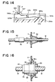
- Typical of the connectors conventionally used for wiring in automobiles are the pair of connectors as shown in Fig. 15, wherein one connector 35 is attached to a terminal end of a harness W and the other connector 40 is attached to a terminal end of a harness W′.
- the harness W is passed through a grommet 30 and a silencing cap 31 and thereafter, fitted in the front end opening portion of the grommet 30.
- the grommet 30 is the fitted in a hole "a" in the vehicle panel "A” and a sound baffle 31 is fitted into the front end opening of the grommet 30. Thereafter, the connector 35 and the connector 40 disposed away from the vehicle panel "A" are electrically connected.
- FIG. 16 Another known pair of connectors is shown in Fig. 16, wherein one connector 35 attached to a terminal end of a harness W has forwardly inclined latching arms 36, 36 provided with engagement protrusions 36a, 36a, and the other connector 40 is attached to a terminal end of a harness W′.
- a grommet 30 is fitted around the periphery of the rear end of the connector 35.
- the engagement protrusions 36a, 36a of the latching arms 36, 36 provided on the connector 35 are forcibly pressed into a hole "a" in the vehicle panel "A”, to thereby simultaneously attach the connector 35 and the grommet 30 to the vehicle panel "A", and thereafter, the connector 40 is connected to the connector 35.
- the grommet 30 and the connector 35 are fitted simultaneously to the vehicle panel “A” by press-fitting the engagement protrusions 36a, 36a formed at the front ends of the latching projections 36, 36 provided on the connector 35 into the hole “a" in the vehicle panel “A”, and thus the connecting of the connectors 35 and 40 can be done with one hand, and accordingly, the work efficiency is improved.
- the connection shown in Fig. 16 if a mechanical pushing force, etc., is exerted in the axial direction on the connector 35, the connector 35 is very easily detached from the vehicle panel "A".
- An object of the present invention is to provide a vehicle wiring connector providing a superior work efficiency and able to be securely and firmly attached to the vehicle panel.
- the present invention provides a first connector for wiring in a vehicle comprising: a connector body consisting of a male or a female connector attached to a terminal end of a harness; engagement projections formed at the outer wall surface of the connector body and engageable with the two side edges of a hole made in a vehicle panel; and characterized by a upwardly inclined movable piece formed at the outer wall surface of the connector body and pressed into contact with the inside surface of the hole in the panel by a repulsion spring force thereof to thereby engage the engagement projections with the hole in the vehicle panel.
- grommet e.g., a rubber grommet
- grommet is attached to the periphery of the one of the connector bodies.
- the engagement projections of the connector body engage with the two side edges of the hole in the vehicle panel, the upwardly inclined movable piece is pressed into contact with the inside surface of the hole in the panel, and due to the repulsion spring force thereof, the engagement projections are securely and firmly engaged with the edges of the hole in the vehicle panel.
- the present invention provides a second connector for wiring in a vehicle comprising: a connector body consisting of a male or a female connector attached to a terminal end of a harness; engagement projections formed at the outer wall surface of the connector body and engageable with the two side edges of a hole made in a vehicle panel; characterized by a movable piece formed at the outer wall surface of the connector body and pressed into contact with the inside surface of the hole in the panel; a locking key insertion portion formed under the movable piece; and a locking key to be inserted into the locking key insertion portion to lock the movable piece and firmly engage the engagement projections with the hole in the vehicle panel.
- a third connector is also realized according to claim 5.
- the movable piece is provided with a repulsion spring force sufficient to press the movable piece into contact with the inside surface of the hole in the vehicle panel to thereby firmly engage the engagement projections with the hole in the vehicle panel.
- the movable piece is provided with a stopper projection formed at the base end thereof, such that the front end of the locking key abuts against the stopper projection.
- a grommet preferably a rubber grommet, is attached to the periphery of one of the connector bodies.
- the engagement projections of the connector body engage with the two side edges of the hole in the vehicle panel, and the movable piece is pressed into contact with the inside surface of the hole in the vehicle panel. Then, to the repulsion spring force of the movable piece, the engagement projections are firmly engaged with the two side edges of the hole in the vehicle panel. Thereafter, locking key is inserted into the locking key insertion portion, to thereby stop any movement of the movable piece to thus securely and firmly fix the connector to the vehicle panel.
- the front end of the locking key abuts against the stopper projection provided at the base end of the movable piece, and thus cannot be fully inserted into the locking key insertion portion, and accordingly, it can be detected that the connector is not properly attached to the vehicle panel.
- the rubber grommet is fitted tightly to the vehicle panel, and thus prevents the entry of noise, rain water, and dust, etc., from the engine compartment to the passenger compartment of the vehicle.
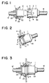
- 1 is a female connector comprised of a connector body 50
- 2 is a fitting hole in which the front end of the opposing male connector 10 is fitted
- 3 is a cutaway portion opening into the fitting hole 2
- 4 is an upwardly inclined movable piece vertically and movably supported at the outer wall surface of end of the cutaway portion 3.
- the upwardly inclined movable piece 4, as shown in Fig. 2 is pressed into contact with the inside surface of a hole "a" in a vehicle panel "A”, and due to a repulsive spring force thereof, causes later-mentioned engagement projections 5 and 6 to be fully engaged with the two side edges of the hole "a” in the panel.
- Reference numerals 5 and 6 show engagement projections formed at the front end of the connector body 50.
- the engagement projections 5 and 6 are designed in such a manner that they are engaged with the two side edges on both sides of the hole "a”, respectively, in the vehicle panel "A”.
- the connector body 50, the engagement projections 5 and 6, and the upper inclined movable piece 4 are formed as a single body from a synthetic resin.
- positions at which the upwardly inclined movable piece 4 and the engagement projections 5 and 6 are provided are not limited and the design may be modified according to need.
- Reference numeral 10 denotes a male connector comprised of a connector body 52 and a flange portion 11 provided at the outer peripheral surface of rear end of the connector body 52.
- reference numeral 20 denotes a rubber grommet.
- the rubber grommet 20 is provided with a fitting groove 21 which fits detachably over the flange portion 11 provided at the outer peripheral surface of the rear end of the male connector 10 and has a suction cup shaped tight-fitting portion 22 formed at the front end.
- the female connector 1 when connecting, for example, a harness W disposed at the passenger compartment side and a harness W′ disposed in the engine compartment, as shown in Fig. 2, the female connector 1 is connected to the terminal end of the harness W disposed in the passenger compartment, is inclined to press the front end of the upwardly inclined movable piece 4 into contact with the inside surface of the hole "a" in the vehicle panel "A” to thereby bend the upwardly inclined movable piece 4 and force it inside the cutaway portion 3, or the upwardly inclined movable piece 4 can be manually forced into the cutaway portion 3, and accordingly, the engagement projections 5 and 6 are engaged with the two side edges of the hole "a" in the panel A. Therefore, as shown in Fig.
- the male connector 10 attached to the grommet 20 is inserted into the fitting hole 2 of the female connector 1, whereby the harness W disposed in the passenger compartment and the harness W′ disposed in the engine compartment are electrically connected, and the suction cup shaped tight fitting portion 22 provided at the front end of the grommet 20 is tightly adhered to the vehicle panel "A", to thereby completely prevent the entry of noise, rain water, and dust, etc., from the engine compartment to the passenger compartment of the vehicle.
- any movement of the upwardly inclined movable piece 4 provided in the female connector 1 is prevented by the outer wall surface of the male connector 10, as shown in Fig. 3, and therefore, the female connector 1 is securely and firmly fixed to the vehicle panel "A", and will not be detached therefrom even if a mechanical tensile force, etc. is exerted on the harness W.
- the outer wall surface of the front end of the female connector 1 is provided with an upwardly inclined movable piece 4 and engagement projections 5 and 6, and the grommet 20 is attached to the male connector 10 to be connected to the female connector 1, but the present invention is not limited to the above embodiment as it is obviously possible to provide the upwardly inclined movable piece and the engagement projections at the outer wall surface of the front end of the male connector 10, and to attach the grommet to the female connector 1 to be connected to the male connector 10.
- the female connector 1 not only can the female connector 1 be securely attached to the vehicle panel “A” by a simple operation of just inserting the female connector 1 into the hole “a” in the vehicle panel “A”, against the spring force of the upwardly inclined movable piece 1 provided in the female connector 1, to thereby engage the engagement projections 5 and 6 with the edges of the hole “a” in the panel “A”, but also the opposing male connector 10 can be connected to the female connector 1 with one hand, and thus the work efficiency is remarkably improved.
- 101 is a female connector comprised of a connector body 150
- 102 is a fitting hole in which the front end of the opposing male connector 110 is fitted
- 103 is a locking key insertion portion separated from the fitting hole 102 by a separating wall as shown in Fig. 5.
- the top surface of the locking key insertion portion 103, as shown in Fig. 5, is open, and at an approximate center point of the locking key insertion portion 103, a movable piece 104 is pivotally supported in a seesaw manner.
- the movable piece 104 has a stopper projection 104a formed at the base end thereof.
- Reference numeral 105 denotes a locking key to be inserted into the locking key insertion portion 103.
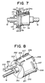
- the locking key 105 is inserted into the locking key insertion portion 103 to prevent any movement of the movable piece 104 after the female connector 101 is attached to the vehicle panel "A", as shown in Fig. 7. Further, when the female connector 101 is not properly attached to the vehicle panel "A", the front end of the locking key 105 abuts against the stopper projection 104a provided at the base end of the movable piece 104, and therefore, the locking key 105 cannot be fully inserted into the locking key insertion portion 103, whereby it can be detected that the female connector 101 is not properly attached to the vehicle panel "A". Note, the locking key 105 may be first provisionally engaged with the female connector 101.
- Reference numerals 106 and 107 denote engagement projections formed at the outer wall surface of the front end of the connector body 150. These engagement projections 106 and 107 are designed in such a manner that they are engaged with the two side edges on both sides of the hole "a" in the vehicle panel "A".
- the connector body 150, the engagement projections 106 and 107, and the movable piece 104 are formed as a single body from a synthetic resin.
- Reference numeral 110 denotes a male connector comprised of a connector body 152 and having a flange portion 111 provided at the outer peripheral surface of the rear end of the connector body 152.
- reference numeral 120 denotes a rubber grommet.
- the rubber grommet 120 is provided with a fitting groove 121 which fits detachably over the flange portion 111 provided at the outer peripheral surface of the top end of the connector body 152.
- the rubber grommet 120 has a suction cup shaped tight-fitting portion 122 at the front end thereof.
- the female connector 1 when connecting, for example, a harness W disposed at the passenger compartment side and a harness W′ disposed in the engine compartment, the female connector 1 is connected to the terminal end of the harness W disposed in the engine compartment, is inclined as shown in Fig. 6 to press the front end of the movable piece 104 into contact with the inside surface of the hole "a" in the vehicle panel "A” to thereby bend the movable piece 104 and force it inside the locking key insertion portion 103, or the movable piece 104 can be manually forced into the locking key insertion portion 103, and accordingly, the engagement projections 106 and 107 are engaged with the two side edges of the hole "a" in the panel "A". Therefore, as shown in Fig.
- the locking key 105 is inserted to the locking key insertion portion 103, whereby any movement of the movable piece 104 is prevented, and thus the female connector 101 is securely and firmly fixed to the vehicle panel "A".
- the front end of the lock key 105 abuts against the projections 104a provided at the base end of the movable piece 104, and accordingly, the locking key 105 cannot be completely inserted to the lock key insertion portion 103, and thus it can be detected that the female connector 101 is not properly attached to the vehicle panel "A".
- the female connector 101 attached to the vehicle panel "A” is provised with a locking key insertion portion 103 and a movable piece 104 supported pivotally in a seesaw manner at an approximate center of the locking key insertion portion 103, the movable piece 104 having a projection 104a formed at the base end thereof, and a locking key 105 is provided to be inserted into the locking key insertion portion 103, but the present invention is not limited to the above embodiment, as obviously the connector may be constructed so that the male connector 110 is attached to the vehicle panel "A” and is provided with a locking key insertion portion for insertion of a locking key, and a movable piece supported in a seesaw manner at the approximate center portion of the locking key insertion portion and having projections formed at the base end thereof, and the grommet can be attached to the female connector 101 to be connected to said male connector 110.
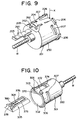
- FIGS. 8 and 9 show an another embodiment, which is a modification of the above-described embodiment shown in Figs. 4 to 7.
- a locking key insertion portion 203 is formed at the rear end of a connector body 250 of a female connector 201 and a locking key 205 is inserted to the insertion portion 203 from the end of the connector body 250 to which a harness W is attached.
- the locking key 250 is provided with first engagement projections 260 which project laterally from both sides of the locking key 205 and are engaged with a movable piece 204 when the locking key 205 is inserted to the connector body 250.
- the movable piece 204 is formed at the outer surface of the connector body 250 and is located over the insertion portion 203.
- the movable piece 204 is pivotally mounted in a seesaw manner at an approximate center of the insertion portion 203.
- a pair of second engagement projections 262 are provided at the rear end of the movable piece 204, and project downward from the sides of the rear end of the movable piece 204.
- the second engagement projections 262 engage with the first engagement projections 260 of the lock key 205 to thereby prevent a detaching of the locking key 205 from the insertion portion 203, after the locking key 205 is fully inserted to the insertion portion 203.
- Engagement projections 206 and 207 are formed at the peripheral surface of the front end of the connector body 250. These engagement projections 206 and 207 are separated from each other by a predetermined distance in an axial direction of the connector body 250, so that the side edges of a hole in a vehicle panel are fitted between the projections 206 and 207.
- Figures. 10 to 13 show an another embodiment, which is a modification of the above-described embodiment shown in Figs. 4 to 7.
- a movable piece 304 is attached to a locking key 305, the movable piece 304 being pivotally supported by supporting pieces 376 in a seesaw manner at the approximate center of the locking key 305.
- the locking key 305, the supporting pieces 376, and the movable piece 304 are formed as one body.
- a locking key insertion portion 303 is formed at the front end of a connector body 350 of a female connector 301, and is separated from a fitting hole 302 by a separating wall 370.
- the locking key insertion portion 303 is provided with an aperture 372 at the top surface thereof, to allow the movable piece 304 of the locking key 305 to be exposed at the outer surface of the connector body 350 when the locking key 305 is fitted into the insertion portion 303.
- Engagement projections 306 and 307 are formed at the peripheral surface of the front end of the connector body 350, and an inside surface of a hole in a vehicle panel (not shown ) is engaged between these projections 306 and 307.
- the insertion portion 303 is provided with a stopper projection 374 on the separating wall 370. The function of the stopper projection 374 will be explained later.
- the locking key 305 is provided with a first upper engagement projection 378 at the base end thereof, and the movable piece 304 is provided with a second upper engagement projection 380 at the base end thereof and a lower engagement projection 382 at the tip end thereof, as shown in Fig. 11.
- the locking key 305 is first partially inserted to the insertion portion 303 of the connection body 350, as shown in Fig. 11. Then, as shown in Fig.12, the front end of the connector body 350 with the locking key 305 is inserted into the hole "a" in the vehicle panel "A", and accordingly, the upper engagement projection 380 of the movable piece 304 is brought into contact with the inner surface of the hole "a” and pressed down. Therefore, the movable piece 304 is pivoted around the supporting piece 376, as a pivotal center, whereby the lower engagement projection 382 is lifted up. In this state, the locking key 305 can be fully inserted to the insertion portion 303 as shown in Fig. 13.
- the upper engagement projection 380 is disengaged from the inner surface of the hole "a" in the panel A and is pushed up by the repulsion spring force thereof, and therefore, the lower engagement projection 382 is pivoted down and engaged with the stopper projection 374, and thus the locking key 305 can not be easily detached from the insertion portion 303.
- the engagement projections 306 and 307 of the connection body 350 are engaged with the two side edges of the hole "a”, and further, the first and second upper engagement projection 378 and 380 are engaged with the two side edges of the hole "a” in the panel A, and accordingly, the connector 301 can not be easily detached from the vehicle panel "A" once it is attached thereto.
- Figure 14 shows an another embodiment, which is a modification of the embodiment shown in Figs. 10 to 13.
- the connectors can be connected simply and swiftly with one hand, and when the connectors are connected, the suction cup shaped tight-fitting portion provided at the front end of the grommet is tightly fitted into the vehicle panel, and thus a great advantage is obtained in that it is possible to completely prevent the entry of noise, rain water, and dust, etc., from the engine compartment to the passenger compartment of the vehicle.
Landscapes
- Details Of Connecting Devices For Male And Female Coupling (AREA)
- Connector Housings Or Holding Contact Members (AREA)
Claims (10)
- Connecteur pour câblage à l'intérieur d'un véhicule, comprenant :
un corps de connecteur (50) constitué d'un connecteur parmi les connecteurs mâle et femelle, fixé à une extrémité d'un faisceau de câbles, et
des saillies d'accrochage (5, 6) formées à une surface de paroi externe du corps (50) de connecteur et destinées à s'accrocher sur deux bords latéraux d'un trou dans un panneau de véhicule, caractérisé par
une pièce mobile (4) inclinée vers le haut, formée à la surface de paroi externe du corps de connecteur (50) et repoussée au contact d'une surface interne du trou (a) formé dans le panneau (A) de véhicule par sa force élastique de répulsion, de manière que les saillies d'accrochage (5, 6) soient accrochées sur le trou (a) du panneau (A) du véhicule. - Connecteur destiné à un câblage dans un véhicule, comprenant :
un corps de connecteur (150) formé d'un connecteur parmi des connecteurs mâle et femelle, fixé à une extrémité d'un faisceau de câbles, et
des saillies d'accrochage (106, 107) formées à une surface de paroi externe du corps de connecteur (150) et destinées à s'accrocher à deux bords latéraux au moins d'un trou (a) d'un panneau (A) du véhicule, caractérisé par
une pièce mobile (104) formée à une surface de paroi externe du corps de connecteur (150) et repoussée au contact d'une surface interne du trou (a) formé dans le panneau (A) du véhicule,
une partie (103) d'introduction d'une clavette de blocage, formée sous la pièce mobile (104), et
une clavette de blocage (105) qui peut être introduite dans la partie (103) d'introduction de clavette de blocage afin qu'elle bloque la pièce mobile (104) et maintienne des saillies d'accrochage (106, 107) au contact du trou (a) formé dans le panneau (A) du véhicule. - Connecteur de câblage pour véhicule selon la revendication 2, dans lequel la pièce mobile (104) est supportée afin qu'elle puisse pivoter à la manière d'une bascule approximativement au centre de la partie d'introduction (103) de la clavette de blocage.
- Connecteur de câblage destiné à un véhicule selon la revendication 2, dans lequel la pièce mobile (104) a une saillie (104a) formant organe d'arrêt, réalisée à une extrémité de base afin qu'une extrémité avant de la clavette de blocage (105) soit en butée contre la saillie (104a) formant organe d'arrêt lorsque le connecteur n'est pas convenablement fixé au panneau (A) du véhicule.
- Connecteur de câblage destiné à un véhicule, comprenant :
un corps de connecteur (350) constitué d'un connecteur choisi parmi les connecteurs mâle et femelle, fixé à une extrémité d'un faisceau de câbles, et
des saillies d'accrochage (306, 307) formées à une surface de paroi externe du corps de connecteur (350) et destinées à s'accrocher à deux bords latéraux au moins d'un trou (a) formé dans un panneau (A) du véhicule, caractérisé par
une partie (303) d'introduction d'une clavette de blocage, formée à une surface de paroi externe du corps de connecteur (350),
une clavette de blocage (305) qui peut être introduite dans la partie (303) d'introduction de clavette de blocage, et
une pièce mobile (304) supportée de manière pivotante au niveau de la clavette de blocage (305) afin qu'elle s'accroche sur le trou (a) formé dans le panneau (A) du véhicule et maintienne les saillies d'accrochage (306, 307) au contact du trou (a). - Connecteur de câblage destiné à un véhicule, selon la revendication 1, 2 ou 5, dans lequel une rondelle (20, 120) formée par une pièce de caoutchouc est fixée à la périphérie dudit corps de connecteur (50, 150, 250) ou de l'autre corps de connecteur (52, 152) afin qu'elle lui soit raccordée électriquement.
- Connecteur de câblage destiné à un véhicule selon la revendication 1, dans lequel le corps de connecteur (50), les saillies d'accrochage (5, 6) et la pièce mobile (4) inclinée vers le haut sont formées en une seule pièce d'une résine de synthèse.
- Connecteur de câblage destiné à un véhicule selon la revendication 2, dans lequel le corps de connecteur (150), les saillies d'accrochage (106, 107), la pièce mobile (104) et la partie d'introduction (103) de la clavette de blocage sont formés en un seul corps de résine de synthèse.
- Connecteur de câblage destiné à un véhicule selon la revendication 2, dans lequel la pièce mobile (104) a une force élastique de répulsion grâce à laquelle la pièce mobile (104) est repoussée au contact de la surface interne du trou (a) formé dans le panneau (A) du véhicule afin qu'elle fasse coopérer les saillies d'accrochage (106, 107) avec le trou (a) formé dans le panneau (A) du véhicule.
- Connecteur de câblage destiné à un véhicule selon la revendication 5, dans lequel la pièce mobile (304) et la clavette de blocage (305) sont formées en une seule pièce de résine de synthèse.
Applications Claiming Priority (4)
| Application Number | Priority Date | Filing Date | Title |
|---|---|---|---|
| JP119135/90U | 1990-11-14 | ||
| JP11913590U JPH0735332Y2 (ja) | 1990-11-14 | 1990-11-14 | コネクタ付きグロメット |
| JP11913690U JPH0735333Y2 (ja) | 1990-11-14 | 1990-11-14 | コネクタ付きグロメット |
| JP119136/90U | 1990-11-14 |
Publications (3)
| Publication Number | Publication Date |
|---|---|
| EP0486313A2 EP0486313A2 (fr) | 1992-05-20 |
| EP0486313A3 EP0486313A3 (en) | 1993-01-13 |
| EP0486313B1 true EP0486313B1 (fr) | 1995-06-07 |
Family
ID=26456929
Family Applications (1)
| Application Number | Title | Priority Date | Filing Date |
|---|---|---|---|
| EP19910310542 Expired - Lifetime EP0486313B1 (fr) | 1990-11-14 | 1991-11-14 | Connecteur pour câblage dans un véhicule |
Country Status (2)
| Country | Link |
|---|---|
| EP (1) | EP0486313B1 (fr) |
| DE (1) | DE69110250T2 (fr) |
Families Citing this family (2)
| Publication number | Priority date | Publication date | Assignee | Title |
|---|---|---|---|---|
| GB9219328D0 (en) * | 1992-09-11 | 1992-10-28 | Amp Gmbh | Automotive door-to-body electrical |
| JP2973866B2 (ja) * | 1995-04-24 | 1999-11-08 | 住友電装株式会社 | 待ち受けコネクタ |
Family Cites Families (4)
| Publication number | Priority date | Publication date | Assignee | Title |
|---|---|---|---|---|
| US2756403A (en) * | 1955-05-13 | 1956-07-24 | Gen Electric | Combined cord connector and strain relief |
| GB909417A (en) * | 1959-05-01 | 1962-10-31 | Smith & Sons Ltd S | Improvements in or relating to securing means for detachably securing an element in a hole in a support |
| GB1190936A (en) * | 1966-11-21 | 1970-05-06 | Pressac Ltd | Improvements in or relating to Sockets for Jack Plugs |
| US3731260A (en) * | 1971-05-06 | 1973-05-01 | Microdot Inc | Socket housing |
-
1991
- 1991-11-14 DE DE1991610250 patent/DE69110250T2/de not_active Expired - Fee Related
- 1991-11-14 EP EP19910310542 patent/EP0486313B1/fr not_active Expired - Lifetime
Also Published As
| Publication number | Publication date |
|---|---|
| DE69110250D1 (de) | 1995-07-13 |
| DE69110250T2 (de) | 1995-10-26 |
| EP0486313A2 (fr) | 1992-05-20 |
| EP0486313A3 (en) | 1993-01-13 |
Similar Documents
| Publication | Publication Date | Title |
|---|---|---|
| US5487680A (en) | Method and structure for fixing a connector to a vehicle body panel | |
| US4721482A (en) | Connector housing | |
| US6439902B1 (en) | Pre-set locks for a connector lever | |
| US5429527A (en) | Connector | |
| US5639256A (en) | Feeder connector | |
| US5827086A (en) | Half-fitting prevention connector | |
| US5088938A (en) | Terminal locking block for electrical connectors | |
| JPH07321478A (ja) | 電気接続箱の防水シール構造 | |
| JP2973866B2 (ja) | 待ち受けコネクタ | |
| US6027364A (en) | Connector fitting construction with side ribs and corresponding side rib-receiving portions | |
| US6321446B1 (en) | Method of fitting connectors and the connectors for use in the method | |
| JPH11233197A (ja) | 電気コネクタ組立体及び電気コネクタ | |
| GB2302767A (en) | Ensuring full coupling of an electrical connector | |
| JPH07288150A (ja) | 防水コネクタのパッキン固定方法及びその構造 | |
| US5772461A (en) | Locking mechanism for interconnecting two mated connectors | |
| JPH11144809A (ja) | コネクタ | |
| JPH0581967U (ja) | コネクタ | |
| US6511029B2 (en) | Bracket for mounting an accessory on vehicle body | |
| US6752655B1 (en) | Method and structure for fixing a locking connector to a vehicle member | |
| JPH1154210A (ja) | コネクタ接続構造 | |
| US5259788A (en) | Connector for wiring in a vehicle | |
| EP0486313A2 (fr) | Connecteur pour câblage dans un véhicule | |
| JP3541695B2 (ja) | パネル取付型コネクタ | |
| EP1206014B1 (fr) | Connecteur électrique pour montage dans une overture d'un panneau | |
| JPH0753269Y2 (ja) | グロメット付きコネクタ |
Legal Events
| Date | Code | Title | Description |
|---|---|---|---|
| PUAI | Public reference made under article 153(3) epc to a published international application that has entered the european phase |
Free format text: ORIGINAL CODE: 0009012 |
|
| AK | Designated contracting states |
Kind code of ref document: A2 Designated state(s): DE FR GB |
|
| PUAL | Search report despatched |
Free format text: ORIGINAL CODE: 0009013 |
|
| AK | Designated contracting states |
Kind code of ref document: A3 Designated state(s): DE FR GB |
|
| 17P | Request for examination filed |
Effective date: 19930312 |
|
| 17Q | First examination report despatched |
Effective date: 19940824 |
|
| GRAA | (expected) grant |
Free format text: ORIGINAL CODE: 0009210 |
|
| AK | Designated contracting states |
Kind code of ref document: B1 Designated state(s): DE FR GB |
|
| REF | Corresponds to: |
Ref document number: 69110250 Country of ref document: DE Date of ref document: 19950713 |
|
| ET | Fr: translation filed | ||
| PLBE | No opposition filed within time limit |
Free format text: ORIGINAL CODE: 0009261 |
|
| STAA | Information on the status of an ep patent application or granted ep patent |
Free format text: STATUS: NO OPPOSITION FILED WITHIN TIME LIMIT |
|
| 26N | No opposition filed | ||
| PGFP | Annual fee paid to national office [announced via postgrant information from national office to epo] |
Ref country code: FR Payment date: 20011113 Year of fee payment: 11 |
|
| PGFP | Annual fee paid to national office [announced via postgrant information from national office to epo] |
Ref country code: GB Payment date: 20011114 Year of fee payment: 11 |
|
| PGFP | Annual fee paid to national office [announced via postgrant information from national office to epo] |
Ref country code: DE Payment date: 20011126 Year of fee payment: 11 |
|
| REG | Reference to a national code |
Ref country code: GB Ref legal event code: IF02 |
|
| PG25 | Lapsed in a contracting state [announced via postgrant information from national office to epo] |
Ref country code: GB Free format text: LAPSE BECAUSE OF NON-PAYMENT OF DUE FEES Effective date: 20021114 |
|
| PG25 | Lapsed in a contracting state [announced via postgrant information from national office to epo] |
Ref country code: DE Free format text: LAPSE BECAUSE OF NON-PAYMENT OF DUE FEES Effective date: 20030603 |
|
| GBPC | Gb: european patent ceased through non-payment of renewal fee | ||
| PG25 | Lapsed in a contracting state [announced via postgrant information from national office to epo] |
Ref country code: FR Free format text: LAPSE BECAUSE OF NON-PAYMENT OF DUE FEES Effective date: 20030731 |
|
| REG | Reference to a national code |
Ref country code: FR Ref legal event code: ST |