EP0486328B1 - Dekorative Handleuchte - Google Patents
Dekorative Handleuchte Download PDFInfo
- Publication number
- EP0486328B1 EP0486328B1 EP91401153A EP91401153A EP0486328B1 EP 0486328 B1 EP0486328 B1 EP 0486328B1 EP 91401153 A EP91401153 A EP 91401153A EP 91401153 A EP91401153 A EP 91401153A EP 0486328 B1 EP0486328 B1 EP 0486328B1
- Authority
- EP
- European Patent Office
- Prior art keywords
- decorative
- light
- torch according
- decorative torch
- grip portion
- Prior art date
- Legal status (The legal status is an assumption and is not a legal conclusion. Google has not performed a legal analysis and makes no representation as to the accuracy of the status listed.)
- Expired - Lifetime
Links
Images


Classifications
-
- F—MECHANICAL ENGINEERING; LIGHTING; HEATING; WEAPONS; BLASTING
- F21—LIGHTING
- F21L—LIGHTING DEVICES OR SYSTEMS THEREOF, BEING PORTABLE OR SPECIALLY ADAPTED FOR TRANSPORTATION
- F21L4/00—Electric lighting devices with self-contained electric batteries or cells
-
- F—MECHANICAL ENGINEERING; LIGHTING; HEATING; WEAPONS; BLASTING
- F21—LIGHTING
- F21S—NON-PORTABLE LIGHTING DEVICES; SYSTEMS THEREOF; VEHICLE LIGHTING DEVICES SPECIALLY ADAPTED FOR VEHICLE EXTERIORS
- F21S10/00—Lighting devices or systems producing a varying lighting effect
- F21S10/002—Lighting devices or systems producing a varying lighting effect using liquids, e.g. water
-
- F—MECHANICAL ENGINEERING; LIGHTING; HEATING; WEAPONS; BLASTING
- F21—LIGHTING
- F21S—NON-PORTABLE LIGHTING DEVICES; SYSTEMS THEREOF; VEHICLE LIGHTING DEVICES SPECIALLY ADAPTED FOR VEHICLE EXTERIORS
- F21S10/00—Lighting devices or systems producing a varying lighting effect
- F21S10/005—Lighting devices or systems producing a varying lighting effect using light guides
-
- F—MECHANICAL ENGINEERING; LIGHTING; HEATING; WEAPONS; BLASTING
- F21—LIGHTING
- F21V—FUNCTIONAL FEATURES OR DETAILS OF LIGHTING DEVICES OR SYSTEMS THEREOF; STRUCTURAL COMBINATIONS OF LIGHTING DEVICES WITH OTHER ARTICLES, NOT OTHERWISE PROVIDED FOR
- F21V21/00—Supporting, suspending, or attaching arrangements for lighting devices; Hand grips
- F21V21/40—Hand grips
- F21V21/406—Hand grips for portable lighting devices
-
- F—MECHANICAL ENGINEERING; LIGHTING; HEATING; WEAPONS; BLASTING
- F21—LIGHTING
- F21V—FUNCTIONAL FEATURES OR DETAILS OF LIGHTING DEVICES OR SYSTEMS THEREOF; STRUCTURAL COMBINATIONS OF LIGHTING DEVICES WITH OTHER ARTICLES, NOT OTHERWISE PROVIDED FOR
- F21V23/00—Arrangement of electric circuit elements in or on lighting devices
- F21V23/04—Arrangement of electric circuit elements in or on lighting devices the elements being switches
- F21V23/0414—Arrangement of electric circuit elements in or on lighting devices the elements being switches specially adapted to be used with portable lighting devices
-
- F—MECHANICAL ENGINEERING; LIGHTING; HEATING; WEAPONS; BLASTING
- F21—LIGHTING
- F21V—FUNCTIONAL FEATURES OR DETAILS OF LIGHTING DEVICES OR SYSTEMS THEREOF; STRUCTURAL COMBINATIONS OF LIGHTING DEVICES WITH OTHER ARTICLES, NOT OTHERWISE PROVIDED FOR
- F21V7/00—Reflectors for light sources
-
- F—MECHANICAL ENGINEERING; LIGHTING; HEATING; WEAPONS; BLASTING
- F21—LIGHTING
- F21W—INDEXING SCHEME ASSOCIATED WITH SUBCLASSES F21K, F21L, F21S and F21V, RELATING TO USES OR APPLICATIONS OF LIGHTING DEVICES OR SYSTEMS
- F21W2121/00—Use or application of lighting devices or systems for decorative purposes, not provided for in codes F21W2102/00 – F21W2107/00
-
- Y—GENERAL TAGGING OF NEW TECHNOLOGICAL DEVELOPMENTS; GENERAL TAGGING OF CROSS-SECTIONAL TECHNOLOGIES SPANNING OVER SEVERAL SECTIONS OF THE IPC; TECHNICAL SUBJECTS COVERED BY FORMER USPC CROSS-REFERENCE ART COLLECTIONS [XRACs] AND DIGESTS
- Y10—TECHNICAL SUBJECTS COVERED BY FORMER USPC
- Y10S—TECHNICAL SUBJECTS COVERED BY FORMER USPC CROSS-REFERENCE ART COLLECTIONS [XRACs] AND DIGESTS
- Y10S362/00—Illumination
- Y10S362/806—Ornamental or decorative
-
- Y—GENERAL TAGGING OF NEW TECHNOLOGICAL DEVELOPMENTS; GENERAL TAGGING OF CROSS-SECTIONAL TECHNOLOGIES SPANNING OVER SEVERAL SECTIONS OF THE IPC; TECHNICAL SUBJECTS COVERED BY FORMER USPC CROSS-REFERENCE ART COLLECTIONS [XRACs] AND DIGESTS
- Y10—TECHNICAL SUBJECTS COVERED BY FORMER USPC
- Y10S—TECHNICAL SUBJECTS COVERED BY FORMER USPC CROSS-REFERENCE ART COLLECTIONS [XRACs] AND DIGESTS
- Y10S362/00—Illumination
- Y10S362/806—Ornamental or decorative
- Y10S362/808—Figure
- Y10S362/809—Terrestrial globe
Definitions
- the present invention relates to a decorative torch capable of illuminating its handle part in a twinkling way in the dark as if stars are shining, and producing a striking effect in a ceremony or the like.
- a flash light or an electric lamp is used to light darkness by activating a lamp installed therein.
- This conventional light is usually used in a case of walking in the night or as a preparation for power failure, since it has limited function.
- a color changeable photo-decorative pencil torch as described in U.S Patent No. 4,858,083 is already known.
- This color changeable photo-decorative pencil torch comprises a transparent hollow body disposed in the front portion of an illuminating source.
- the transparent hollow body contains a liquid and a plurality of small pieces such as aluminium foil contained therein. Therefore, when the small pieces are lit by the illuminating source, these pieces reflects the light as if stars are shining in the hollow body.
- the color changeable decorative torch it can produce a decorative effect different from the conventional electric light.
- this effect is obtained by utilizing light radiated forwardly from the lamp, therefore, is limited to have such effect only in the forward direction.
- the light is radiated from the lamp not only in forward direction but also in side directions, therefore, there is left much room for improving efficiency by utilizing the side or backward light.
- An object of the present invention is, therefore, to present a decorative torch capable of utilizing not only forward light from the lamp, but backward or side light from the lamp for lighting the handle located at rearward direction of the lamp so that it can produce a highly decorative effect.
- the present invention has been made to accomplish the object mentioned above, and is directed to a decorative torch comprising: a grip portion having a transparent hollow body, said grip portion having an axis; an illuminating light source located at one end of said grip portion; a refracting portion arranged in the vicinity of said illuminating light source for refracting light from the side portion of said illuminating light source in the axial direction of said grip portion to the opposite end thereof; a reflecting portion formed on said grip portion for reflecting light from said refracting portion in the radial external direction of said grip portion.
- a part of the light radiated from the illuminating source is refracted by the refracting portion, further guided to another end of the grip. These light will be further reflected by the reflecting portion formed on an inner surface of the grip so as to shine the grip as a whole in a twinkling way.
- Fig. 1 illustrates a first embodiment of a decorative torch of the present invention and reference numeral 1 designates a grip of a decorative torch to be gripped by a person, reference numeral 2 designates a decorative portion detatchably mounted on the upper portion of the grip 1.
- the grip 1 and decorative portion 2 will be described below referring to a partial cross-sectional view of Fig. 2.
- the grip 1 is cylindrically formed from transparent plastic material, which includes a battery case 5 for storing battery cells 4 arranged in series therein.
- a holding member 7 for holding an electric lamp 6 is fixed inside of the upper portion of the grip 1.
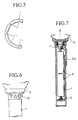
- This holding member 7 is formed from transparent material like plastics in a cylindrical shape as shown in a partial enlarged view Fig. 3.
- Threading portions 8, 9 are formed on an outer surface of the holding member 7 and inner surface of the grip 1 for threading them to each other.
- a tape 10 is wrapped around the upper portion of the grip 1, the inner surface of which is formed to have a mirror surface, for example, by laminating a metal sheet thereto.
- the threaded portions 8, 9 not only securely connect the holding member 7 to the grip 1, also form a refracting portion for refracting the light of the lamp 6 radiated from its side portion 6A, and leading them to the inner and lower portion of the grip 1.
- Fig. 4 a partial enlarged view of a vicinity of the threaded portion 8, 9.
- These threaded portions 8, 9 are formed to have trapezoidal cross sections comprising inclined surfaces respective to the axis of the grip 1 as shown in Fig. 4.
- the light from the side portion 6A of the lamp 6 passes through the holding member 7 as shown by a mark X in Fig. 4, and then they are radiated into random directions through refraction at the threaded portions.
- the light is further reflected by a mirror surface 10A inside of a tape 10 wrapped around the upper portion of the grip 1, and passes through the inside of the grip 1 downwardly as is shown by a mark Y in Fig. 4.
- the recesses 11 are formed in a shape of an asterisk so as to reflect the downward light Y into random directions.
- the recesses 11 reflect the downward light Y as shown by a mark Z in Fig. 4 so as to brighten the grip partially or as a whole as if shining stars are scattered in the grip 1.
- the recesses 11 are formed in a shape of an asterisk, but are not restricted to this shape, and may be formed in any shape such as a special pattern like a flower. A series of letters are also available including the name of the company in a case of advertisement or use for a commemoration gift for the company. An interesting way of use is obtained by forming recesses in a pattern of a map as will be described later referring to Fig. 8 to 11.
- the tape 10 wrapped around the upper portion of the grip renders the light from the holding member 7 not to pass out of the grip 1 by a mirror surface on its inner surface as described above.
- This tape is replaceable with a cylindrically-shaped member fitted to the grip 1.
- the battery case 5 Since the battery case 5 is installed inside the transparent grip 1, it can be seen from the outside. Therefore, by coloring it in a various pattern and colors, a more decorative effect can be obtained. It is also useful to provide the battery case with a slide switch 5A, which can be handled by a finger in order to provide a lamp 6 with a current from the battery cells.
- a hollow space of a cylindrical shape is formed in the holding member 7, and a transparent coloring member 12 is arranged therein.
- This coloring member 12 is formed from a transparent material like plastics for coloring the light from the upper portion 6A of the lamp 6 while it passes therethrough.
- the coloring member 12 is formed smaller in size than the hollow space so that it is slidable along the circumferential direction.
- This coloring member 12 can be designed to have different colors along the circumferential direction so that different colors will appear at different portions of the grip 1 so that it can increase the beauty of light. Therefore, by shaking a decorative torch so as to move the coloring member 12 in rotational manner in the hollow space inside the holding member 7, the colors of the grip will change.
- the brightness of the grip 1 can be changed into an appropriate determined value by controlling the tightening torque.
- An opening 20 is formed at the upper portion of the holding member 7 for holding the lamp 6, and a transparent coloring plate 21 formed in a round plate is arranged therein for coloring the light from the upper portion 6B of the lamp 6 as it passes therethrough.
- This coloring plate 21 is held by a holder fixed around the opening 20 in a manner to permit the coloring plate 21 to rotate along the circumferential direction.
- a supporting member 22 is provided for detatchably supporting a decorative portion 2. Therefore, the coloring plate 21 is lit directly by the upward light which passed through the transparent coloring plate 21.
- the decorative portion 2 formed from a transparent material like plastics into a shape as shown in Fig. 2, comprises a ball body 23, scattering liquid 24 held in the hollow portion in the ball body 23 and a plurality of small pieces 25 dispersed in the scattering liquid 24.
- an organic solvent preferably one, the specific gravity of which is greater than that of water, e.g., trichloroethylene, carbon tetrachloride, chloroform or a homogeneous mixture thereof or with water might be used.
- a doll 26 is positioned at the top of the decorative portion.
- the light from the upper portion 6B of the lamp 6 passes through a flat plate 23A at the bottom of the ball body 23 and reflects off the small pieces 25 drifting among the scattering liquid 24 inside the ball body.
- the light, after entering inside of the ball body 23, will again pass through the ball body 23 to go out of the ball body 23 to illuminate the doll 26 on the ball body 23.
- the coloring plate 21 is formed in a round plate shape, therefore, by coloring the coloring plate 21 differently along its circumferential direction, the decorative portion 2 will be lit in various colors so that it can bring more beautifulness to the decorative portion 2. Further, in that case, by shaking the decorative torch to rotate the transparent coloring plate 21, the colors of the decorative portion 2 will also vary according to the rotation of the coloring plate 21.
- a lamp 6 is located at one end of the grip 1, and the light radiated from side portion 6A of the lamp 6 is refracted by a threaded portion 8, 9 and the inner surface of a tape 10, further guided to another end of the grip 1.
- the light will be further reflected by the recesses 11 formed on an inner surface of the grip 1, and accordingly the grip 1 shines as a whole in a twinkling way.
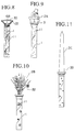
- a decorative torch shown in Fig. 8 is provided with a lens 30 fitted to the holding member 22 for illuminating forward portion directly with light from the upper portion 6B of the lamp 6.
- Light from the side portion 6A is guided to the grip 1 to be refracted by the recesses 11 in the same way as the first embodiment. Therefore, by forming the recesses 11 in a pattern of a map, for instance, showing the way to an emergency exit or a shelter, it is very convenient for a person to escape in a emergency such as fire, earthquake or the like.
- FIG. 9 Another embodiment is shown in Fig. 9, in which a decorative portion 2A is formed in a shape of a doll so that the doll can be illuminated directly by the light from the upper portion 6B of the lamp 6.
- FIG. 10 Another embodiment is shown in Fig. 10, in which a decorative portion 2A is formed in a shape of arranged flowers 32.
- the recesses 11 in a shape of patterns relevant to the decorative portion, for example, a snow flake pattern for a snowman, a flower pattern for a flower arrangement so that it can emphasize the main characteristics of the decorative portion.
- FIG. 11 Another embodiment is shown in Fig. 11, in which a decorative portion 2C is formed in a shape of a sword that can be lit by the upper portion 6B.
Landscapes
- Engineering & Computer Science (AREA)
- General Engineering & Computer Science (AREA)
- Toys (AREA)
- Non-Portable Lighting Devices Or Systems Thereof (AREA)
- Illuminated Signs And Luminous Advertising (AREA)
Claims (19)
- Dekorative Handleuchte mit
einem Griffteil (1) mit einem transparenten hohlen Körper, welcher Griffteil (1) eine Achse aufweist,
einer Beleuchtungslichtquelle (6), die an einem Ende des Griffteils angeordnet ist,
einem Brechungsteil (8, 9), der in der Nähe der Beleuchtungslichtquelle angeordnet ist, um das Licht vom Seitenteil (6A) der Beleuchtungslichtquelle in der axialen Richtung des Griffteils zu dessen gegenüberliegendem Ende zu brechen,
einem reflektierenden Teil (10), der am Griffteil ausgebildet ist, um Licht vom Brechungsteil in der Richtung radial nach außen vom Griffteil zu reflektieren. - Dekorative Handleuchte nach Anspruch 1, welche eine Öffnung (20) aufweist, die an einem Ende des Griffteils angeordnet ist, damit Licht von der Beleuchtungsquelle (6) dort hindurchgehen kann.
- Dekorative Handleuchte nach Anspruch 2, bei der der Brechungsteil (8, 9) eine schräg relativ zur Achse des Griffteils verlaufende Fläche umfaßt.
- Dekorative Handleuchte nach Anspruch 1, bei der die schräg verlaufende Fläche als Gewindeteil ausgebildet ist, der an einer Innenfläche des transparenten hohlen Körpers ausgebildet ist.
- Dekorative Handleuchte nach Anspruch 4, welche eine Halteplatte (7) aufweist, um die Beleuchtungsquelle sicher zu halten, welche Halteplatte aus einem transparenten Material gebildet ist und einen Gewindeteil aufweist, der in den Gewindeteil des transparenten hohlen Körpers geschraubt ist.
- Dekorative Handleucht nach Anspruch 1, welche ein Farbgebungselement (12) aufweist, das zwischen dem Brechungsteil und der Beleuchtungsquelle angeordnet ist, um dem Licht von der Beleuchtungsquelle eine Farbe zu geben.
- Dekorative Handleuchte nach Anspruch 6, bei der das Farbgebungselement (12) hohlzylinderförmig ausgebildet ist.
- Dekorative Handleuchte nach Anspruch 7, bei der das Farbgebungselement (12) um die Achse des transparenten hohlen Körpers drehbar angeordnet ist.
- Dekorative Handleuchte nach Anspruch 8, welche eine Halteplatte (7) aufweist, um sicher die Beleuchtungsquelle zu halten, welche Halteplatte eine Nut aufweist, die in Umfangsrichtung verläuft, um das Farbgebungselement dort entlang gleitend verschiebbar zu halten.
- Dekorative Handleuchte nach Anspruch 1, welche einen dekorativen Teil (2) aufweist, der an einem Ende des Griffteils so angeordnet ist, daß er durch das Licht von der Beleuchtungsquelle über die Öffnung des Griffteils angestrahlt wird.
- Dekorative Handleuchte nach Anspruch 10, bei der der dekorative Teil (2) als ein flüssigkeitsdichtes Gehäuse (23) ausgebildet ist, das eine streuende Flüssigkeit (24) zum Streuen des Lichtes der Beleuchtungsquelle enthält.
- Dekorative Handleuchte nach Anspruch 5, welche ein Farbgebungselement (12) aufweist, das zwischen dem Brechungsteil und der Beleuchtungsquelle angeordnet ist, um dem Licht von der Beleuchtungsquelle eine Farbe zu geben.
- Dekorative Handleuchte nach Anspruch 12, bei der das Farbgebungselement (12) hohlzylinderförmig ausgebildet ist.
- Dekorative Handleuchte nach Anspruch 13, bei der das Farbgebungselement (12) um die Achse des transparenten hohlen Körpers drehbar angeordnet ist.
- Dekorative Handleuchte nach Anspruch 14, bei der die Halteplatte (7) eine Nut aufweist, die in Umfangsrichtung verläuft, um das Farbgebungselement dort entlang gleitend verschiebbar zu halten.
- Dekorative Handleuchte nach Anspruch 5, welche einen dekorativen Teil (2) aufweist, der an einem Ende des Griffteils so angeordnet ist, daß er vom Licht der Beleuchtungsquelle über die Öffnung des Griffteils angestrahlt wird.
- Dekorative Handleuchte nach Anspruch 16, bei der der dekorative Teil als flüssigkeitsdichtes Gehäuse (23) ausgebildet ist, das eine streuende Flüssigkeit (24) zum Streuen des Lichtes der Beleuchtungsquelle enthält.
- Dekorative Handleuchte nach Anspruch 1, welche eine innere Platte aufweist, die im transparenten hohlen Körper vorgesehen ist.
- Dekorative Handleuchte nach Anspruch 18, bei der die innere Platte ein Batteriegehäuse (5) zum Halten einer Batteriezelle (4) bildet.
Applications Claiming Priority (2)
| Application Number | Priority Date | Filing Date | Title |
|---|---|---|---|
| JP2307592A JPH0664921B2 (ja) | 1990-11-14 | 1990-11-14 | ペンライト |
| JP307592/90 | 1990-11-14 |
Publications (2)
| Publication Number | Publication Date |
|---|---|
| EP0486328A1 EP0486328A1 (de) | 1992-05-20 |
| EP0486328B1 true EP0486328B1 (de) | 1994-09-14 |
Family
ID=17970923
Family Applications (1)
| Application Number | Title | Priority Date | Filing Date |
|---|---|---|---|
| EP91401153A Expired - Lifetime EP0486328B1 (de) | 1990-11-14 | 1991-04-30 | Dekorative Handleuchte |
Country Status (5)
| Country | Link |
|---|---|
| US (1) | US5105343A (de) |
| EP (1) | EP0486328B1 (de) |
| JP (1) | JPH0664921B2 (de) |
| KR (1) | KR920010201A (de) |
| DE (1) | DE69104014T2 (de) |
Cited By (1)
| Publication number | Priority date | Publication date | Assignee | Title |
|---|---|---|---|---|
| WO2006102757A1 (en) * | 2005-03-30 | 2006-10-05 | Uview Ultraviolet Systems Inc. | A cordless rechargeable work light |
Families Citing this family (38)
| Publication number | Priority date | Publication date | Assignee | Title |
|---|---|---|---|---|
| US5165781A (en) * | 1991-12-05 | 1992-11-24 | Zeki Orak | Flashlight with color producing chambers |
| US5456031A (en) * | 1992-10-27 | 1995-10-10 | Giftec, Ltd. | Decorative display device having improved support structure |
| USD356118S (en) | 1993-04-19 | 1995-03-07 | Willitts Designs International, Inc. | Illuminable display |
| US5406728A (en) * | 1993-05-25 | 1995-04-18 | Willitts Designs International, Inc. | Enclosure with flat surface |
| US5347438A (en) * | 1993-06-25 | 1994-09-13 | Lerner Robert A | Combined illumination and safety lamp |
| DE19722703C2 (de) * | 1996-10-07 | 1999-01-28 | Altenburger Electronic Gmbh | Lichtstreuelement, insbesondere für dekorative Beleuchtungszwecke |
| US6078426A (en) * | 1996-10-07 | 2000-06-20 | Altenburger Electronics Gmbh | Light diffuser with macroscopic chaotically and quasichaotically formed light reflecting and light refracting planes |
| JP2001501880A (ja) * | 1996-10-07 | 2001-02-13 | アルテンブルガー エレクトロニック ゲーエムベーハー | 特に装飾用照明を目的とした光散乱体 |
| US5816883A (en) * | 1997-02-10 | 1998-10-06 | Superlights, Inc. | Fiber optic wand with illuminated figurehead |
| US5947789A (en) * | 1997-07-28 | 1999-09-07 | Thinkway Trading Corporation | Toy sword having a variable color illuminated blade |
| US6082877A (en) * | 1998-03-06 | 2000-07-04 | Hughes; Mary Virginia | Indoor/outdoor lighting assembly |
| US6000820A (en) * | 1998-05-28 | 1999-12-14 | Murray; Kenneth J. | Low voltage light novelty decorations |
| US6052930A (en) * | 1998-07-09 | 2000-04-25 | Mr. Christmas, Inc. | Ornamental display globe |
| US6089728A (en) * | 1999-03-04 | 2000-07-18 | Weinstein; Marc Chase | Novelty pocket flashlight |
| USD418634S (en) * | 1999-04-07 | 2000-01-04 | Ecosphere Associates, Inc. | Turntable mounted spherical aquarium |
| US6280051B1 (en) * | 1999-04-16 | 2001-08-28 | Stewart Wallach | Combination flashlight and night light |
| US6375337B1 (en) * | 2000-10-11 | 2002-04-23 | Ching-Chao Chen | Ornamental display lamp assembly |
| US6502953B2 (en) * | 2000-12-29 | 2003-01-07 | Mohammed Ali Hajianpour | Floating light for a swimming pool |
| US6464368B1 (en) * | 2001-09-18 | 2002-10-15 | Ching-Chao Chen | Decorative lamp assembly |
| DE20207455U1 (de) | 2002-05-10 | 2002-08-08 | Classic-Line Warenhandels GmbH, 58285 Gevelsberg | Leuchtartikel mit Glasfasern |
| US6811279B2 (en) | 2002-08-14 | 2004-11-02 | Thomas J. Coleman | Variable color and impression confection |
| US20040194819A1 (en) * | 2003-04-01 | 2004-10-07 | Richard Dweck | Umbrella handle with a snow globe mounted on its end |
| TWM247417U (en) * | 2003-09-22 | 2004-10-21 | Wen-Cheng Cho | Heat convntion glass bottle with decorations and wax |
| US6955441B1 (en) * | 2004-03-11 | 2005-10-18 | Ching-Chao Chen | Ornamental tube for decorative lamp assembly |
| JP2008511097A (ja) * | 2004-05-14 | 2008-04-10 | オールソップ インコーポレイテッド | 太陽エネルギを用いたオフセット型屋外照明装置 |
| USD516295S1 (en) * | 2004-09-22 | 2006-03-07 | Helena Davis | Illuminated walking cane |
| US20060215410A1 (en) * | 2005-03-22 | 2006-09-28 | Jonny Mitchell | Floodlight-supported decorative body and mount system |
| US7771247B2 (en) | 2005-05-25 | 2010-08-10 | Kessler Brian D | Novelty light-up toy |
| TWM339970U (en) * | 2007-10-19 | 2008-09-11 | Jin-Sheng Yang | Electro-optical handgrip structure |
| DE102010026161A1 (de) * | 2010-07-06 | 2012-01-12 | Zweibrüder Optoelectronics Gmbh & Co. Kg | Taschenlampe mit Batteriekartusche |
| US20140369032A1 (en) * | 2013-06-12 | 2014-12-18 | Jershyang Jerry Lee | Self-lit lamp finial |
| US9605817B1 (en) | 2015-02-04 | 2017-03-28 | Edward A. Goldney | Folding illumination stand |
| JP6060290B1 (ja) * | 2016-02-02 | 2017-01-11 | ターンオン有限会社 | ペンライト用装飾具及びこれを用いたペンライト |
| US10030839B2 (en) | 2016-11-16 | 2018-07-24 | Amsterdam Printing & Litho, Inc. | Backlit, laser engraved metalized promotional items |
| US20180214788A1 (en) * | 2017-02-02 | 2018-08-02 | Cepia Llc | Toy interactive entertainment devices |
| US10539293B1 (en) | 2017-11-29 | 2020-01-21 | Gina Shackelford | Portable light and method of use |
| USD938129S1 (en) * | 2019-12-06 | 2021-12-07 | Infinityurns, Llc | Cremation urn |
| CN214355279U (zh) * | 2021-01-23 | 2021-10-08 | 深圳市旭日伟光科技有限公司 | 具有磁力打水和投影功能的工艺品 |
Family Cites Families (13)
| Publication number | Priority date | Publication date | Assignee | Title |
|---|---|---|---|---|
| US229443A (en) * | 1880-06-29 | Open-hearth furnace | ||
| US2245349A (en) * | 1939-07-27 | 1941-06-10 | Frank P Lombardl | Illuminating cane |
| US2785289A (en) * | 1955-12-19 | 1957-03-12 | Seiss Mfg Company | Portable electric lamp |
| US2810822A (en) * | 1956-05-07 | 1957-10-22 | Edward F Hauser | Variable light intensity flashlight |
| US3004140A (en) * | 1957-10-30 | 1961-10-10 | Cyril R Gomes | Illuminated pen or pencil |
| US3074196A (en) * | 1961-06-06 | 1963-01-22 | Sr Gail M Bronson | Fishing pole handle assembly with enclosed signal light means |
| US4106079A (en) * | 1977-01-24 | 1978-08-08 | John Eaton Wilkinson | Illuminated drum stick, baton |
| US4600974A (en) * | 1985-02-19 | 1986-07-15 | Lew Hyok S | Optically decorated baton |
| DE8606421U1 (de) * | 1986-03-08 | 1986-05-22 | Koch, Bodo, 5000 Koeln | Licht-Display |
| JPH0140083Y2 (de) * | 1987-12-25 | 1989-12-01 | ||
| US4924358A (en) * | 1988-09-12 | 1990-05-08 | Inventech Licensing Co. | Safety-sparkler wand w/chemiluminescent or electric-light illumination |
| US4967321A (en) * | 1988-11-14 | 1990-10-30 | I & K Trading Company | Flashlight wand |
| US4974136A (en) * | 1989-10-31 | 1990-11-27 | Artup Corporation | Light fixture |
-
1990
- 1990-11-14 JP JP2307592A patent/JPH0664921B2/ja not_active Expired - Lifetime
-
1991
- 1991-04-19 US US07/687,969 patent/US5105343A/en not_active Expired - Fee Related
- 1991-04-30 EP EP91401153A patent/EP0486328B1/de not_active Expired - Lifetime
- 1991-04-30 DE DE69104014T patent/DE69104014T2/de not_active Expired - Fee Related
- 1991-05-08 KR KR1019910007429A patent/KR920010201A/ko not_active Abandoned
Cited By (1)
| Publication number | Priority date | Publication date | Assignee | Title |
|---|---|---|---|---|
| WO2006102757A1 (en) * | 2005-03-30 | 2006-10-05 | Uview Ultraviolet Systems Inc. | A cordless rechargeable work light |
Also Published As
| Publication number | Publication date |
|---|---|
| DE69104014D1 (de) | 1994-10-20 |
| KR920010201A (ko) | 1992-06-26 |
| JPH0664921B2 (ja) | 1994-08-22 |
| DE69104014T2 (de) | 1995-05-11 |
| US5105343A (en) | 1992-04-14 |
| EP0486328A1 (de) | 1992-05-20 |
| JPH04181601A (ja) | 1992-06-29 |
Similar Documents
| Publication | Publication Date | Title |
|---|---|---|
| EP0486328B1 (de) | Dekorative Handleuchte | |
| US5412548A (en) | Multi-function lighting device | |
| US6726350B1 (en) | Simulated neon-light tube | |
| US6179431B1 (en) | Flashlight with electro-luminescent element | |
| CA3154359C (en) | Solar garden light stick | |
| US6280053B1 (en) | Multiple function electro-luminescent night light devices | |
| US7186005B2 (en) | Color-changing illumination device | |
| CN101300510B (zh) | 发光棒 | |
| JP2003317516A (ja) | Led光源を用いた光ファイバー装飾装置及びその装飾品 | |
| WO2006121918A2 (en) | Interchangeable simulated neon light tube assemblies and related accessories for use with lighting devices | |
| US5463536A (en) | Umbrella with a light source and light refracting means | |
| US20050219839A1 (en) | Lighted purse | |
| US20230265987A1 (en) | Illumination devices | |
| US20080266833A1 (en) | Illuminated Rigid Body Using Contiguously Illuminated Light Source | |
| US5782023A (en) | Fiber optic trading card system | |
| US20020121295A1 (en) | Umbrella structure with lighting device | |
| US20080117648A1 (en) | Solar light stick | |
| US5000402A (en) | Kite illumination system | |
| US9109793B2 (en) | Illuminated display unit | |
| US20040156195A1 (en) | Illuminated acrylic flashlight and tool chest light utility light | |
| JPH1099113A (ja) | 傘 | |
| US6575409B1 (en) | Fluoroluminescent lighted kite | |
| EP0328265A3 (de) | Beleuchtungsvorrichtung | |
| KR200200394Y1 (ko) | 축제용 플래쉬 | |
| GB2112917A (en) | Electric torch |
Legal Events
| Date | Code | Title | Description |
|---|---|---|---|
| PUAI | Public reference made under article 153(3) epc to a published international application that has entered the european phase |
Free format text: ORIGINAL CODE: 0009012 |
|
| AK | Designated contracting states |
Kind code of ref document: A1 Designated state(s): DE FR GB |
|
| 17P | Request for examination filed |
Effective date: 19920817 |
|
| 17Q | First examination report despatched |
Effective date: 19931102 |
|
| GRAA | (expected) grant |
Free format text: ORIGINAL CODE: 0009210 |
|
| AK | Designated contracting states |
Kind code of ref document: B1 Designated state(s): DE FR GB |
|
| REF | Corresponds to: |
Ref document number: 69104014 Country of ref document: DE Date of ref document: 19941020 |
|
| ET | Fr: translation filed | ||
| PLBE | No opposition filed within time limit |
Free format text: ORIGINAL CODE: 0009261 |
|
| STAA | Information on the status of an ep patent application or granted ep patent |
Free format text: STATUS: NO OPPOSITION FILED WITHIN TIME LIMIT |
|
| 26N | No opposition filed | ||
| PGFP | Annual fee paid to national office [announced via postgrant information from national office to epo] |
Ref country code: FR Payment date: 19960228 Year of fee payment: 6 |
|
| PGFP | Annual fee paid to national office [announced via postgrant information from national office to epo] |
Ref country code: DE Payment date: 19960422 Year of fee payment: 6 |
|
| PGFP | Annual fee paid to national office [announced via postgrant information from national office to epo] |
Ref country code: GB Payment date: 19960423 Year of fee payment: 6 |
|
| PG25 | Lapsed in a contracting state [announced via postgrant information from national office to epo] |
Ref country code: GB Effective date: 19970430 |
|
| GBPC | Gb: european patent ceased through non-payment of renewal fee |
Effective date: 19970430 |
|
| PG25 | Lapsed in a contracting state [announced via postgrant information from national office to epo] |
Ref country code: FR Free format text: LAPSE BECAUSE OF NON-PAYMENT OF DUE FEES Effective date: 19971231 |
|
| PG25 | Lapsed in a contracting state [announced via postgrant information from national office to epo] |
Ref country code: DE Free format text: LAPSE BECAUSE OF NON-PAYMENT OF DUE FEES Effective date: 19980101 |
|
| REG | Reference to a national code |
Ref country code: FR Ref legal event code: ST |