EP0486438B1 - Verfahren und Vorrichtung zum Befüllen von Behältern mit Flüssigkeiten - Google Patents
Verfahren und Vorrichtung zum Befüllen von Behältern mit Flüssigkeiten Download PDFInfo
- Publication number
- EP0486438B1 EP0486438B1 EP91830490A EP91830490A EP0486438B1 EP 0486438 B1 EP0486438 B1 EP 0486438B1 EP 91830490 A EP91830490 A EP 91830490A EP 91830490 A EP91830490 A EP 91830490A EP 0486438 B1 EP0486438 B1 EP 0486438B1
- Authority
- EP
- European Patent Office
- Prior art keywords
- carousel
- containers
- axis
- sleeve
- stem
- Prior art date
- Legal status (The legal status is an assumption and is not a legal conclusion. Google has not performed a legal analysis and makes no representation as to the accuracy of the status listed.)
- Expired - Lifetime
Links
- 239000012263 liquid product Substances 0.000 title claims description 10
- 238000000034 method Methods 0.000 title claims description 8
- 239000007788 liquid Substances 0.000 claims description 30
- 230000000712 assembly Effects 0.000 claims description 13
- 238000000429 assembly Methods 0.000 claims description 13
- 230000033001 locomotion Effects 0.000 claims description 7
- 238000005406 washing Methods 0.000 claims description 7
- 238000007599 discharging Methods 0.000 claims 1
- 230000007246 mechanism Effects 0.000 description 8
- 239000012530 fluid Substances 0.000 description 4
- 238000005086 pumping Methods 0.000 description 4
- 230000005540 biological transmission Effects 0.000 description 1
- 238000004140 cleaning Methods 0.000 description 1
- 230000000694 effects Effects 0.000 description 1
- 238000012423 maintenance Methods 0.000 description 1
Images


Classifications
-
- B—PERFORMING OPERATIONS; TRANSPORTING
- B67—OPENING, CLOSING OR CLEANING BOTTLES, JARS OR SIMILAR CONTAINERS; LIQUID HANDLING
- B67C—CLEANING, FILLING WITH LIQUIDS OR SEMILIQUIDS, OR EMPTYING, OF BOTTLES, JARS, CANS, CASKS, BARRELS, OR SIMILAR CONTAINERS, NOT OTHERWISE PROVIDED FOR; FUNNELS
- B67C3/00—Bottling liquids or semiliquids; Filling jars or cans with liquids or semiliquids using bottling or like apparatus; Filling casks or barrels with liquids or semiliquids
- B67C3/02—Bottling liquids or semiliquids; Filling jars or cans with liquids or semiliquids using bottling or like apparatus
- B67C3/04—Bottling liquids or semiliquids; Filling jars or cans with liquids or semiliquids using bottling or like apparatus without applying pressure
-
- B—PERFORMING OPERATIONS; TRANSPORTING
- B67—OPENING, CLOSING OR CLEANING BOTTLES, JARS OR SIMILAR CONTAINERS; LIQUID HANDLING
- B67C—CLEANING, FILLING WITH LIQUIDS OR SEMILIQUIDS, OR EMPTYING, OF BOTTLES, JARS, CANS, CASKS, BARRELS, OR SIMILAR CONTAINERS, NOT OTHERWISE PROVIDED FOR; FUNNELS
- B67C3/00—Bottling liquids or semiliquids; Filling jars or cans with liquids or semiliquids using bottling or like apparatus; Filling casks or barrels with liquids or semiliquids
- B67C3/02—Bottling liquids or semiliquids; Filling jars or cans with liquids or semiliquids using bottling or like apparatus
- B67C3/22—Details
- B67C3/24—Devices for supporting or handling bottles
- B67C3/242—Devices for supporting or handling bottles engaging with bottle necks
Definitions
- the present invention relates to a method according to the preamble of claim 1 and to a machine according to the preamble of claim 2 for filling containers.
- a variety of automatic machines which fill containers such as bottles or vials with liquids. These machines usually have carousels or starwheels which rotate about a vertical axis and which are designed to receive the bottles to be filled in orderly fashion from a feed line.
- the carousel mounts means for dispensing the liquid product which work in synchrony with the bottle handling means in such a way that the bottles are lined up with the corresponding nozzles of the dispensing units. The filled bottles are then transferred to an outfeed line.
- the bottles are placed on supports arranged around the carousel and are lifted by the aforesaid handling means so that the corresponding filling nozzles are inserted into the bottle mouths. After being filled, the bottles are lowered again.
- the bottles are rotated by the carousel without being lifted and the liquid dispensing units alternate with the carousel so as to insert the filling nozzles into the bottle mouths.
- the liquid dispensing units consist of a plurality of cylinder and plunger assemblies, each related to a liquid feed tube.
- the liquid feed tubes are connected to the liquid tank through a set of valves mounted on the outermost edge of the carousel.
- a container filling machine in accordance with the preamble of claim 2 that comprises a plurality of filling stations each including a container support platform.
- the platform is raised and lowered by a cam controlled mechanism.
- a controlled pumping mechanism operates a piston pump for drawing fluid into the pump, in a charge cycle, and then out of the pump in a discharge cycle, while an adjustable crank lever mechanism is included in the pumping mechanism for providing adjustment of the volume of fluid being pumped.
- a pair of cams operate with the filling station for operating the valves of each station and in combination with each pumping mechanism for continuously filling a container during the discharge cycle for each station.
- the profile of the track for the cam controlling the pumping mechanism can be changed to program the exit velocity of the fluid in accordance with the viscosity of the fluid.
- the object of the invention is to provide a method to synchronize the various different stages of a liquid filling cycle in a completely novel manner.
- Another object of the invention is to provide a machine for filling bottles with liquid products according to a simple, reliable technique with mechanisms that occupy the minimum of space and that can be applied to a wide range of bottle sizes.
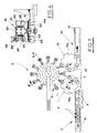
- the machine for filling bottles 1 with a liquid product has means 2 for feeding the said bottles to a carousel 3 which rotates about a vertical axis in the direction indicated by arrow A.
- Feed means 2 consist of a bottle 1 conveying line 4 along which there is an auger 5 which rotates axially in such a manner as to space the conveyed bottles 1 apart.
- Auger 5 is designed to operate in conjunction with a distributor 6, shaped like a star, for example, which rotates in the direction of arrow B.
- the bottles to be fed are held and guided by recesses 6a in distributor 6 and by ring guide 7 which partially surrounds the distributor itself.
- Carousel 3 receives bottles 1 fed by distributor 6 one by one at the point where the equally spaced grippers 8, mounted on the circumference of the carousel itself, are activated. Carousel 3 also mounts dispensing units, labelled 9 in the drawings, which fill the liquid product into bottles 1.
- a full bottle outfeed system 10 consisting of a conveyor line 11 and another distributor 12, shaped like a star, for example, which rotates in the direction of arrow C.
- the outgoing bottles are received by distributor 12 at the point where they are released by grippers 8 and are held and guided by recesses 12a in the distributor and by a ring guide 13 which partially surrounds the distributor.
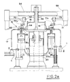
- Dispensing units 9 consist of a plurality of cylinder and plunger assemblies mounted by carousel 3 which lines them up with grippers 8. Each of the said cylinder and plunger assemblies 14 is connected through a valve 15 to a liquid feed chamber 16 and to a filling nozzle 17 alternately. Chamber 16 is mounted on a platform 18 attached to the rotating part of carousel 3.
- Platform 18 is secured to the top of a vertical shaft 19, rotated continuously by the drive motor of the machine through transmission means 20 located at the bottom of the said shaft where the lower face 21 of the carousel frame is situated.
- Shaft 19 is set inside a tubular casing 22 which rotates with it.
- casing 22 is covered by a cylindrical sleeve 18a formed under platform 18.
- the base of sleeve 18a is surrounded by a trap 23 which collects the washing liquid of cylinder and plunger assemblies 14 to which it is connected via tubes 23a.
- tubular element 24 Between shaft 19 and casing 22 and coaxial to them there is a tubular element 24, with appropriate rotational means, about which shaft 19 and casing 22 rotate.
- the bottom end of tubular element 24 is attached to a plate 25 supported by columns 26 which pass through plate 21 and are fixed to plate 27.
- Plate 21 is adjustably mounted for height in relation to plate 27 according to the size of the bottles to be filled.
- Grippers 8 and cylinder and plunger assemblies 14 are driven synchronously by drive means 28 which form a set of vertical columns arranged around the circumference of carousel 3.
- Each of the said drive means consists of a first sleeve 29 the top of which mounts casing 30 of grippers 8 and which is axially crossed by a stem 31.
- the first sleeve 29 is in turn located inside a second sleeve 32 at the top of which there is a crosswise fitting 32a attached to stem 33a of plunger 33 of cylinder and plunger assembly 14.
- Second sleeve 32 is guided by a bushing 34 mounted on the circumference of a plate 35 attached to tubular casing 22.
- First sleeve 29 mounts on its bottom end a roller 36 which rotates about a radial axis in relation to the carousel, the said roller engaging a cam 37 made on a cylindrical wall 38 mounted on lower plate 21 and concentric with the axis of the carousel.
- the bottom end of stem 31 mounts a lever 39 with a roller 40 that rotates about a vertical axis.
- Roller 40 engages a ring cam 41 formed on lower plate 21, as shown in Fig.3.
- grippers 8 consist of a pair of jaws 8a and 8b which rotate on casing 30 by means of pins 42a and 42b respectively. Jaws 8a and 8b are attached to toothed gears 43a and 43b which mesh with each other. Pin 42a has inserted in it a fork 44 which engages a pin 45 vertically attached to stem 31. The rotation of stem 31 through a defined angle, by action of cam 41, thus determines the rotation of the gear pair formed by toothed gears 43a and 43b in such a way as to cause jaws 8a and 8b to move symmetrically from the gripping position P to the release position R and vice versa.
- the bottom end of the aforesaid second sleeve 32 mounts a roller 46 which rotates diametrically in relation to the carousel.
- Roller 46 runs in a groove 47 defined by a ring 48 around tubular casing 22.
- One side of ring 48 is hinged at the bottom to a pivot 49 whose axis is horizontally tangent to a circle concentric with the axis of the carousel.
- Pivot 49 is mounted on a support 50 fixed to a ring shaped disc supported horizontally by columns 52 standing on lower plate 21.
- ring 48 is pivotally attached to stem 53a of an actuator 53. The said actuator is supported in vertical position by disc 51.
- Chamber 16 concentric with the axis of carousel 3, is fed through a tube 54 connected to a tank outside the machine.
- Tube 54 is located above chamber 16, diametrically with respect to carousel 3, and is supported by a frame 55 attached to the fixed structure of carousel 3.
- Tube 54 is connected to a mouthpiece 56 leading out of chamber 16 in accordance with the axis of rotation of the carousel.
- valve 15 consists of a lower casing 57 fixed to carousel platform 18 and an upper casing 58 which rotates on a pin 59 about the vertical axis of valve 15 itself and in relation to lower casing 57.
- Upper casing 58 has a cap 60 held by pin 59 and pushed axially by a spring 61 which presses down on casing 58.
- Lower casing 57 is crossed by a pair of parallel, vertical holes 62 and 63, which, at their bottom ends, are connected with a pair of ducts, respectively 64 and 65, made in platform 18.
- Duct 64 leads out of chamber 16, whilst duct 65 is connected to dispensing nozzle 17.
- Platform 18 is also crossed by a vertical hole 66, whose bottom end is connected to cylinder and plunger assembly 14 and whose top end extends into lower casing 57 of the valve.
- the axes of holes 62, 63 and 66 are distributed around a circle concentric with the axis of rotation of upper valve casing 58.
- Upper, rotating casing 58 is crossed by an approximately semicircular channel 67 in a horizontal plane. At each end and in the middle of channel 67 there are downward opening holes 67a, 67b and 67c which serve to connect hole 66 to ducts 64 and 65 alternately, in accordance with the angular position assumed by rotating valve casing 58.
- Cap 60 of rotating casing 58 has on its top an eccentric pin 68 which rotates axially and held by a sprung bolt 69.
- Pin 68 is designed to intercept a pair of cams 70 and 71, respectively first and second cam, during the rotation of carousel 3, the said cams being carried by fixed frame 55 of the carousel in diametrically opposite positions in relation to the axis of the carousel itself.
- Cams 70 and 71 have a chamfered face designed to act as a sliding guide for pin 68.
- Cams 70 and 71 are supported by actuators 72 and 73 respectively driven in a vertical direction in such a manner that they can be lifted to positions 70a and 71a in which they are disengaged from pins 68. The raising of cams 70 and 71 make it possible for washing cycles to be performed on the machine.
- bottle 1 After being gripped by jaws 8a and 8b, bottle 1 is lifted vertically, as shown by arrow D in Fig.6a, in such a way that nozzle 17 of dispensing unit 9 is inserted into the mouth of bottle 1.
- the raising of the bottle is achieved by the axial sliding of the first sleeve 29, attached to casing 30 of grippers 8.
- the said sliding motion is controlled by cam 37 in which roller 36 carried by sleeve 29 slides.
- channel 67 of upper casing 58 of valve 15 is connected through holes 67a and 67c to duct 64 and to hole 66 leading into cylinder and plunger assembly 14.
- the said cylinder and plunger assembly 14 is thus connected to feed chamber 16 and liquid is sucked into the cylinder when plunger 33 is driven downwards in the direction of arrow E shown in Fig. 6a.
- valve 15 switches the connection of cylinder and plunger assembly 14 from liquid suction duct 64 to duct 65 which conveys the liquid to nozzle 17.
- eccentric pin 68 of the valve is intercepted by cam 70, thus causing upper casing 58 of the valve to rotate in relation to lower, fixed casing 57.
- channel 67 of casing 58 is connected through holes 67a and 67b to hole 66 and to duct 65, thus enabling the liquid to flow out through the nozzle.
- plunger 33 of cylinder and plunger assembly 14 is achieved by the axial sliding of second sleeve 32, attached to stem 33a of the plunger. This sliding motion is effected by roller 46, mounted by sleeve 32, which runs in the circumferential groove of ring 48.
- the stroke of plunger 33 may be adjusted by varying the angle of ring 48, usually set in an oblique plane in relation to carousel 3. To adjust the stroke, the ring may be shifted using actuator 53, to the side opposite its pivot 49, as shown schematically by dashed line 74 in Fig.2b. Adjusting the stroke of the plunger makes it possible to vary the amount of liquid to be filled into the bottles.
- bottle 1 is gradually lowered, as shown by arrow G in Fig.6b, through the sliding of first sleeve 29 controlled by cam 37.
- cam 41 causes jaws 8a and 8b to open at release position R in such a way that distributor 12 of outfeed system 10 can engage the bottle and move it away.
- the work cycle described above is carried out by all the dispensing units mounted on the circumference of carousel 3.
- the machine described thus makes it possible to synchronize the driving of cylinder and plunger assembly 14, the opening and closing of bottle grippers 8 and the vertical movement of the said grippers 8, in such a way as to work in conjunction with nozzle 17 of liquid dispensing units 9.
- the device therefore occupies very little space and allows easy access to the internal parts of the carousel.
- the supply of liquid to dispensing units 9 is effected by a single valve for each dispensing nozzle 17.
- the said valves are rotated by carousel 3 and are fed by a chamber mounted on the same axis as carousel 3 itself.
- the space occupied by the valves is thus very limited, making for a very practical set-up.
- the machine may be adjusted in accordance with the size of the bottles to be filled, as shown in Fig. 7, which shows carousel 3 set for filling bottles of the largest size.
- Such adjustment is effected by moving plate 21 upwards away from plate 27 in such a manner as to also raise drive means 28, which are attached to plate 21, and thus vary the distance between grippers 8 and the feed level of bottles 1, the said level being defined by rotary distributor 6 (position X in Figures 2b and 7).
- Figures 8a and 8b show carousel when cylinder and plunger assemblies 14 are being washed.
- ring 48 is moved to a horizontal position (position Y, Fig. 8b), by rotating it about its pivot 49 by means of actuator 53.
- roller 46 which runs in groove 47 of ring 48, is not moved in vertical direction and the reciprocating motion of plunger 33 of cylinder and plunger assemblies 14 is stopped.
- Column 19 is lowered by means of elements 80 (Fig.8b).
- plunger 33 stops in the raised position Z (Fig. 8a) where the inside diameter of the cylindrical lining of cylinder and plunger assembly 14 is larger and does not form a hydraulic seal.
- cams 70 and 71 are moved to raised positions 70a and 71a through their respective actuators 72 and 73, so as to interrupt drive to valves 15. Valves 15 are stopped in the position where chamber 16 is connected to cylinder and plunger assemblies 14.
- cylinder and plunger assemblies 14 may be filled with an appropriate washing liquid .
- the washing liquid flows to the bottom of cylinder and plunger assemblies 14 and collects in trap 23.
Landscapes
- Filling Of Jars Or Cans And Processes For Cleaning And Sealing Jars (AREA)
- Basic Packing Technique (AREA)
- Supply Of Fluid Materials To The Packaging Location (AREA)
Claims (10)
- Verfahren zur Füllung von Behältern mit flüssigen Produkten, das folgende Schritte beinhaltet:
Aufnehmen der zu füllenden Behälter (1) durch Haltevorrichtungen, die an einem Karussell (3) befestigt sind, das sich um eine senkrechte Achse dreht und das die von Zuführvorrichtungen (2) kommenden Behälter (1) entgegennimmt;
senkrechtes Anheben der genannten Behälter (1) zusammen mit den genannten Haltevorrichtungen, so daß die Düsen (17) von Flüssigkeitsspendern (9), die oberhalb der Haltevorrichtungen auf dem genannten Karussell (3) angebracht sind, in die Öffnungen der Behälter eingeführt werden;
Abgabe der Flüssigkeit in die genannten Behälter (1) durch die genannten Düsen (17);
langsames Absenken der Behälter;
Loslassen der gefüllten Behälter (1) und Übergabe an ein Auslaufsystem (10);
das genannte Verfahren ist dadurch gekennzeichnet, daß es folgende Schritte beinhaltet:
das Halten der genannten Behälter durch Greifer (8);
das Drehen eines Stabes (31) um seine Längsachse, wobei die genannte Axialdrehung durch einen Nocken (41) bewirkt wird, der in Form eines Ringes auf einer waagerechten Platte (21) ausgeführt ist und eine Rolle (40) steuert, die am unteren Ende des genannten Stabes (31) montiert ist; der genannte Stab ist so mit den Haltevorrichtungen verbunden, daß die Behälter aufgenommen werden;
das Anheben einer ersten Manschette (29), die den Stab (31) umhüllt und mit den genannten Greifern verbunden ist, wobei das Anheben durch einen Nocken (37) bewirkt wird, welcher auf einer zylinderförmigen, zur Achse des genannten Karussells (3) konzentrischen Wand (38) ausgeführt ist und der eine Rolle (36) betätigt, die am unteren Ende der genannten Manschette (29) montiert ist, so daß die Behälter angehoben werden;
das Absenken der genannten ersten Manschette (29), wobei das Absenken durch den genannten Nocken (37) bewirkt wird, welcher auf der genannten zylinderförmigen Wand (38) ausgeführt ist, sowie das gleichzeitige Betätigen der genannten Spendevorrichtungen (9) durch eine zweite Manschette (32), welche die erste Manschette (29) umhüllt und mit dem Kolben (33) einer Zylinder-Kolben-Gruppe (14) einer der genannten Spendevorrichtungen (9) verbunden sowie mit einer Rolle (46) versehen ist, die in einer Rille (47) läuft, welche entlang des Umfangs eines Ringes (48) ausgeführt ist, der die Drehachse des Karussells (3) umschreibt und in schräger Ebene zum Karussell (3) angeordnet ist, so daß die genannten Behälter langsam abgesenkt werden, während die Flüssigkeit durch die genannten Düsen (17) eingefüllt wird;
das Drehen des genannten Stabes (31) um seine Längsachse durch den genannten Nocken (41), der auf der genannten waagerechten Platte (21) ausgeführt ist, so daß die bereits gefüllten Behälter (1) losgelassen werden. - Maschine zum Füllen von Behältern mit flüssigen Produkten, bestehend aus einer Zuführvorrichtung (2) für die zu füllenden Behälter (1); einem Karussell (3), das sich um eine senkrechte Achse dreht und die von der Zuführvorrichtung (2) kommenden Behälter (1) einzeln aufnimmt; Flüssigkeitsspender (9), die ebenfalls außen um das Karussell (3) herum montiert sind; sowie eine Auslaufeinheit (10) um die gefüllten Behälter von dem Karussell (3) wegzubefördern;
Haltevorrichtungen zum Festhalten der Behälter (1);
Vorrichtung (28) zum synchronen Antrieb der Haltevorrichtungen und der genannten Spendevorrichtungen (9), wobei die genannte Vorrichtung (28) so ausgelegt ist, daß sie die genannten Haltevorrichtungen abwechselnd zwischen einer unteren Position, in der die Behälter (1) aufgenommen und losgelassen werden, und einer oberen Position, in der die Düsen (17) der genannten Spendevorrichtungen (9) in die Behälteröffnungen eingeführt sind, auf und ab bewegt;
eine Kammer (16) für die Zufuhr des flüssigen Produkts, die konzentrisch auf eine Plattform (18) des Karussells (3) montiert ist;
mehrere Leitungen (64,65), die in der Plattform (18) ausgeführt sind und dazu dienen, die Kammer (16) mit den genannten Spendevorrichtungen (9) zu verbinden;
mehrere Ventile (15), die entlang des Umfangs der Plattform (18) angebracht sind, wobei jedes Ventil mit jeweils einer der genannten Spendevorrichtungen (9) verbunden und so ausgelegt ist, daß es in einer Weise betätigt wird, daß das flüssige Produkt durch die genannten Leitungen (64,65) den genannten Spendevorrichtungen (9) zugeführt werden kann;
die genannte Maschine ist dadurch gekennzeichnet, daß die genannten Haltevorrichtungen Greifer (8) mit Backen sind, wobei sich die genannten Backen im Einlaufbereich der genannten Behälter (1) zu einer Greifposition (P) schließen und im Auslaufbereich der Behälter (1) zu einer Freigabeposition (R) öffnen; und ist weiter dadurch gekennzeichnet, daß die Vorrichtung (28) zum synchronen Antrieb der Greifer (8) und der Spendevorrichtungen (9) folgendes umfaßt:
eine erste Manschette (29), auf der oben das Gehäuse (30) der Greifer (8) und unten eine Rolle (36) angebracht ist, die in einen Nocken (37) eingreift, welcher auf einer zylinderförmigen, zur Achse des genannten Karussells (3) konzentrischen Wand (38) ausgeführt ist;
eine zweite Manschette (32), in der die mit ihr konzentrische erste Manschette (29) verläuft, wobei die zweite Manschette (32) mit dem Kolben (33) einer Zylinder-Kolben-Gruppe (14) einer der genannten Spendevorrichtungen (9) verbunden und mit einer Rolle (46) versehen ist, die sich entsprechend einer diametrischen Achse im Verhältnis zum Karussell (3) drehen kann. Die Rolle (46) läuft in einer Rille (47), die durch den Umfang eines Ringes (48) gebildet wird, der die Drehachse des Karussells (3) umringt und in schräger Ebene zum Karussell (3) angeordnet ist;
einen durch die genannte erste Manschette (29) geführten Stab (31), der unten mit einer Rolle (40) versehen ist, die sich um eine senkrechte Achse drehen kann und in einen Nocken (41) in Form eines Ringes auf einer waagerechten Platte (21) eingreift, während das obere Ende des Stabes (31) so ausgeführt ist, daß es ein Zahnradpaar (43a,43b) in einem festgelegten Winkel dreht, welches die Bewegung auf die genannten Greifer (8) überträgt, wodurch das Backenpaar (8a,8b) von einer Greifposition (P), in der die Behälter (1) festgehalten werden, in eine Freigabeposition (R) gedreht wird, in der die Behälter losgelassen werden. - Maschine gemäß Anspruch 2, dadurch gekennzeichnet,
daß die genannten Backen (8a,8b) drehbar auf dem genannten Gehäuse (30) der Greifer (8) montiert sind und daß an ihnen zwei ineinandergreifende Zahnräder (43a,43b) angebracht sind, die zusammen ein Getriebepaar bilden; und daß eines der Zahnräder in seiner Mitte eine Gabel (44) aufweist, in die ein senkrecht an dem Stab (31) angebrachter Bolzen (45) eingreift. - Maschine gemäß Anspruch 2, dadurch gekennzeichnet,
daß eine Seite des genannten Ringes (48) an der Unterseite drehbar in einen Zapfen (49) eingehängt ist, dessen Achse horizontal tangential zu einem zur Karussellachse (3) konzentrischen Kreis ist. Die diametrisch gegenüberliegende Seite des genannten Ringes (48) ist drehbar mit einem Antrieb (53) mit senkrechter Achse verbunden. - Maschine gemäß Anspruch 2, dadurch gekennzeichnet,
daß jedes der genannten Ventile (15) aus einem an der Plattform (18) des Karussells (3) befestigten unteren Gehäuse (57) und einem oberen Gehäuse (56) besteht, das sich gegenüber dem unteren Gehäuse (57) um die Vertikalachse des Ventils (15) dreht, und daß durch das obere Gehäuse (58) ein Kanal (67) führt, der abwechselnd mit den genannten Leitungen (64,65) verbunden werden kann. - Maschine gemäß Anspruch 5, dadurch gekennzeichnet,
daß der genannte Kanal (67) bogenförmig ist und fast einen Halbkreis auf einer horizontalen Ebene beschreibt; an den beiden Enden und in der Mitte dieses Kanals (67) sind nach unten weisende Öffnungen (67a,67b,67c) ausgeführt, die dazu dienen, eine durch das Karussell (3) gedrehte Zylinder-Kolben-Gruppe (14) abwechselnd mit den Leitungen (64,65) zu verbinden, so daß das flüssige Produkt aus der genannten Kammer (16) angesaugt werden und anschließend in die Spendedüse (17) fließen kann. - Maschine gemäß Anspruch 5, dadurch gekennzeichnet,
daß sich oben auf dem oberen Gehäuse (58) ein Exzenterstift (69) befindet, der axial drehbar und so ausgeführt ist, daß er während der Drehung des Karussells (3) in ein Paar Nocken (70,71) (erster bzw. zweiter Nocken) eingreift, wobei die Nocken auf einem festen Rahmen (55) des Karussells angebracht sind, und zwar im Verhältnis zum Karussell (3) in diametral gegenüberliegenden Positionen. - Maschine gemäß Anspruch 7, dadurch gekennzeichnet,
daß die genannten Nocken (70,71) jeweils von Stellgliedern (72,73) getragen werden, die in vertikaler Richtung so angetrieben werden, daß sie in die Positionen (70a,71a) gehoben und somit von den Exzenterstiften (68) der Ventile (15) getrennt werden können, so daß die Ventile (15) in der Position angehalten werden, in der die Kammer (16) mit den Zylinder-Kolben-Gruppen (14) verbunden ist. - Maschine gemäß Anspruch 2, in der die zylindrische Ummantelung der genannten Zylinder-Kolben-Gruppe so an dem Karussell (3) befestigt ist, daß sie im rechten Winkel zur Karussellachse steht, wobei die genannte Maschine dadurch gekennzeichnet ist, daß die genannten Ummantelungen an ihrem oberen Ende einen größeren Durchmesser als an ihrem unteren Ende aufweisen, so daß die genannten oberen Enden keine hydraulische Abdichtung mit den entsprechenden Kolben (33) bilden; daß die Maschine mit einem Wasserverschluß (23) versehen ist, an den jedes Mantelunterteil über ein Rohr (23a) angeschlossen ist; daß die Maschine Vorrichtungen (19,80) umfaßt, die zur Bewegung des genannten Karussells nach unten dienen, so daß, wenn der genannte Ring (48) um seinen Zapfen (49) gedreht wird, bis er quer zur Achse des genannten Karussells (3) steht, jeder Kolben (33) in die oberste Position bewegt werden kann, damit eine Reinigungsflüssigkeit in alle genannten Ummantelungen einfließen, an den Seiten der Ummantelungen herab und in den genannten Wasserverschluß (23) hineinfließen kann.
- Maschine gemäß Anspruch 2, dadurch gekennzeichnet,
daß die genannte Kammer (16) über einen Schlauch (54) versorgt wird, der an einen außerhalb der Maschine, oberhalb der Kammer gegenüber dem Karussell (3) angebrachten Vorratsbehälter angeschlossen ist, wobei der genannte Schlauch (54) von einem festen Rahmen (55) gehalten wird und an ein Mundstück (56) angeschlossen ist, das in Übereinstimmung mit der Drehachse des Karussells (3) aus der Kammer (16) austritt.
Applications Claiming Priority (2)
| Application Number | Priority Date | Filing Date | Title |
|---|---|---|---|
| IT373390 | 1990-11-14 | ||
| IT00373390A IT1242877B (it) | 1990-11-14 | 1990-11-14 | Metodo e macchina per il riempimento di contenitori con sostanze liquide. |
Publications (3)
| Publication Number | Publication Date |
|---|---|
| EP0486438A2 EP0486438A2 (de) | 1992-05-20 |
| EP0486438A3 EP0486438A3 (en) | 1992-08-12 |
| EP0486438B1 true EP0486438B1 (de) | 1995-05-10 |
Family
ID=11111575
Family Applications (1)
| Application Number | Title | Priority Date | Filing Date |
|---|---|---|---|
| EP91830490A Expired - Lifetime EP0486438B1 (de) | 1990-11-14 | 1991-11-12 | Verfahren und Vorrichtung zum Befüllen von Behältern mit Flüssigkeiten |
Country Status (4)
| Country | Link |
|---|---|
| EP (1) | EP0486438B1 (de) |
| DE (1) | DE69109627T2 (de) |
| ES (1) | ES2071968T3 (de) |
| IT (1) | IT1242877B (de) |
Families Citing this family (7)
| Publication number | Priority date | Publication date | Assignee | Title |
|---|---|---|---|---|
| IT1321245B1 (it) * | 2000-05-05 | 2004-01-08 | Ima Spa | Macchina riempitrice per il riempimento di contenitori con sostanzeliquide |
| ITBO20040630A1 (it) * | 2004-10-14 | 2005-01-14 | Marchesini Group Spa | Macchina per il riempimento in continuo di contenitori con prodotti liquidi |
| FR2952036B1 (fr) * | 2009-11-05 | 2012-02-10 | Lb Systems | Dispositif de guidage et d'entrainement de vanne rotative de machine de dosage |
| EP2889260B1 (de) * | 2013-12-30 | 2016-03-09 | Sidel S.p.a. Con Socio Unico | Einheit zur Durchführung einer Operation an einem mit einem gießbaren Produkt befüllbaren Behälter |
| WO2019002601A1 (en) * | 2017-06-30 | 2019-01-03 | Tetra Laval Holdings & Finance S.A. | CAM-CONTROLLED SYSTEM |
| CN108907712B (zh) * | 2018-08-31 | 2023-07-25 | 济南大学 | 一种玻璃瓶生产装配设备 |
| CN116214119B (zh) * | 2023-05-11 | 2023-07-14 | 汕头市铭信实业有限公司 | 基于挤压偏移出料的可调式按咀插管组装机及组装方法 |
Family Cites Families (5)
| Publication number | Priority date | Publication date | Assignee | Title |
|---|---|---|---|---|
| US4108221A (en) * | 1976-08-06 | 1978-08-22 | Gerhart Engineering & Machine Co. | Container filling machine |
| DE3112341A1 (de) * | 1981-03-28 | 1982-10-07 | Seitz-Werke Gmbh, 6550 Bad Kreuznach | "anordnung an flaschenfuellmaschinen" |
| AU554222B2 (en) * | 1981-10-13 | 1986-08-14 | Toyo Garasu K.K. | Inspecting glass containers |
| IT1214901B (it) * | 1985-11-11 | 1990-01-31 | Simonazzi Spa A & L | Riempitrice rotativa continua equipaggiata,per il sollevamento meccanico delle bottiglie vuote eper l'abbassamento libero delle bottiglie riempite,soltanto con con punterie prensili munite di chiavistello di bloccaggio sincronizzato col processo diriempimento |
| DE3903768C2 (de) * | 1988-08-20 | 1995-07-20 | Khs Masch & Anlagenbau Ag | Verfahren zum Füllen von Behältern, insbesondere Flaschen, mit einem vorzugsweise unter Umgebungsdruck stehenden flüssigen Füllgut sowie Füllmaschine zum Durchführen dieses Verfahrens |
-
1990
- 1990-11-14 IT IT00373390A patent/IT1242877B/it active IP Right Grant
-
1991
- 1991-11-12 EP EP91830490A patent/EP0486438B1/de not_active Expired - Lifetime
- 1991-11-12 ES ES91830490T patent/ES2071968T3/es not_active Expired - Lifetime
- 1991-11-12 DE DE69109627T patent/DE69109627T2/de not_active Expired - Fee Related
Also Published As
| Publication number | Publication date |
|---|---|
| ES2071968T3 (es) | 1995-07-01 |
| DE69109627D1 (de) | 1995-06-14 |
| EP0486438A3 (en) | 1992-08-12 |
| DE69109627T2 (de) | 1996-02-08 |
| IT1242877B (it) | 1994-05-18 |
| EP0486438A2 (de) | 1992-05-20 |
| IT9003733A1 (it) | 1992-05-14 |
| IT9003733A0 (it) | 1990-11-14 |
Similar Documents
| Publication | Publication Date | Title |
|---|---|---|
| EP0486439B1 (de) | Anordnung zum synchronen Antrieb von Einrichtungen zur Füllung und Containerbehandlung in Getränkeabfüllern | |
| US7114535B2 (en) | Circular motion filling machine and method | |
| RU2369556C2 (ru) | Устройство для смены деталей, установленных на вращающихся машинах для обработки емкостей | |
| US8333052B2 (en) | Machine for filling capsules with pharmaceutical products | |
| US3837378A (en) | Device for the transport and filling of ampoules | |
| US4108221A (en) | Container filling machine | |
| US4051878A (en) | Rotary filler apparatus | |
| MXPA04010980A (es) | Sistema para el llenado y cerrado de cartuchos que contienen fluido. | |
| EP0486438A2 (de) | Verfahren und Vorrichtung zum Befüllen von Behältern mit Flüssigkeiten | |
| JP2001278388A (ja) | ロータリー式連続充填装置 | |
| US5158168A (en) | Container transfer device | |
| EP0486440B1 (de) | Vorrichtung zum Ausgeben von flüssigen Produkten zu drehbeweglichen Teilen, insbesondere für Getränkeabfüller | |
| CA1315751C (en) | Apparatus for minimizing foam in filling containers | |
| US2749688A (en) | Automatic filling and sealing machine for ampuls or other small containers | |
| US2353519A (en) | Mechanism for charging containers | |
| US3405500A (en) | Method and apparatus for filling liquids into bottles and for capping the same | |
| US8359815B2 (en) | Machine for filling capsules with pharmaceutical products | |
| JP3897394B2 (ja) | 不定形容器充填装置 | |
| US3105525A (en) | Machine and method for filling containers | |
| US1958769A (en) | Machine for crimping plastic caps on bottles | |
| US4171933A (en) | Pumping mechanism | |
| JP2011011048A (ja) | カプセルに製薬製品を充填する機械 | |
| JPH0912093A (ja) | ピストン式定量充填機の洗浄装置 | |
| EP0074418A1 (de) | Flüssigkeits-Ausgabevorrichtung | |
| JPS5940717B2 (ja) | ガス充填打栓装置 |
Legal Events
| Date | Code | Title | Description |
|---|---|---|---|
| PUAI | Public reference made under article 153(3) epc to a published international application that has entered the european phase |
Free format text: ORIGINAL CODE: 0009012 |
|
| AK | Designated contracting states |
Kind code of ref document: A2 Designated state(s): CH DE ES FR GB LI |
|
| PUAL | Search report despatched |
Free format text: ORIGINAL CODE: 0009013 |
|
| AK | Designated contracting states |
Kind code of ref document: A3 Designated state(s): CH DE ES FR GB LI |
|
| 17P | Request for examination filed |
Effective date: 19921030 |
|
| 17Q | First examination report despatched |
Effective date: 19930604 |
|
| GRAA | (expected) grant |
Free format text: ORIGINAL CODE: 0009210 |
|
| AK | Designated contracting states |
Kind code of ref document: B1 Designated state(s): CH DE ES FR GB LI |
|
| PG25 | Lapsed in a contracting state [announced via postgrant information from national office to epo] |
Ref country code: LI Effective date: 19950510 Ref country code: CH Effective date: 19950510 |
|
| REF | Corresponds to: |
Ref document number: 69109627 Country of ref document: DE Date of ref document: 19950614 |
|
| ET | Fr: translation filed | ||
| REG | Reference to a national code |
Ref country code: ES Ref legal event code: FG2A Ref document number: 2071968 Country of ref document: ES Kind code of ref document: T3 |
|
| REG | Reference to a national code |
Ref country code: CH Ref legal event code: PL |
|
| PLBE | No opposition filed within time limit |
Free format text: ORIGINAL CODE: 0009261 |
|
| STAA | Information on the status of an ep patent application or granted ep patent |
Free format text: STATUS: NO OPPOSITION FILED WITHIN TIME LIMIT |
|
| 26N | No opposition filed | ||
| REG | Reference to a national code |
Ref country code: GB Ref legal event code: IF02 |
|
| PGFP | Annual fee paid to national office [announced via postgrant information from national office to epo] |
Ref country code: DE Payment date: 20081128 Year of fee payment: 18 |
|
| PGFP | Annual fee paid to national office [announced via postgrant information from national office to epo] |
Ref country code: FR Payment date: 20081118 Year of fee payment: 18 Ref country code: ES Payment date: 20081127 Year of fee payment: 18 |
|
| PGFP | Annual fee paid to national office [announced via postgrant information from national office to epo] |
Ref country code: GB Payment date: 20081127 Year of fee payment: 18 |
|
| GBPC | Gb: european patent ceased through non-payment of renewal fee |
Effective date: 20091112 |
|
| REG | Reference to a national code |
Ref country code: FR Ref legal event code: ST Effective date: 20100730 |
|
| PG25 | Lapsed in a contracting state [announced via postgrant information from national office to epo] |
Ref country code: FR Free format text: LAPSE BECAUSE OF NON-PAYMENT OF DUE FEES Effective date: 20091130 |
|
| PG25 | Lapsed in a contracting state [announced via postgrant information from national office to epo] |
Ref country code: DE Free format text: LAPSE BECAUSE OF NON-PAYMENT OF DUE FEES Effective date: 20100601 |
|
| PG25 | Lapsed in a contracting state [announced via postgrant information from national office to epo] |
Ref country code: GB Free format text: LAPSE BECAUSE OF NON-PAYMENT OF DUE FEES Effective date: 20091112 |
|
| REG | Reference to a national code |
Ref country code: ES Ref legal event code: FD2A Effective date: 20110307 |
|
| PG25 | Lapsed in a contracting state [announced via postgrant information from national office to epo] |
Ref country code: ES Free format text: LAPSE BECAUSE OF NON-PAYMENT OF DUE FEES Effective date: 20110304 |
|
| PG25 | Lapsed in a contracting state [announced via postgrant information from national office to epo] |
Ref country code: ES Free format text: LAPSE BECAUSE OF NON-PAYMENT OF DUE FEES Effective date: 20091113 |