EP0486459A1 - Fixation d'outil pour récolteuses-hacheuses - Google Patents
Fixation d'outil pour récolteuses-hacheuses Download PDFInfo
- Publication number
- EP0486459A1 EP0486459A1 EP91890252A EP91890252A EP0486459A1 EP 0486459 A1 EP0486459 A1 EP 0486459A1 EP 91890252 A EP91890252 A EP 91890252A EP 91890252 A EP91890252 A EP 91890252A EP 0486459 A1 EP0486459 A1 EP 0486459A1
- Authority
- EP
- European Patent Office
- Prior art keywords
- bolts
- tool carrier
- tool
- elongated holes
- tabs
- Prior art date
- Legal status (The legal status is an assumption and is not a legal conclusion. Google has not performed a legal analysis and makes no representation as to the accuracy of the status listed.)
- Granted
Links
- 241001124569 Lycaenidae Species 0.000 title 1
- 239000004459 forage Substances 0.000 title 1
- 238000006073 displacement reaction Methods 0.000 claims abstract description 8
- 230000015572 biosynthetic process Effects 0.000 claims description 3
- 230000007423 decrease Effects 0.000 claims description 2
- 230000008602 contraction Effects 0.000 abstract 1
- 230000014759 maintenance of location Effects 0.000 abstract 1
- 238000010276 construction Methods 0.000 description 2
- 230000000694 effects Effects 0.000 description 2
- 239000000463 material Substances 0.000 description 2
- 230000005540 biological transmission Effects 0.000 description 1
- 238000013016 damping Methods 0.000 description 1
- 238000010586 diagram Methods 0.000 description 1
- 238000003780 insertion Methods 0.000 description 1
- 230000037431 insertion Effects 0.000 description 1
- 230000002787 reinforcement Effects 0.000 description 1
- 239000004575 stone Substances 0.000 description 1
Images

Classifications
-
- A—HUMAN NECESSITIES
- A01—AGRICULTURE; FORESTRY; ANIMAL HUSBANDRY; HUNTING; TRAPPING; FISHING
- A01D—HARVESTING; MOWING
- A01D34/00—Mowers; Mowing apparatus of harvesters
- A01D34/01—Mowers; Mowing apparatus of harvesters characterised by features relating to the type of cutting apparatus
- A01D34/412—Mowers; Mowing apparatus of harvesters characterised by features relating to the type of cutting apparatus having rotating cutters
- A01D34/63—Mowers; Mowing apparatus of harvesters characterised by features relating to the type of cutting apparatus having rotating cutters having cutters rotating about a vertical axis
- A01D34/73—Cutting apparatus
- A01D34/733—Cutting-blade mounting means
-
- A—HUMAN NECESSITIES
- A01—AGRICULTURE; FORESTRY; ANIMAL HUSBANDRY; HUNTING; TRAPPING; FISHING
- A01D—HARVESTING; MOWING
- A01D34/00—Mowers; Mowing apparatus of harvesters
- A01D34/01—Mowers; Mowing apparatus of harvesters characterised by features relating to the type of cutting apparatus
- A01D34/412—Mowers; Mowing apparatus of harvesters characterised by features relating to the type of cutting apparatus having rotating cutters
- A01D34/63—Mowers; Mowing apparatus of harvesters characterised by features relating to the type of cutting apparatus having rotating cutters having cutters rotating about a vertical axis
- A01D34/73—Cutting apparatus
- A01D34/736—Flail type
Definitions
- the invention relates to a tool holder for mowing or chopping machines with a rotating tool carrier, on which the tools are pivotally fastened about bolts parallel to the axis of rotation of the tool carrier, the ends of each of the bolts carrying at least one tool being oriented in elongated holes radially to the axis of rotation of two opposite, attached to the tool carrier and loosely protruding from this tabs or forming the tool carrier itself disks loosely and secured in the radially outer portion of the elongated holes against axial displacement.
- the bolts can of course move in the elongated holes, i.e. under the effect of the centrifugal force of the tools, they naturally take the position at the radially outer end of the elongated holes, where they are secured against axial displacement and therefore cannot emerge from the elongated holes.
- they or the tools need only be moved to the radially inner end of the elongated holes when the tool carrier is stationary, where there is no security against axial displacement and the bolts can therefore be ejected. The removal or insertion of the tools can therefore be carried out easily without an auxiliary device.
- Such a tool holder is known (EP-A1 0 395 624) and has already proven itself.
- this elongated hole section is covered by sheets welded to the brackets or to the disks forming the tool carrier. This not only increases the cost of materials, but also brings about an undesirable increase in dimensions in the axial direction of the bolt in many cases.
- the tabs or disks must be made relatively thick in order to ensure that the bolt ends have a sufficiently deep engagement in the elongated holes.
- leaf springs are fastened on the underside of the cutting plate, which also have a keyhole-shaped recess for holding a pivot pin for the knife, the pivot pin being inserted at the wider part of the recess and then being displaced towards the narrower part where the hole edges engage in a pinch constriction and hold it in place.
- a separate plate is used, which is riveted to the leaf spring, so that a bolt change is difficult.
- the knife is simply placed on the bolt and axial displacement of the knife on the bolt is prevented by the fact that the leaf spring presses the knife against the cutting plate from below. Apart from the fact that considerable technical effort is required here, a tool change cannot take place without a tool, since the leaf spring must be pushed away from the cutting plate in order to be able to remove or replace the knife.
- the invention is therefore based on the object of improving the tool holder described at the outset in such a way that, without impairing the ease of use, full security against loosening of the tools is ensured even with extremely thin tabs or disks, and material savings can also be achieved.
- the invention achieves the stated object in that the two opposing elongated holes are narrowed in a manner known per se in the radially outer section, the bolt ends having a diameter adapted to the full elongated hole width, and in that the narrowing is only achieved by the sides facing the other elongated hole provided projections of the elongated side walls are narrowed and the bolts have corresponding constrictions.
- the bolt end then forms a head, so to speak, which is undercut by the projection of the elongated side walls, so that the bolt, since both ends and both elongated holes are of the same design, holds the tabs or disks together like a rivet and, of course, also fully against axial displacement itself is secured without needing any cover.
- the constriction is missing in the radially inner elongated hole area, so that the bolt can be inserted or ejected easily and without tools as before.
- the advantage of the construction according to the invention also lies in the fact that the bolt ends do not need to protrude beyond the surfaces of the tabs or disks and that the tabs or disks can be made very thin, since they are held together by the bolts and their gaping apart is therefore impossible.
- a particularly expedient construction results if the opposing elongated holes for the formation of a projection have, in a manner known per se, hollow-conical or oblique flanks and the bolts are flared at both ends.
- the bolts have a cylindrical basic shape with recesses for the engagement of the elongated hole projections, in which case the bolt diameter in the area of the tool eyes need not be reduced. It goes without saying that two or more tools in the form of knives, wind blades or the like are also on the bolt. can be stored.
- the distance between the mutually opposite tabs or disks to the radially inner end of the elongated hole increases or decreases and the tabs or disks are designed to spring towards or away from one another. Since the bolt in each case has the constrictions of the ends of the elongated holes, the radially inwardly increasing tab or disc spacing prevents it from moving inwards to the position where it could come loose. If the bolt has recesses for the engagement of the elongated hole projections, the reduction in the tab or disc spacing towards the radially inner elongated hole end has the same effect. An additional protection against a bolt solution is thus achieved. When you want to assemble or disassemble the bolts, the two brackets or washers must of course be pressed together or bent apart.
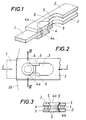
- the tool for example a knife 1 is held between two mutually opposite tabs 2, which are fastened to a rotating (not shown) tool carrier, projecting approximately radially.
- disks 2a can also be provided, which themselves form the tool carrier (indicated by dash-dotted lines in FIG. 2).
- the mutually opposite tabs 2 or disks 2a have slots 3 directed radially to the axis of rotation, which receive the ends of a bolt 4 parallel to the axis of rotation of the tool carrier, on which the knives 1 are pivotably mounted.
- the elongated holes 3 In the radially outer section, the elongated holes 3 have a projection 5 constricting them on their side facing the respective other elongated hole, and the bolt 3 is constricted accordingly.
- the opposing elongated holes 3 have hollow-conical or oblique flanks for the formation of the projection, and the bolt 4 is flared at both ends 4a.
- the projections 5 are of course missing in the radially inner section, so that there the bolt 4 can be released from the elongated holes 3. 4 and 5, the bolt 4 has a cylindrical basic shape and has recesses 4b for the engagement of the elongated hole projections 5.
- Fig. 6 shows elongated holes 3, which are expanded approximately heart-shaped in their radially outer section 3a, but this extension naturally has dimensions such that the bolt 4 cannot pass through due to the projections 5.
- the extension 3a allows the bolt to roll a little on one or the other oblique boundary surface of the extension in the event of a stronger blow to the knife 1 and thereby achieve damping or reduce the transmission of the blow to the tool carrier.
Landscapes
- Life Sciences & Earth Sciences (AREA)
- Environmental Sciences (AREA)
- Harvester Elements (AREA)
Applications Claiming Priority (2)
| Application Number | Priority Date | Filing Date | Title |
|---|---|---|---|
| AT2318/90 | 1990-11-16 | ||
| AT0231890A AT397172B (de) | 1990-11-16 | 1990-11-16 | Werkzeughalterung für mäh- bzw. häckselmaschinen |
Publications (2)
| Publication Number | Publication Date |
|---|---|
| EP0486459A1 true EP0486459A1 (fr) | 1992-05-20 |
| EP0486459B1 EP0486459B1 (fr) | 1994-06-15 |
Family
ID=3532152
Family Applications (1)
| Application Number | Title | Priority Date | Filing Date |
|---|---|---|---|
| EP91890252A Expired - Lifetime EP0486459B1 (fr) | 1990-11-16 | 1991-10-23 | Fixation d'outil pour récolteuses-hacheuses |
Country Status (5)
| Country | Link |
|---|---|
| US (1) | US5175985A (fr) |
| EP (1) | EP0486459B1 (fr) |
| AT (1) | AT397172B (fr) |
| CA (1) | CA2055527A1 (fr) |
| DE (1) | DE59101942D1 (fr) |
Cited By (4)
| Publication number | Priority date | Publication date | Assignee | Title |
|---|---|---|---|---|
| DE19536704A1 (de) * | 1995-09-30 | 1997-04-03 | Humbert Manfred Dipl Ing Fh | Zweiteiliges Hackermesser |
| EP2198686A1 (fr) * | 2008-12-19 | 2010-06-23 | Andreas Stihl AG & Co. KG | Appareil de travail |
| EP2433484A4 (fr) * | 2009-05-19 | 2013-08-07 | Chikusui Canycom Co Ltd | Structure de montage et de démontage d'une lame de coupe de tondeuse |
| US12171161B2 (en) | 2018-06-13 | 2024-12-24 | Kverneland Group Kerteminde A/S | Assembly for a mower of a mowing or chopping machine, replacement cutting tool and mower |
Families Citing this family (2)
| Publication number | Priority date | Publication date | Assignee | Title |
|---|---|---|---|---|
| DE202011050089U1 (de) | 2011-05-10 | 2011-06-30 | Kverneland Group Kerteminde As | Anordnung für ein Mähwerk einer Mäh- oder Häckselmaschine sowie Mähwerk |
| US11185012B2 (en) * | 2019-10-03 | 2021-11-30 | Deere & Company | Agricultural cutting mechanism with quick-change blade |
Citations (5)
| Publication number | Priority date | Publication date | Assignee | Title |
|---|---|---|---|---|
| FR1520653A (fr) * | 1967-02-28 | 1968-04-12 | Heywang S A Soc | Lame de coupe pour faucheuses rotatives et les faucheuses rotatives pourvues de ces lames de coupe |
| DE1582345A1 (de) * | 1967-08-12 | 1970-05-14 | Friedrich Moertl | Leicht loesbare Befestigung von Messern an rotierenden Schneidwerkzeugen |
| FR2026393A1 (fr) * | 1968-12-18 | 1970-10-18 | Welger Geb | |
| DE2920244A1 (de) * | 1979-05-18 | 1980-11-27 | Kloeckner Humboldt Deutz Ag | Kreiselmaeher |
| EP0395624A1 (fr) * | 1989-04-28 | 1990-10-31 | Franz Jetzinger | Machine à faucher et hacher |
Family Cites Families (2)
| Publication number | Priority date | Publication date | Assignee | Title |
|---|---|---|---|---|
| US2371492A (en) * | 1944-03-06 | 1945-03-13 | Frank D Wulff | Lawn mower sharpener, including equalizing means |
| US5062322A (en) * | 1989-09-28 | 1991-11-05 | Sinko John E | Universal lawn mower blade sharpening machine |
-
1990
- 1990-11-16 AT AT0231890A patent/AT397172B/de active
-
1991
- 1991-10-23 EP EP91890252A patent/EP0486459B1/fr not_active Expired - Lifetime
- 1991-10-23 DE DE59101942T patent/DE59101942D1/de not_active Expired - Fee Related
- 1991-11-12 US US07/790,475 patent/US5175985A/en not_active Expired - Fee Related
- 1991-11-14 CA CA002055527A patent/CA2055527A1/fr not_active Abandoned
Patent Citations (5)
| Publication number | Priority date | Publication date | Assignee | Title |
|---|---|---|---|---|
| FR1520653A (fr) * | 1967-02-28 | 1968-04-12 | Heywang S A Soc | Lame de coupe pour faucheuses rotatives et les faucheuses rotatives pourvues de ces lames de coupe |
| DE1582345A1 (de) * | 1967-08-12 | 1970-05-14 | Friedrich Moertl | Leicht loesbare Befestigung von Messern an rotierenden Schneidwerkzeugen |
| FR2026393A1 (fr) * | 1968-12-18 | 1970-10-18 | Welger Geb | |
| DE2920244A1 (de) * | 1979-05-18 | 1980-11-27 | Kloeckner Humboldt Deutz Ag | Kreiselmaeher |
| EP0395624A1 (fr) * | 1989-04-28 | 1990-10-31 | Franz Jetzinger | Machine à faucher et hacher |
Cited By (5)
| Publication number | Priority date | Publication date | Assignee | Title |
|---|---|---|---|---|
| DE19536704A1 (de) * | 1995-09-30 | 1997-04-03 | Humbert Manfred Dipl Ing Fh | Zweiteiliges Hackermesser |
| EP2198686A1 (fr) * | 2008-12-19 | 2010-06-23 | Andreas Stihl AG & Co. KG | Appareil de travail |
| EP2433484A4 (fr) * | 2009-05-19 | 2013-08-07 | Chikusui Canycom Co Ltd | Structure de montage et de démontage d'une lame de coupe de tondeuse |
| AU2010250465B2 (en) * | 2009-05-19 | 2014-07-10 | Chikusui Canycom, Inc. | Cutting blade mounting and removal structure for mower |
| US12171161B2 (en) | 2018-06-13 | 2024-12-24 | Kverneland Group Kerteminde A/S | Assembly for a mower of a mowing or chopping machine, replacement cutting tool and mower |
Also Published As
| Publication number | Publication date |
|---|---|
| DE59101942D1 (de) | 1994-07-21 |
| ATA231890A (de) | 1993-07-15 |
| EP0486459B1 (fr) | 1994-06-15 |
| CA2055527A1 (fr) | 1992-05-17 |
| US5175985A (en) | 1993-01-05 |
| AT397172B (de) | 1994-02-25 |
Similar Documents
| Publication | Publication Date | Title |
|---|---|---|
| EP1570719B1 (fr) | Appareil de coupage, en particulier tondeuse â gazon | |
| EP3581013B1 (fr) | Dispositif pour un dispositif de coupe ou de hacheur, outil de coupe de remplacement ainsi que dispositif de coupe | |
| DE1299157B (de) | Maehmaschine | |
| CH659563A5 (de) | Vorrichtung zum maehen von erntegut. | |
| EP0056988B1 (fr) | Dispositif pour le nettoyage des faces internes des disques d'un outil constitué par deux disques tournants, plus particulièrement pour des semoirs | |
| EP0395624B1 (fr) | Machine à faucher et hacher | |
| DE69113270T2 (de) | Strahlmittelschleuderrad. | |
| DE2952384A1 (de) | Schneid- bzw. fraesvorrichtung | |
| CH657109A5 (de) | Traggestell. | |
| EP0486459B1 (fr) | Fixation d'outil pour récolteuses-hacheuses | |
| DE19521067A1 (de) | Mähscheibe mit Klingenbefestigung für Rotationsmähwerk | |
| EP1358786A1 (fr) | Support de lame pour une tête de coupe rotative d'un appareil de coupe de plantes | |
| DE3414406A1 (de) | In einer kupplungstrommel angeordneter rotor fuer eine fliehkraftkupplung | |
| DE1400767A1 (de) | Sicherungsvorrichtung mit federnder,gewoelbter Sicherungsscheibe | |
| WO2011154557A1 (fr) | Dispositif de fixation de lames sur une faucheuse ou une machine à pailler | |
| EP0761079A1 (fr) | Machine pour le travail du sol | |
| DE2909000C2 (de) | Scheibenradhäcksler | |
| EP0115853B1 (fr) | Disque pour faucheuse à disques rotatifs | |
| DE3416500A1 (de) | Schleuderstreuer | |
| EP1495996B1 (fr) | Convoyeur à charnieres avec dispositif de guidage | |
| DE2113917A1 (de) | Befestigungselement | |
| DE19822104C2 (de) | Rundmesser, insbesondere für Allesschneider | |
| EP2507012A1 (fr) | Roue de projection | |
| EP1208306B1 (fr) | Frein de vis | |
| DE3805092C2 (fr) |
Legal Events
| Date | Code | Title | Description |
|---|---|---|---|
| PUAI | Public reference made under article 153(3) epc to a published international application that has entered the european phase |
Free format text: ORIGINAL CODE: 0009012 |
|
| AK | Designated contracting states |
Kind code of ref document: A1 Designated state(s): BE DE DK ES FR GB IT LU |
|
| 17P | Request for examination filed |
Effective date: 19921103 |
|
| 17Q | First examination report despatched |
Effective date: 19931202 |
|
| GRAA | (expected) grant |
Free format text: ORIGINAL CODE: 0009210 |
|
| AK | Designated contracting states |
Kind code of ref document: B1 Designated state(s): BE DE DK ES FR GB IT LU |
|
| PG25 | Lapsed in a contracting state [announced via postgrant information from national office to epo] |
Ref country code: IT Free format text: LAPSE BECAUSE OF FAILURE TO SUBMIT A TRANSLATION OF THE DESCRIPTION OR TO PAY THE FEE WITHIN THE PRESCRIBED TIME-LIMIT;WARNING: LAPSES OF ITALIAN PATENTS WITH EFFECTIVE DATE BEFORE 2007 MAY HAVE OCCURRED AT ANY TIME BEFORE 2007. THE CORRECT EFFECTIVE DATE MAY BE DIFFERENT FROM THE ONE RECORDED. Effective date: 19940615 Ref country code: DK Effective date: 19940615 Ref country code: ES Free format text: THE PATENT HAS BEEN ANNULLED BY A DECISION OF A NATIONAL AUTHORITY Effective date: 19940615 Ref country code: BE Effective date: 19940615 |
|
| REF | Corresponds to: |
Ref document number: 59101942 Country of ref document: DE Date of ref document: 19940721 |
|
| GBT | Gb: translation of ep patent filed (gb section 77(6)(a)/1977) |
Effective date: 19940901 |
|
| ET | Fr: translation filed | ||
| PG25 | Lapsed in a contracting state [announced via postgrant information from national office to epo] |
Ref country code: LU Free format text: LAPSE BECAUSE OF NON-PAYMENT OF DUE FEES Effective date: 19941031 |
|
| PLBE | No opposition filed within time limit |
Free format text: ORIGINAL CODE: 0009261 |
|
| STAA | Information on the status of an ep patent application or granted ep patent |
Free format text: STATUS: NO OPPOSITION FILED WITHIN TIME LIMIT |
|
| 26N | No opposition filed | ||
| PGFP | Annual fee paid to national office [announced via postgrant information from national office to epo] |
Ref country code: GB Payment date: 19951019 Year of fee payment: 5 |
|
| PGFP | Annual fee paid to national office [announced via postgrant information from national office to epo] |
Ref country code: FR Payment date: 19951024 Year of fee payment: 5 |
|
| PGFP | Annual fee paid to national office [announced via postgrant information from national office to epo] |
Ref country code: DE Payment date: 19951122 Year of fee payment: 5 |
|
| PGFP | Annual fee paid to national office [announced via postgrant information from national office to epo] |
Ref country code: GR Payment date: 19960730 Year of fee payment: 6 |
|
| PG25 | Lapsed in a contracting state [announced via postgrant information from national office to epo] |
Ref country code: GB Effective date: 19961023 |
|
| GBPC | Gb: european patent ceased through non-payment of renewal fee |
Effective date: 19961023 |
|
| PG25 | Lapsed in a contracting state [announced via postgrant information from national office to epo] |
Ref country code: FR Effective date: 19970630 |
|
| PG25 | Lapsed in a contracting state [announced via postgrant information from national office to epo] |
Ref country code: DE Effective date: 19970701 |
|
| REG | Reference to a national code |
Ref country code: FR Ref legal event code: ST |