EP2198686A1 - Appareil de travail - Google Patents
Appareil de travail Download PDFInfo
- Publication number
- EP2198686A1 EP2198686A1 EP09014925A EP09014925A EP2198686A1 EP 2198686 A1 EP2198686 A1 EP 2198686A1 EP 09014925 A EP09014925 A EP 09014925A EP 09014925 A EP09014925 A EP 09014925A EP 2198686 A1 EP2198686 A1 EP 2198686A1
- Authority
- EP
- European Patent Office
- Prior art keywords
- component
- holding device
- knife
- rotation
- tool according
- Prior art date
- Legal status (The legal status is an assumption and is not a legal conclusion. Google has not performed a legal analysis and makes no representation as to the accuracy of the status listed.)
- Granted
Links
Images



Classifications
-
- A—HUMAN NECESSITIES
- A01—AGRICULTURE; FORESTRY; ANIMAL HUSBANDRY; HUNTING; TRAPPING; FISHING
- A01D—HARVESTING; MOWING
- A01D34/00—Mowers; Mowing apparatus of harvesters
- A01D34/01—Mowers; Mowing apparatus of harvesters characterised by features relating to the type of cutting apparatus
- A01D34/412—Mowers; Mowing apparatus of harvesters characterised by features relating to the type of cutting apparatus having rotating cutters
- A01D34/63—Mowers; Mowing apparatus of harvesters characterised by features relating to the type of cutting apparatus having rotating cutters having cutters rotating about a vertical axis
- A01D34/73—Cutting apparatus
- A01D34/733—Cutting-blade mounting means
Definitions
- the invention relates to a working device of the type specified in the preamble of claim 1.
- a working device namely a lawnmower known which has a plurality of each releasably fixed to a holding device knife.
- the knives have keyhole-shaped openings, one of the openings being shaped so that the knife must be moved laterally for release.
- the invention has for its object to provide a working device of the generic type, the tool is easy and safe to fix the holding device and to be solved by this.
- the fixation of the component due to centrifugal forces enables a simple design of the component and the holding device.
- the component may comprise one or more elements, so be an assembly.
- the component is in particular a tool of the working device. Because of that in the Operation resulting centrifugal forces are used to fix the component, it is ensured that the component during operation, ie rotation around the axis of rotation, is held securely on the holding device and a release is only possible if the external forces to release the component greater than that acting centrifugal forces are, so in particular when the component is at rest, when the centrifugal forces do not work. An accidental release of the component during operation, so during rotation, can be avoided.
- the axis of rotation extends approximately through the middle of the component.
- the middle of the component characterizes the geometric center.
- the axis of rotation advantageously cuts the component.
- the component is expediently held by at least one retaining element on the holding device, which cooperates with an associated counter element.
- the holding element protrudes into an associated opening.
- the opening has an inlet opening and a slot, wherein the retaining element engages behind the slot in the assembled state of the component.
- the holding element is a holding bolt which has an obliquely to its longitudinal central axis extending wall, which lies in the assembled state of the component behind a corresponding inclined wall of the slot. Due to the inclination of the two walls to each other becomes a wedge effect achieved, which ensures a play-free fit of the component to the holding device. It can also be provided that two mutually inclined walls of retaining bolts and slot cooperate.
- a simple design results when the component is held by at least one hook on the holding device.
- the hook can be punched out of the material of the component and bent, so that no additional components are needed. This results in a simple design.
- the hook acts advantageously as a radial stop.
- the component is held in operation due to centrifugal forces in a locking position on the holding device.
- the centrifugal forces therefore act on the component itself and keep it in the locking position.
- the component has a defined imbalance with respect to the axis of rotation and is held in operation by radial forces on the holding device, which are caused by the imbalance.
- the unbalance is generated by the fact that the center of gravity of the component to the axis of rotation has a distance.
- the center of gravity of the component acts in the direction of the locking position of the component and additionally pushes the component in the locking position. Unintentional release of the component is avoided due to the unbalance acting in the opposite direction.
- the imbalance may be formed on the component itself, in particular in one piece with the component, so that no additional components for fixing the component are needed.
- the drive-side holding device has an imbalance, which is directed counter to the imbalance of the component and which in particular is the same size.
- the two static imbalances offset each other, resulting in a balanced system.
- a dynamic unbalance may remain.
- the implement has means which prevent rotation of the component when the component is in a position deviating from the locking position. If the component is not completely or incorrectly mounted, operation of the implement is not possible. Only when the component is correctly arranged in the locking position, the working device can be put into operation and the holding device can be set in rotation with the component. This can take place in that the component itself blocks a rotary movement of the holding device or, for example, also in that other parts, for example a cover to be arranged on the component, are not mounted and as a result the working device can not be put into operation.
- the implement has a rotationally fixed edge.
- the edge is advantageously coaxial with the axis of rotation of the component.
- the edge has at least one opening which, in a predetermined position of the holding device, releases the component allowed by the holding device in a radial direction to the axis of rotation. This ensures that the component can be released only in a predetermined direction of the holding device. As a result, unintentional release of the component from the holding device, in particular also when the drive shaft is at a standstill, can be prevented.
- At least one securing means is advantageously arranged on the opening, which blocks the opening in the unactuated state for the component.
- the securing means must apply in operation no holding forces. Thereby, the securing means can be easily formed.
- the securing means can reliably prevent unintentional release of the component, in particular when the holding device is at a standstill.
- the component is at least partially covered by a protective hood having an ejection channel for clippings.
- a protective hood having an ejection channel for clippings.
- the component is secured in locking position by securing means.
- the securing means advantageously comprise a spring which presses the component into its locking position.
- the securing means comprise at least one retaining bolt, which prevents a radial movement of the component, which could lead to the release of the component.
- the securing means comprise latching means, with which the component is latched in the locking position on the holding device.
- a plurality of securing means can be provided, which can also be designed differently.
- the holding device has at least one locking means which fixes the tool in operation due to centrifugal forces on the holding device.
- the component itself can be balanced about its axis of rotation.
- the holding device can also be balanced. The fact that the locking means achieve a fixation due to centrifugal forces, it can be ensured that the component is securely held in operation on the holding device.
- a locking means is a centrifugal force pawl pivotally mounted on the holding device and pivotable between a locking position and a release position.
- the centrifugal pawl is in operation, in particular due to the centrifugal force in the locked position held.
- the centrifugal pawl is spring-loaded in the direction of its locking position. This can ensure that the component is held securely on the holding device even when the holding device is at a standstill.
- the fact that the suspension only serves to hold the component at a standstill, only low spring forces are needed. The holding forces for fixing the component are generated during operation due to the centrifugal force.
- the working device has means which block a rotation of the holding device when the centrifugal force pawl is not arranged in the locking position.
- the centrifugal force pawl has an unlocking section for pivoting the centrifugal force pawl from the locking position into the release position. It is provided that the unlocking can be actuated only in a predetermined position of the holding device. Because the actuation is possible only in a predetermined position, inadvertent actuation of the unlocking section can be largely avoided.
- the holding device has at least one spring which releases the component in the release position of the holding device.
- the operator only has to actuate the unlocking section.
- the centrifugal force pawl is pivoted into its release position and the component is released by the spring from the holding device.
- a simple operation is achieved.
- the spring holds the centrifugal force pawl when the component is not mounted in the release position.
- the operator does not have to press the unlocking section to fix the component, but merely to arrange the component on the holding device.
- the spring is advantageously actuated by the component, so that the centrifugal force pawl pivots due to their suspension in the locking position.
- the component can be fixed in a simple manner to the holding device.
- a simple design results when the component has at least one retaining bolt which projects into an opening of the centrifugal pawl, wherein the spring is arranged at the bottom of the opening and actuated by the retaining bolt when the component is mounted.
- the component is a tool, in particular a knife, which has at least two cutting edges.
- the knife is advantageously formed in one piece, even a multi-part construction of the knife may be advantageous.
- the knife may comprise a knife carrier on which a plurality of cutting blades are fixed with cutting edges.
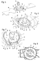
- the in Fig. 1 shown lawnmower 1 is shown as an example of a hand-held implement.
- the invention may also be used in other implements such as choppers, blowers or the like.
- the rotationally driven component is advantageously the impeller for conveying working air.
- the lawnmower 1 has a housing 2, which comprises a protective hood 3. On the guard 3 a total of four wheels 4 are fixed, with which the lawnmower 1 can be pushed over the ground.
- a guide frame 9 is fixed to the protective cover 3, are formed on the handles, not shown.
- a drive motor 5 is arranged, which drives a drive shaft 6 in rotation.
- a blade holder 7 is fixed against rotation.
- a knife 8 is releasably held.
- Fig. 2 shows, the drive shaft 6, the blade holder 7 and the knife 8 are driven to rotate about a rotation axis 10.
- the knife 8 has a center of gravity 12 which has a distance a from the axis of rotation 10.
- the blade holder 7 has a center of gravity 11 which has a distance b from the axis of rotation 10.
- the two focal points 11 and 12 are arranged opposite each other to the axis of rotation 10. Due to the two centers of gravity 11 and 12 arranged at a distance a, b from the axis of rotation 10, there results a center of gravity 13 of the overall system which lies on the axis of rotation 10.
- the centers of gravity 11 and 12 arranged at a distance from the axis of rotation 10 each cause an imbalance.
- the two imbalances are opposite and so large that the overall result is a balanced overall system. In particular, the static imbalances balance out. A small resulting dynamic imbalance can persist.
- the position of the center of gravity 11 causes a radial force acting in the direction of the arrow 32 in operation on the blade holder 7.
- An oppositely directed force in the direction of the arrow 33 acts on the knife 8.
- the force indicated by the arrow 33 is used to fix the knife 8 to the knife receptacle 7.
- the knife has 8 increases, which are formed by beads 30.
- the beads 30 protrude into recesses 31 on the blade holder 7, so that the knife 8 in the in Fig. 2 shown locking position 34 is held without play on the blade holder 7. As a result, a noise during operation due to relative movements between the blade 8 and the blade holder 7 can be avoided.
- Fig. 3 shows the design of the knife 8 in detail.
- Fig. 3 shows the axis of rotation 10 in the geometric center of the knife 8.
- the radially outer side edges of the blade 8 have the axis of rotation 10 the same distance.
- the axis of rotation 10 intersects the knife 8.
- the knife 8 has two cutting edges 15, which are arranged and formed with respect to the axis of rotation 10 opposite one another and symmetrically to the axis of rotation 10.
- the knife 8 is formed substantially rotationally symmetrical to the axis of rotation 10.
- an additional mass 16 is arranged, which is formed as a widened portion of the blade 8. It is thereby achieved that the center of gravity 12 has the distance a from the axis of rotation 10.
- the blade holder 7 is surrounded by a cover 14, which at the in Fig. 1 shown guard 3 is fixed.
- the cover 14 closes the housing 2 towards the blade 8 and thus avoids contamination of the housing interior.
- Fig. 4 shows the knife 8 from the blade receiving 7 side facing.
- side edges 18 are formed in the central region of the longitudinal sides, which are bent in the direction of the blade holder 7.
- the bent side edges 18 increase the stability and the vibration resistance of the blade 8.
- the side edges 18 can be achieved in an easy way to increase the strength of the blade 8.
- two hooks 19 are formed, wherein in each case a hook 19 is arranged on each side of the axis of rotation 10.
- the free end of the hook 19 each has a length e.
- the hooks 19 are open to the additional mass 16 facing side. In operation, the imbalance, the is generated by the additional mass 16, in the direction of the closed side of the hook 19 and thus causes a high holding force of the blade 8 on the blade holder 7.
- a bore 17 is provided in the for balancing of the knife 8, for example, after regrinding, a balancing stone can be used.
- Fig. 5 shows, the hooks 19 protrude through slots 20 in the holding device 7.
- the holding device 7 has a rim 21, the in Fig. 6 and Fig. 7 has openings 22 shown.
- the hooks 19 are in the locking position 34 with its outer edge in the region of the openings 22.
- the hooks 19 do not protrude beyond the edge 21 radially outward.
- the cover 14 has a peripheral edge 25, which is arranged radially outside and adjacent to the edge 21.
- the edge 25 surrounds the edge 21.
- the edge 25 has openings 26 which are in the in Fig. 6 shown position of the blade holder 7 congruent to the openings 22 are. In this position, the blade holder 7, the knife 8 can be pulled in the direction of the arrow 35 from the blade holder 7.
- the edges 21 and 25 are arranged coaxially to the axis of rotation 10.
- a recess 23 is arranged in the region of an opening 26, in which a locking button 24 is provided.
- the locking button 24 closes the aperture 26 and thus limits a radial movement of the Knife 8.
- the locking button 24 must first be pressed by the operator, so that the opening 26 is released. Subsequently, the knife can be moved in the direction of Fig. 6 shown arrow 35 are pushed out of the blade holder 7, so that the hooks 19 come out of the blade holder 7 and the knife 8 can be removed down. Due to the arrangement and orientation of the apertures 26, a loosening or fixing of the knife 8 on the holding device 7 is possible only in this position.
- Fig. 8 shows the position of the knife 8 in the in 6 and 7 shown position.
- the knife 8 is aligned with one end in the direction of an ejection channel 28 of the protective hood 3.
- the protective hood 3 has a distance d from the knife 8 in the radial direction to the axis of rotation 10, which distance is significantly greater than the length e of the free end of the hooks 19.
- the knife 8 can be mounted, or, as indicated by the arrow 29, are released from the blade holder 7.
- the knife 8 has the guard 3 a distance c, which is significantly smaller than the length e of the free portion of the hook 19.
- the movement of the blade 8 is therefore limited by the protective cover 3, before the knife 8 can be released from the blade holder 7.
- the limitation of the movement through the protective hood 3 is redundant for the limitation by the edge 25 with the apertures 26 (FIG. Fig. 7 ) and provides an additional backup in case of failure of the edge 25 and the hook 19.
- the blade holder 7 has an additional mass 27 which is fixed to a base plate 36 of the blade holder 7 and which limits the slots for the hooks 19 partially.
- the additional mass 27 forms the imbalance of the blade holder 7.
- the additional mass 27 generates a radial force which compensates for the radial force generated by the additional mass 16 of the blade 8.
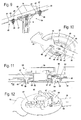
- FIGS. 9 and 10 show a further embodiment of a knife 38 which is held on a blade holder 37.
- the knife has 38 keyhole-like openings 40 into the retaining pin 39 of the blade holder 37 protrude.
- the openings 40 each have an inlet opening 41 of increased diameter and an adjoining, in the direction of the longitudinal central axis of the knife 38 extending slot 42.
- the retaining bolts 39 each have a head 47 which engages behind the edge region of the slot 42, and thus secures the knife 38 ,
- the blade holder 37 has as an additional securing means a spring 43 which is formed as a helical compression spring and the knife 38 in the in Fig. 9 shown locking position 34 presses. As a result, it is ensured even when the drive shaft 6 is at a standstill that the blade 38 is held on the blade holder 37.
- the knife 38 also has an additional mass 16 which exerts a force in the direction of the arrow 33 during operation. As a result, the knife 38 is pressed against the retaining pin 39 away from the inlet opening 41 into the slot 42. As a result, the knife 38 is safe in operation on the blade holder 37 held.
- the blade holder 37 has a lock button 44 which has a nose 45. The latch 45 protrudes into an opening 46 on the cover 14. The latch button 44 is spring-loaded and presses against the blade 38.
- the latch 45 is moved into the plane of the cover 14 preventing it a rotary movement of the blade holder 37.
- a recess 49 is provided, into which a in Fig. 10 not shown projection protrudes in the locking position 34.
- the locking button 44 springs back and moves the nose 45 out of the opening 46.
- the opening 46 is arranged in an edge 48 of the cover 14, which surrounds the blade holder 37 concentrically with the axis of rotation 10.
- the nose 45 is not blocked by the edge 48, and the blade holder 37 can be driven in rotation.
- the locking button 44 thus prevents a rotational movement of the blade holder 37 when the knife 38 is not arranged correctly in the locking position 34.
- the blade holder 37 is rotatable.
- a knife 58 is provided which is held on a blade holder 57.
- the knife 58 also has an in Fig. 11 not shown imbalance, which acts in the direction of the arrow 33.
- the knife 58 has two retaining bolts 59, each having a head 67 of increased diameter.
- At the knife holder 57 are formed two openings 60, which are each keyhole-shaped and which have an inlet opening 61 through which the head 67 can pass, and a longitudinal direction of the knife 58 extending, narrower slit 62 which connects to the inlet opening 61.
- the slot 62 has an edge 66 which surrounds the head 67 of the retaining bolts 59 in the in Fig. 11 engages behind shown locking position 34.
- a retaining bolt 63 is provided on the holding device 57, which is mounted pivotably about a pivot axis 68.
- the retaining bolt 63 protrudes into the area of the inlet opening 61 of the opening 60 and blocks it, so that the retaining bolt 59 can not reach the area of the inlet opening 61. As a result, unintentional release of the knife 58 is avoided.
- the retaining bolt 63 is covered by a locking plate 64.
- the locking plate 64 covers a predetermined angular range, which corresponds to the expansion position of the blade 58. This avoids that the retaining latch swings up in this angular range and the knife can turn off automatically.
- the retaining latch 68 To release the knife 58 from the blade holder 57, the retaining latch 68 must first pivot outward. To remove the blade 58, the implement, so the lawnmower 1, usually rotated. When turning over the lawn mower 1 of the retaining latch 58 falls outside, if it is not located in a covered by the locking plate 64 area.
- the operator then only has to turn the knife 58 into the removal position and move it laterally, so that the retaining bolts 59 are guided through the openings 60 can. If the retaining bolt 63 is arranged in the region of the securing plate 64 when the working implement is tilted, the operator must first manually turn the blade receptacle 57 until the retaining bolt 63 comes out of the region of the securing plate 64 and falls outward. Subsequently, the blade holder 57 must be turned back so that the knife 58 is in the extended position and can be moved laterally.
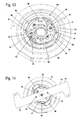
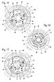
- the Fig. 13 to 20 show a knife receptacle 77 on which a knife 78 (FIG. Fig. 14 ) is releasably held.
- the knife 78 has no additional mass.
- the knife 78 is balanced about the axis of rotation 10.
- the knife 78 has two mutually opposite to the axis of rotation 10 oppositely disposed cutting 15.
- On the knife 78 two retaining pins 79 are fixed on both sides to the axis of rotation 10, which protrude to the blade holder 77.
- the knife holder 77 is surrounded by a cover 14. Adjacent to the blade holder 77, the cover 14 has two gripping recesses 89 arranged opposite one another.
- the blade holder 77 has two unlocking sections 90, which are likewise arranged opposite one another.
- the unlocking sections 90 are formed as operating sections and are actuated for unlocking by an operator.
- the Entriegelungsabête 90 can not be operated by the operator, as they are not in registration with the recessed grips 89.
- An actuation of the Entriegelungsabête 90 is prevented by the cover 14, which extends radially outwardly of the blade holder 77 and the Entriegelungsabête 90.
- Fig. 13 shows a view of the blade holder 77 of the knife 78 side facing.
- the knife holder 77 comprises two centrifugal pawls 80, which are each mounted pivotably about a pivot axis 81.
- Both centrifugal pawls 80 extend approximately semicircular in the region of an edge 87, which is integrally formed on the cover 14.
- the arrangement of the edge 87 on the cover 14 is in the FIGS. 19 and 20 shown.
- each centrifugal force pawl 80 has in the region of its free end an opening 82 which is keyhole-shaped and which has an inlet opening 83 and a subsequent to the inlet opening 83 slot 84.
- the slot 84 extends from the inlet opening 83 to the free end of the centrifugal pawl 80 out.
- the retaining bolts 79 of the blade 78 are held.
- a spring 85 is arranged on the blade holder 77, whose function will be explained in more detail below.
- the centrifugal pawls 80 each have a locking projection 86, which in the in Fig. 13 shown locking position 100 of the centrifugal pawls 80 relative to the axis of rotation 10 radially outside of the edge 87 is located.
- the in Fig. 13 shown locking position 100 of the centrifugal pawls 80 relative to the axis of rotation 10 radially outside of the edge 87 is located.
- FIG. 15 schematically shows the centrifugal force pawls 80 by springs 96 radially outward, ie in the direction of their Locking position 100 spring loaded.
- the retaining bolts 79 are arranged in the locking position 100 in the region of the slots 84 and engage behind the slots 84, so that the blade 78 is fixed in the direction of the axis of rotation 10 on the blade holder 77.
- the edge 87 has two openings 88, the width of which approximately corresponds to the width of the locking projections 86, each measured in the circumferential direction to the axis of rotation 10.
- the locking projections 86 are radially outside of the openings 88th Wie Fig. 18 shows, the recessed grips 89 are arranged in this position congruent to the Entriegelungsabismeen 90.
- the operator can operate the unlocking sections 90 by gripping in the region of the recessed grips 89.
- the Entriegelungsabitese 90 are firmly connected to the centrifugal pawls 80.
- the centrifugal pawls 80 are pivoted radially inwardly.
- the locking projections 86 enter the openings 88.
- the openings 82 on the centrifugal force pawls 80 move relative to the retaining bolts 79, so that the retaining bolts 79 reach the region of the inlet openings 83.
- the operator must operate the unlocking portions 90 against the force of the springs 96.
- Fig. 19 shows the blade holder 77 before operating the Entriegelungsabritte 90.
- the locking projection 86 is located before breakthrough 88 and radially outward of edge 87.
- the blade holder 77 is formed by a blade 78 facing the cover plate 93 and a base plate 94, between which the centrifugal pawls 80 are arranged.
- the retaining bolts 79 protrude into the intermediate space formed between the two plates 93 and 94.
- the plates 93, 94 are bolted together by fastening screws 95 from the side facing the blade 78.
- the spring 85 is pressed by the retaining pin 79 down.
- the spring 85 is fixed to the base plate 94 in the region of the opening 82.
- the opening 82 has in the region of the slot 84 has an edge 91 which is formed at its transverse to the longitudinal center axis 99 of the retaining bolt 79 walls 97 obliquely.
- the walls 97 run towards each other in the direction of the center of the slot 84.
- the retaining pin 79 has a recess 92 which is advantageously formed as a circumferential groove, and their lying transverse to the longitudinal center axis 99 walls 98 are also arranged obliquely to the longitudinal central axis 99, and at an angle which is approximately the inclination angle of the wall 97 at the edge 91 of the slot 84 corresponds. Due to the inclination of the walls 97 and 98 of the retaining pin 79 is held without play in the slot 84. It can also be provided that the blade 78 is clamped against the cover plate 93 due to the inclination of the walls 97 and 98. The angle by which the walls 97 and 98 are inclined is greater than the angle for the self-locking.
- Fig. 20 shows the knife holder 77 in the release position 101.
- the Entriegelungsabête 90 are pressed and the centrifugal pawls 80 pivoted inward.
- the retaining bolts 79 are located in the region of the inlet opening 83 of the opening 82.
- the spring 85 is lifted from the cover plate 94 and has moved the retaining pin 79 away from the blade holder 77.
- the free end 102 of the spring 85 is engaged at the edge of the opening 82 and holds the centrifugal pawls 80 in their release position 101.
- the spring 85 is pressed down and releases the centrifugal pawls 80 free , Due to the power of in FIGS.
- FIGS. 21 to 31 show as an exemplary embodiment of a working implement a chopper 105.
- the chopper 105 has a housing 106 in which a drive motor 107 is arranged.
- the drive motor 107 is designed as an electric motor and drives a drive shaft 108 about an axis of rotation 116 to rotate.
- On the drive shaft 108 a blade holder 109 is fixed against rotation.
- the knife holder 109 serves to receive a knife disk 110.
- the cutter disk 110 is covered by a protective hood 111 of the housing 106. Below the cutter disk 110, an ejection channel 113 is provided for ejecting crops.
- the protective hood 111 has an edge 114 which engages over the cutter disk 110 at its outer circumference at a small radial distance when the cutter disk 110 is correctly mounted.
- an additional mass 115 is fixed to the blade receptacle 109 on the underside facing away from the cutter disk 110.
- FIGS. 23 to 27 show the structure of the cutter disk 110 and the blade holder 109 in detail.
- the knife disk 110 has a knife carrier 117, which is designed as a substantially flat plate.
- On the knife carrier 117 two chopping blades 118, two cutting blades 119 and two razor blades 120 are provided opposite each other.
- Each of the knives 118, 119, 120 has a cutting edge 121.
- the cutter disk 110 has an opening 123 which is provided in the knife carrier 117.
- the opening 123 comprises a slot 124 which connects to an inlet opening 125.
- the slot 124 is in Fig. 28 shown and in the FIGS. 23 to 27 obscured by a nozzle 136 of the blade holder 109.
- Fig. 24 shows, two additional masses 122 are attached to the cutter disk 110 on the underside of the blade disk 110 facing the blade receptacle 109.
- the two additional masses 122 generate a static imbalance in operation, which is opposite and equal to the imbalance caused by the additional mass 115 on the blade holder 109.
- the entire system no longer has static imbalance.
- the same caused by the additional masses 115, 122 dynamic imbalances substantially from.
- the two additional masses 122 mean that the center of gravity of the cutter disk 110 is at a distance from the axis of rotation 116.
- the focus of the blade receptacle 109 is due to the arrangement of the additional mass 115 on the opposite side of the rotation axis 116 and also at a distance from the rotation axis 116th
- the blade receptacle 109 has an opening 126 which includes a slot 127 and an inlet opening 128. With the opening 126, a tab 129 of the cutter disk 110 acts together. The tab 129 is bent out of the plane of the knife carrier 117 down. In the in Fig. 24 shown locking position of the cutter disk 110 engage behind the lateral portions 130 of the T-shaped tab 129, the lateral edges of the slot 127 and fix the blade plate 110 so in the direction of the axis of rotation 116. Wie Fig. 24 also shows, the cutter disk 110 has laterally of the additional mass 115 two hooks 133, which engage under a portion of the blade receptacle 109 and thus also cause a fixation of the cutter disk 110.
- Each hook 133 is closed in the direction in which the inlet opening 128 is based on the slot 127.
- the cutter disk 110 can be displaced radially relative to the knife holder 109 in relation to the axis of rotation 116 for releasing.
- the additional mass 115 is composed of a plurality of sheets, which are screwed with two fastening screws 135 on the blade holder 109.
- the knife holder 109 has a receptacle 134 for the drive shaft 108, which is formed in the region of the nozzle 136.
- the receptacle 134 has a flattening, so that the blade holder 109 is rotatably held on the drive shaft 108.
- the knife disc 110 is arranged on the neck 136.
- a holding plate 131 is provided on the side facing away from the drive motor 107 top end of the nozzle 136.
- the holding plate 131 is T-shaped and has lateral portions 132.
- the inlet opening 125 of the opening 123 in the knife carrier 117 also has a T-shape corresponding to that of the holding plate 131. If the cutter disk 110 is fixed to the blade holder 109, the lateral portions 132 engage behind the side edges of the slot 124 and thereby fix the cutter disk 110 together with the lateral portions 130.
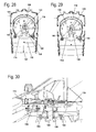
- Fig. 28 shows the cutter disk 110 in the removal position 139. In this position, the cutter disk is displaced in the direction of the arrow 137 relative to the blade holder 109.
- the holding plate 131 is congruent to the inlet opening 125.
- the stub 136 ( Fig. 26 ) has exited the slot 124.
- the edge 114 of the protective cover 111 is in this position of the cutter disk 110 in the region of Knife disk 110. As a result, the protective cover 111 can not be closed.
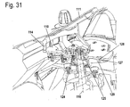
- Fig. 30 shows, in this position, the cutter disk 110, the slot 124 is free and the nozzle 136 is disposed in the inlet opening 125 ( Fig. 31 ). Also, the tab 129 is disposed in the region of the inlet opening 128, so that the slot 127 is free.
- the blade disk 110 can be removed from the blade receptacle 109 in the axial direction to the rotation axis 116. Due to the design of the rim 114, the protective hood 111 can not be closed in this position. Usually, in choppers or the like. The operation is not possible if the protective hood 111 is not closed. The fact that the protective hood 111 can only be closed when the cutter disk 110 is correctly mounted ensures that an operation is not possible if the cutter disk 110 is not mounted correctly.
- Fig. 29 the cutter disk 110 is shown in the locked position 138, ie in the correctly mounted state.
- the edge 114 is arranged on the outer circumference of the cutter disk 110, so that the protective cover 111 can be closed.
- the holding plate 131 engages behind the slot 124.
- the hooks 133 engage behind the blade receptacle 109 and the tab 129 engages behind the slot 127.
- the blade disc 110 is thereby fixed in the axial direction on the blade receptacle 109.
- the additional masses 122 are arranged in such a way that they have a force during operation, that is, during a rotation about the axis of rotation 116 the knife disc 110 in the direction of the locking position 138 exercise.
- the knife disk 110 is thereby pressed during operation in the locked position, so that unintentional release is not possible. Due to the force resulting from the additional masses 122, the cutter disk 110 is held on the blade holder 109.
- FIGS. 28 and 29 show recesses 140 are provided on the cutter disk 110, which allow the cutter disk 110 can be moved radially to the rotation axis 116 for removal.
- the knife disk 110 may be in the in Fig. 28 shown position to be shifted in the direction of the discharge channel 113. An expansion of the cutter disk 110 is possible only in this predetermined position. In other positions of the cutter disk 110, the movement of the cutter disk 110 is limited by the housing 106. In operation, a radial movement of the cutter disk 110 is limited by the protective cover 111.
Landscapes
- Life Sciences & Earth Sciences (AREA)
- Environmental Sciences (AREA)
- Harvester Elements (AREA)
- Magnetically Actuated Valves (AREA)
Applications Claiming Priority (1)
| Application Number | Priority Date | Filing Date | Title |
|---|---|---|---|
| DE102008064068A DE102008064068A1 (de) | 2008-12-19 | 2008-12-19 | Arbeitsgerät |
Publications (2)
| Publication Number | Publication Date |
|---|---|
| EP2198686A1 true EP2198686A1 (fr) | 2010-06-23 |
| EP2198686B1 EP2198686B1 (fr) | 2011-01-12 |
Family
ID=41820829
Family Applications (1)
| Application Number | Title | Priority Date | Filing Date |
|---|---|---|---|
| EP09014925A Active EP2198686B1 (fr) | 2008-12-19 | 2009-12-02 | Appareil de travail |
Country Status (3)
| Country | Link |
|---|---|
| EP (1) | EP2198686B1 (fr) |
| AT (1) | ATE494769T1 (fr) |
| DE (2) | DE102008064068A1 (fr) |
Cited By (4)
| Publication number | Priority date | Publication date | Assignee | Title |
|---|---|---|---|---|
| WO2013155101A1 (fr) * | 2012-04-11 | 2013-10-17 | Briggs & Stratton Corporation | Lame de tondeuse réduisant le bruit |
| CN103535152A (zh) * | 2013-10-31 | 2014-01-29 | 苏州安必瑟斯机电技术有限公司 | 切割刀片 |
| CN108419504A (zh) * | 2018-05-21 | 2018-08-21 | 浙江亚特电器有限公司 | 一种旋刀式割草机的切割刀片及旋刀式割草机 |
| WO2025020938A1 (fr) * | 2023-07-21 | 2025-01-30 | 追觅科技(苏州)有限公司 | Structure d'assemblage et de désassemblage d'élément de coupe et tondeuse |
Families Citing this family (2)
| Publication number | Priority date | Publication date | Assignee | Title |
|---|---|---|---|---|
| CN102771248B (zh) * | 2012-08-01 | 2014-04-16 | 无锡市新菊电动工具有限公司 | 打草机刀片快换机构 |
| EP2966967B1 (fr) | 2013-03-14 | 2019-08-14 | Husqvarna AB | Lames de faucheuse à raccord rapide |
Citations (7)
| Publication number | Priority date | Publication date | Assignee | Title |
|---|---|---|---|---|
| US5036654A (en) * | 1990-09-14 | 1991-08-06 | Malutich William J | Replaceable cutting blade for rotary lawn mower |
| EP0486459A1 (fr) * | 1990-11-16 | 1992-05-20 | Franz Jetzinger | Fixation d'outil pour récolteuses-hacheuses |
| US6119350A (en) * | 1997-05-23 | 2000-09-19 | Trim-A-Lawn Corporation | Rotary cutting member for lawn trimmers |
| DE10036552A1 (de) * | 2000-07-27 | 2002-02-07 | Karl Moosbrucker | Messerklingenbefestigung für Kreiselmähwerke |
| EP1358786A1 (fr) * | 2002-04-29 | 2003-11-05 | MOGATEC Moderne Gartentechnik GmbH | Support de lame pour une tête de coupe rotative d'un appareil de coupe de plantes |
| US20080010836A1 (en) * | 2006-07-12 | 2008-01-17 | Kwik Products, Inc. | Three-in-one trimmer head |
| EP1891851A1 (fr) * | 2006-08-24 | 2008-02-27 | Kuhn S.A. | Dispositif de fixation rapide et sécurisé d'un couteau de machine de fauchage |
Family Cites Families (1)
| Publication number | Priority date | Publication date | Assignee | Title |
|---|---|---|---|---|
| US4712364A (en) | 1986-06-30 | 1987-12-15 | Deere & Company | Quick attachable and detachable mower blade assembly |
-
2008
- 2008-12-19 DE DE102008064068A patent/DE102008064068A1/de not_active Withdrawn
-
2009
- 2009-12-02 EP EP09014925A patent/EP2198686B1/fr active Active
- 2009-12-02 DE DE502009000290T patent/DE502009000290D1/de active Active
- 2009-12-02 AT AT09014925T patent/ATE494769T1/de active
Patent Citations (7)
| Publication number | Priority date | Publication date | Assignee | Title |
|---|---|---|---|---|
| US5036654A (en) * | 1990-09-14 | 1991-08-06 | Malutich William J | Replaceable cutting blade for rotary lawn mower |
| EP0486459A1 (fr) * | 1990-11-16 | 1992-05-20 | Franz Jetzinger | Fixation d'outil pour récolteuses-hacheuses |
| US6119350A (en) * | 1997-05-23 | 2000-09-19 | Trim-A-Lawn Corporation | Rotary cutting member for lawn trimmers |
| DE10036552A1 (de) * | 2000-07-27 | 2002-02-07 | Karl Moosbrucker | Messerklingenbefestigung für Kreiselmähwerke |
| EP1358786A1 (fr) * | 2002-04-29 | 2003-11-05 | MOGATEC Moderne Gartentechnik GmbH | Support de lame pour une tête de coupe rotative d'un appareil de coupe de plantes |
| US20080010836A1 (en) * | 2006-07-12 | 2008-01-17 | Kwik Products, Inc. | Three-in-one trimmer head |
| EP1891851A1 (fr) * | 2006-08-24 | 2008-02-27 | Kuhn S.A. | Dispositif de fixation rapide et sécurisé d'un couteau de machine de fauchage |
Cited By (5)
| Publication number | Priority date | Publication date | Assignee | Title |
|---|---|---|---|---|
| WO2013155101A1 (fr) * | 2012-04-11 | 2013-10-17 | Briggs & Stratton Corporation | Lame de tondeuse réduisant le bruit |
| US9888626B2 (en) | 2012-04-11 | 2018-02-13 | Briggs & Stratton Corporation | Noise-reducing mower blade |
| CN103535152A (zh) * | 2013-10-31 | 2014-01-29 | 苏州安必瑟斯机电技术有限公司 | 切割刀片 |
| CN108419504A (zh) * | 2018-05-21 | 2018-08-21 | 浙江亚特电器有限公司 | 一种旋刀式割草机的切割刀片及旋刀式割草机 |
| WO2025020938A1 (fr) * | 2023-07-21 | 2025-01-30 | 追觅科技(苏州)有限公司 | Structure d'assemblage et de désassemblage d'élément de coupe et tondeuse |
Also Published As
| Publication number | Publication date |
|---|---|
| EP2198686B1 (fr) | 2011-01-12 |
| DE102008064068A1 (de) | 2010-07-01 |
| ATE494769T1 (de) | 2011-01-15 |
| DE502009000290D1 (de) | 2011-02-24 |
Similar Documents
| Publication | Publication Date | Title |
|---|---|---|
| EP2198686B1 (fr) | Appareil de travail | |
| EP3888441B1 (fr) | Barre de coupe pour une tondeuse à gazon et/ou une motofaucheuse, tondeuse à gazon et/ou motofaucheuse et procédé de montage d'une barre de coupe et/ou d'une tondeuse à gazon et/ou d'une motofaucheuse | |
| DE1757596A1 (de) | Maehmesser-Halterung | |
| EP1570719B1 (fr) | Appareil de coupage, en particulier tondeuse â gazon | |
| DE10036458A1 (de) | Staubfangvorrichtung für eine Säge | |
| DE102016210183A1 (de) | Mulchkitsteuerhebel | |
| EP3360405B1 (fr) | Tête de coupe pour une débroussailleuse | |
| EP1029436A2 (fr) | Fixation, faucheuse et véhicule resp. appareil de travail | |
| WO1995005273A1 (fr) | Corps de coupe | |
| EP2677910B1 (fr) | Outil et dispositif d'entraînement pour appareil de cuisine commandé par un moteur | |
| EP1358786B1 (fr) | Support de lame pour une tête de coupe rotative d'un appareil de coupe de plantes | |
| AT520377B1 (de) | Wurfvorrichtung zum Auswerfen von Hackgut | |
| EP2559363B1 (fr) | Outil pour un appareil de cuisine motorisé ainsi qu'appareil de cuisine | |
| EP2621320B1 (fr) | Lame de râpe réglable | |
| DE10219181B4 (de) | Schneidkopf für eine motorbetriebene Vorrichtung zum Schneiden von Pflanzen | |
| EP1547459B1 (fr) | Disque de coupe avec dents déchirantes pour un broyeur | |
| DE102012112621A1 (de) | Handwerkzeugmaschine mit abnehmbarer Schutzhaube | |
| EP1721514B1 (fr) | Hache-paille | |
| EP0089571B1 (fr) | Désintégrateur du bois | |
| EP1201310A1 (fr) | Arbre et dispositif avec un arbre pour broyage de déchets | |
| DE1193721B (de) | Haeckselmaschine fuer landwirtschaftliche Produkte, insbesondere Scheibenradhaecksler | |
| DE29702876U1 (de) | Laborschneidmühle mit Faltdeckel | |
| DE60216990T2 (de) | Messerbefestigung | |
| EP1967271A1 (fr) | Lame de couteau | |
| DE8524307U1 (de) | Gartenhäcksler mit Anlaufsicherung |
Legal Events
| Date | Code | Title | Description |
|---|---|---|---|
| PUAI | Public reference made under article 153(3) epc to a published international application that has entered the european phase |
Free format text: ORIGINAL CODE: 0009012 |
|
| AK | Designated contracting states |
Kind code of ref document: A1 Designated state(s): AT BE BG CH CY CZ DE DK EE ES FI FR GB GR HR HU IE IS IT LI LT LU LV MC MK MT NL NO PL PT RO SE SI SK SM TR |
|
| AX | Request for extension of the european patent |
Extension state: AL BA RS |
|
| GRAP | Despatch of communication of intention to grant a patent |
Free format text: ORIGINAL CODE: EPIDOSNIGR1 |
|
| 17P | Request for examination filed |
Effective date: 20100702 |
|
| RIC1 | Information provided on ipc code assigned before grant |
Ipc: A01D 34/73 20060101AFI20100804BHEP Ipc: A01F 29/09 20100101ALI20100804BHEP |
|
| GRAS | Grant fee paid |
Free format text: ORIGINAL CODE: EPIDOSNIGR3 |
|
| GRAA | (expected) grant |
Free format text: ORIGINAL CODE: 0009210 |
|
| AK | Designated contracting states |
Kind code of ref document: B1 Designated state(s): AT BE BG CH CY CZ DE DK EE ES FI FR GB GR HR HU IE IS IT LI LT LU LV MC MK MT NL NO PL PT RO SE SI SK SM TR |
|
| REG | Reference to a national code |
Ref country code: GB Ref legal event code: FG4D Free format text: NOT ENGLISH |
|
| REG | Reference to a national code |
Ref country code: CH Ref legal event code: EP |
|
| REG | Reference to a national code |
Ref country code: IE Ref legal event code: FG4D Free format text: LANGUAGE OF EP DOCUMENT: GERMAN |
|
| REF | Corresponds to: |
Ref document number: 502009000290 Country of ref document: DE Date of ref document: 20110224 Kind code of ref document: P |
|
| REG | Reference to a national code |
Ref country code: DE Ref legal event code: R096 Ref document number: 502009000290 Country of ref document: DE Effective date: 20110224 |
|
| REG | Reference to a national code |
Ref country code: SE Ref legal event code: TRGR |
|
| REG | Reference to a national code |
Ref country code: NL Ref legal event code: VDEP Effective date: 20110112 |
|
| LTIE | Lt: invalidation of european patent or patent extension |
Effective date: 20110112 |
|
| PG25 | Lapsed in a contracting state [announced via postgrant information from national office to epo] |
Ref country code: LT Free format text: LAPSE BECAUSE OF FAILURE TO SUBMIT A TRANSLATION OF THE DESCRIPTION OR TO PAY THE FEE WITHIN THE PRESCRIBED TIME-LIMIT Effective date: 20110112 Ref country code: LV Free format text: LAPSE BECAUSE OF FAILURE TO SUBMIT A TRANSLATION OF THE DESCRIPTION OR TO PAY THE FEE WITHIN THE PRESCRIBED TIME-LIMIT Effective date: 20110112 Ref country code: HR Free format text: LAPSE BECAUSE OF FAILURE TO SUBMIT A TRANSLATION OF THE DESCRIPTION OR TO PAY THE FEE WITHIN THE PRESCRIBED TIME-LIMIT Effective date: 20110112 Ref country code: NO Free format text: LAPSE BECAUSE OF FAILURE TO SUBMIT A TRANSLATION OF THE DESCRIPTION OR TO PAY THE FEE WITHIN THE PRESCRIBED TIME-LIMIT Effective date: 20110412 Ref country code: GR Free format text: LAPSE BECAUSE OF FAILURE TO SUBMIT A TRANSLATION OF THE DESCRIPTION OR TO PAY THE FEE WITHIN THE PRESCRIBED TIME-LIMIT Effective date: 20110413 Ref country code: PT Free format text: LAPSE BECAUSE OF FAILURE TO SUBMIT A TRANSLATION OF THE DESCRIPTION OR TO PAY THE FEE WITHIN THE PRESCRIBED TIME-LIMIT Effective date: 20110512 Ref country code: IS Free format text: LAPSE BECAUSE OF FAILURE TO SUBMIT A TRANSLATION OF THE DESCRIPTION OR TO PAY THE FEE WITHIN THE PRESCRIBED TIME-LIMIT Effective date: 20110512 Ref country code: ES Free format text: LAPSE BECAUSE OF FAILURE TO SUBMIT A TRANSLATION OF THE DESCRIPTION OR TO PAY THE FEE WITHIN THE PRESCRIBED TIME-LIMIT Effective date: 20110423 |
|
| REG | Reference to a national code |
Ref country code: IE Ref legal event code: FD4D |
|
| PG25 | Lapsed in a contracting state [announced via postgrant information from national office to epo] |
Ref country code: CY Free format text: LAPSE BECAUSE OF FAILURE TO SUBMIT A TRANSLATION OF THE DESCRIPTION OR TO PAY THE FEE WITHIN THE PRESCRIBED TIME-LIMIT Effective date: 20110112 Ref country code: BG Free format text: LAPSE BECAUSE OF FAILURE TO SUBMIT A TRANSLATION OF THE DESCRIPTION OR TO PAY THE FEE WITHIN THE PRESCRIBED TIME-LIMIT Effective date: 20110412 Ref country code: FI Free format text: LAPSE BECAUSE OF FAILURE TO SUBMIT A TRANSLATION OF THE DESCRIPTION OR TO PAY THE FEE WITHIN THE PRESCRIBED TIME-LIMIT Effective date: 20110112 Ref country code: SI Free format text: LAPSE BECAUSE OF FAILURE TO SUBMIT A TRANSLATION OF THE DESCRIPTION OR TO PAY THE FEE WITHIN THE PRESCRIBED TIME-LIMIT Effective date: 20110112 Ref country code: PL Free format text: LAPSE BECAUSE OF FAILURE TO SUBMIT A TRANSLATION OF THE DESCRIPTION OR TO PAY THE FEE WITHIN THE PRESCRIBED TIME-LIMIT Effective date: 20110112 Ref country code: NL Free format text: LAPSE BECAUSE OF FAILURE TO SUBMIT A TRANSLATION OF THE DESCRIPTION OR TO PAY THE FEE WITHIN THE PRESCRIBED TIME-LIMIT Effective date: 20110112 |
|
| PG25 | Lapsed in a contracting state [announced via postgrant information from national office to epo] |
Ref country code: IE Free format text: LAPSE BECAUSE OF FAILURE TO SUBMIT A TRANSLATION OF THE DESCRIPTION OR TO PAY THE FEE WITHIN THE PRESCRIBED TIME-LIMIT Effective date: 20110112 Ref country code: EE Free format text: LAPSE BECAUSE OF FAILURE TO SUBMIT A TRANSLATION OF THE DESCRIPTION OR TO PAY THE FEE WITHIN THE PRESCRIBED TIME-LIMIT Effective date: 20110112 Ref country code: DK Free format text: LAPSE BECAUSE OF FAILURE TO SUBMIT A TRANSLATION OF THE DESCRIPTION OR TO PAY THE FEE WITHIN THE PRESCRIBED TIME-LIMIT Effective date: 20110112 |
|
| PLBE | No opposition filed within time limit |
Free format text: ORIGINAL CODE: 0009261 |
|
| STAA | Information on the status of an ep patent application or granted ep patent |
Free format text: STATUS: NO OPPOSITION FILED WITHIN TIME LIMIT |
|
| PG25 | Lapsed in a contracting state [announced via postgrant information from national office to epo] |
Ref country code: CZ Free format text: LAPSE BECAUSE OF FAILURE TO SUBMIT A TRANSLATION OF THE DESCRIPTION OR TO PAY THE FEE WITHIN THE PRESCRIBED TIME-LIMIT Effective date: 20110112 Ref country code: RO Free format text: LAPSE BECAUSE OF FAILURE TO SUBMIT A TRANSLATION OF THE DESCRIPTION OR TO PAY THE FEE WITHIN THE PRESCRIBED TIME-LIMIT Effective date: 20110112 Ref country code: SK Free format text: LAPSE BECAUSE OF FAILURE TO SUBMIT A TRANSLATION OF THE DESCRIPTION OR TO PAY THE FEE WITHIN THE PRESCRIBED TIME-LIMIT Effective date: 20110112 |
|
| 26N | No opposition filed |
Effective date: 20111013 |
|
| REG | Reference to a national code |
Ref country code: DE Ref legal event code: R097 Ref document number: 502009000290 Country of ref document: DE Effective date: 20111013 |
|
| PG25 | Lapsed in a contracting state [announced via postgrant information from national office to epo] |
Ref country code: MC Free format text: LAPSE BECAUSE OF NON-PAYMENT OF DUE FEES Effective date: 20111231 |
|
| PG25 | Lapsed in a contracting state [announced via postgrant information from national office to epo] |
Ref country code: MK Free format text: LAPSE BECAUSE OF FAILURE TO SUBMIT A TRANSLATION OF THE DESCRIPTION OR TO PAY THE FEE WITHIN THE PRESCRIBED TIME-LIMIT Effective date: 20110112 Ref country code: MT Free format text: LAPSE BECAUSE OF FAILURE TO SUBMIT A TRANSLATION OF THE DESCRIPTION OR TO PAY THE FEE WITHIN THE PRESCRIBED TIME-LIMIT Effective date: 20110112 |
|
| PG25 | Lapsed in a contracting state [announced via postgrant information from national office to epo] |
Ref country code: SM Free format text: LAPSE BECAUSE OF FAILURE TO SUBMIT A TRANSLATION OF THE DESCRIPTION OR TO PAY THE FEE WITHIN THE PRESCRIBED TIME-LIMIT Effective date: 20110112 |
|
| PG25 | Lapsed in a contracting state [announced via postgrant information from national office to epo] |
Ref country code: LU Free format text: LAPSE BECAUSE OF NON-PAYMENT OF DUE FEES Effective date: 20111202 |
|
| PG25 | Lapsed in a contracting state [announced via postgrant information from national office to epo] |
Ref country code: TR Free format text: LAPSE BECAUSE OF FAILURE TO SUBMIT A TRANSLATION OF THE DESCRIPTION OR TO PAY THE FEE WITHIN THE PRESCRIBED TIME-LIMIT Effective date: 20110112 |
|
| PG25 | Lapsed in a contracting state [announced via postgrant information from national office to epo] |
Ref country code: HU Free format text: LAPSE BECAUSE OF FAILURE TO SUBMIT A TRANSLATION OF THE DESCRIPTION OR TO PAY THE FEE WITHIN THE PRESCRIBED TIME-LIMIT Effective date: 20110112 |
|
| REG | Reference to a national code |
Ref country code: CH Ref legal event code: PL |
|
| PG25 | Lapsed in a contracting state [announced via postgrant information from national office to epo] |
Ref country code: CH Free format text: LAPSE BECAUSE OF NON-PAYMENT OF DUE FEES Effective date: 20131231 Ref country code: LI Free format text: LAPSE BECAUSE OF NON-PAYMENT OF DUE FEES Effective date: 20131231 |
|
| REG | Reference to a national code |
Ref country code: FR Ref legal event code: PLFP Year of fee payment: 7 |
|
| REG | Reference to a national code |
Ref country code: AT Ref legal event code: MM01 Ref document number: 494769 Country of ref document: AT Kind code of ref document: T Effective date: 20141202 |
|
| PG25 | Lapsed in a contracting state [announced via postgrant information from national office to epo] |
Ref country code: AT Free format text: LAPSE BECAUSE OF NON-PAYMENT OF DUE FEES Effective date: 20141202 |
|
| REG | Reference to a national code |
Ref country code: FR Ref legal event code: PLFP Year of fee payment: 8 |
|
| REG | Reference to a national code |
Ref country code: FR Ref legal event code: PLFP Year of fee payment: 9 |
|
| PGFP | Annual fee paid to national office [announced via postgrant information from national office to epo] |
Ref country code: FR Payment date: 20171226 Year of fee payment: 9 |
|
| PGFP | Annual fee paid to national office [announced via postgrant information from national office to epo] |
Ref country code: SE Payment date: 20171229 Year of fee payment: 9 Ref country code: BE Payment date: 20171221 Year of fee payment: 9 Ref country code: GB Payment date: 20171228 Year of fee payment: 9 |
|
| PGFP | Annual fee paid to national office [announced via postgrant information from national office to epo] |
Ref country code: IT Payment date: 20171220 Year of fee payment: 9 |
|
| REG | Reference to a national code |
Ref country code: SE Ref legal event code: EUG |
|
| PG25 | Lapsed in a contracting state [announced via postgrant information from national office to epo] |
Ref country code: SE Free format text: LAPSE BECAUSE OF NON-PAYMENT OF DUE FEES Effective date: 20181203 |
|
| GBPC | Gb: european patent ceased through non-payment of renewal fee |
Effective date: 20181202 |
|
| REG | Reference to a national code |
Ref country code: BE Ref legal event code: MM Effective date: 20181231 |
|
| PG25 | Lapsed in a contracting state [announced via postgrant information from national office to epo] |
Ref country code: FR Free format text: LAPSE BECAUSE OF NON-PAYMENT OF DUE FEES Effective date: 20181231 Ref country code: IT Free format text: LAPSE BECAUSE OF NON-PAYMENT OF DUE FEES Effective date: 20181202 |
|
| PG25 | Lapsed in a contracting state [announced via postgrant information from national office to epo] |
Ref country code: BE Free format text: LAPSE BECAUSE OF NON-PAYMENT OF DUE FEES Effective date: 20181231 |
|
| PG25 | Lapsed in a contracting state [announced via postgrant information from national office to epo] |
Ref country code: GB Free format text: LAPSE BECAUSE OF NON-PAYMENT OF DUE FEES Effective date: 20181202 |
|
| PGFP | Annual fee paid to national office [announced via postgrant information from national office to epo] |
Ref country code: DE Payment date: 20251229 Year of fee payment: 17 |