EP0486549B1 - Dispositif d'identification avec supports de donnees presentant des marquages codes - Google Patents
Dispositif d'identification avec supports de donnees presentant des marquages codes Download PDFInfo
- Publication number
- EP0486549B1 EP0486549B1 EP90911922A EP90911922A EP0486549B1 EP 0486549 B1 EP0486549 B1 EP 0486549B1 EP 90911922 A EP90911922 A EP 90911922A EP 90911922 A EP90911922 A EP 90911922A EP 0486549 B1 EP0486549 B1 EP 0486549B1
- Authority
- EP
- European Patent Office
- Prior art keywords
- data
- another
- ring
- lines
- device along
- Prior art date
- Legal status (The legal status is an assumption and is not a legal conclusion. Google has not performed a legal analysis and makes no representation as to the accuracy of the status listed.)
- Expired - Lifetime
Links
Images

Classifications
-
- G—PHYSICS
- G06—COMPUTING OR CALCULATING; COUNTING
- G06K—GRAPHICAL DATA READING; PRESENTATION OF DATA; RECORD CARRIERS; HANDLING RECORD CARRIERS
- G06K19/00—Record carriers for use with machines and with at least a part designed to carry digital markings
- G06K19/06—Record carriers for use with machines and with at least a part designed to carry digital markings characterised by the kind of the digital marking, e.g. shape, nature, code
- G06K19/06009—Record carriers for use with machines and with at least a part designed to carry digital markings characterised by the kind of the digital marking, e.g. shape, nature, code with optically detectable marking
- G06K19/06018—Record carriers for use with machines and with at least a part designed to carry digital markings characterised by the kind of the digital marking, e.g. shape, nature, code with optically detectable marking one-dimensional coding
-
- G—PHYSICS
- G06—COMPUTING OR CALCULATING; COUNTING
- G06K—GRAPHICAL DATA READING; PRESENTATION OF DATA; RECORD CARRIERS; HANDLING RECORD CARRIERS
- G06K19/00—Record carriers for use with machines and with at least a part designed to carry digital markings
- G06K19/04—Record carriers for use with machines and with at least a part designed to carry digital markings characterised by the shape
-
- G—PHYSICS
- G06—COMPUTING OR CALCULATING; COUNTING
- G06K—GRAPHICAL DATA READING; PRESENTATION OF DATA; RECORD CARRIERS; HANDLING RECORD CARRIERS
- G06K19/00—Record carriers for use with machines and with at least a part designed to carry digital markings
- G06K19/06—Record carriers for use with machines and with at least a part designed to carry digital markings characterised by the kind of the digital marking, e.g. shape, nature, code
- G06K2019/06215—Aspects not covered by other subgroups
- G06K2019/06243—Aspects not covered by other subgroups concentric-code
-
- G—PHYSICS
- G06—COMPUTING OR CALCULATING; COUNTING
- G06K—GRAPHICAL DATA READING; PRESENTATION OF DATA; RECORD CARRIERS; HANDLING RECORD CARRIERS
- G06K19/00—Record carriers for use with machines and with at least a part designed to carry digital markings
- G06K19/06—Record carriers for use with machines and with at least a part designed to carry digital markings characterised by the kind of the digital marking, e.g. shape, nature, code
- G06K2019/06215—Aspects not covered by other subgroups
- G06K2019/06253—Aspects not covered by other subgroups for a specific application
Definitions
- the invention is based on a marking device with data carriers having code markings according to the preamble of the main claim.
- a known data carrier of the generic type as described in US Pat. No. 3,711,683
- one of the two data carriers can be arranged on the other data carrier by means of a, also detachable, adhesive connection, so that the second data carrier can in principle be arranged at any location .
- the aim is to obtain a correct relative spatial arrangement, but the measure that guarantees this arrangement is missing.
- Circular data carriers are also known, in which information is stored on a circular disk by an optically readable binary code, which information can be a price, but also a postal address or other data relating to the object. Due to the circular shape of the data carrier The reading or scanning of the data is considerably simplified since the reading head of the reading devices is usually brought into the reading position arbitrarily and the possible reading position depends on unforeseeable cases.
- information from data from different information groups is oriented on the circular data carrier with the aid of symmetry axes, in order to avoid reading errors.
- a statement group here means a statement about either content or age, quantity, etc.
- a statement group can be the test dates or test periods, another the poison content of the content, etc.
- the number of types is only relatively small if only the test date or only the tare weight or only the filling medium must be able to be scanned as information.
- information groups such as the test date or tare weight, and possibly also the filling medium, have to be readable, there is a correspondingly high number of different data carriers should be in stock.
- Such data media must also have a permanent readability and be insensitive to water, heat, cold, dirt or mechanical damage, so that their production is relatively expensive. The high price naturally affects the cost of stockpiling through dead materials.
- the invention is based on the object of designing a generic marking device in such a way that neither loss of information nor incorrect marking can occur.
- This object is achieved in that the correct relative spatial arrangement of the data carriers relative to one another takes place with the advantage that an error-free reading is ensured, that information cannot be lost, and that no incorrect labeling can occur.
- the code markings advantageously relate either to the object and / or its function or content in non-interchangeable, space-dependent manner on the container, but programmable or interchangeable independently according to the statement group. In this way it is achieved that the strictly assigned data for container and content remain assigned to each other in the required manner, the shorter-term data being readily interchangeable as individual data carriers, so that data combinations can be made for the respective need without therefore to require a correspondingly large inventory.
- the reading of the data carriers is carried out separately according to the statement group, so that, for example, after reading one data carrier, such steel bottles are sorted and then, after reading the second data carrier, are filled up accordingly (tare weight) or sorted out (for the examination of a new approval).
- the different data carriers do not have to lie directly next to one another according to the invention, their spatial allocation is absolutely necessary in order to have fixed the unmistakability on the one hand and the respective position of the data carriers intended for reading on the other hand can contain an optically scannable barcode, two different information groups, of which at least one is a barcode, are programmed on two data carriers, preferably in circular form.
- the data carrier can also be a one have cast magnetic code. This makes it possible to attach several different information groups on just one ring, on which, in addition to the optically scannable bar codes known per se as a first data carrier, magnetic tracks are contained as a second data carrier, which are programmable with a magnetic code.
- changeable codes are also possible, for example if empty containers have to be refilled, in order then, during or after the filling process, to be sorted and stored according to the codes, or in order to match the codes Commissions to be put together. Such changeable magnetic codes can then be used Re-encode an empty container.
- part of the magnetic code is fixed, while another part can be re-programmed as required.
- the ring disks can be inserted one into the other, namely a smaller ring disk in the inner opening of a larger ring disk that the ring disks for a common reading surface of different information groups have an axially end face or, on the disk of the largest diameter, a radial marking on the code.
- different information groups can be coded for the rings inserted one inside the other so as to minimize the storage of coded rings.
- warehousing complies with the fact that a ring of a certain diameter can be assigned to a certain statement group, thereby preventing confusion of rings of different statement groups.
- An orientation is thus also established during reading, which makes the conversion of the reading data into the finally available data unmistakable.
- these data carrier rings can also be arranged on the bottom of a gas bottle, for example if they are pressed there into the end ring grooves provided for this purpose.
- a plurality of such annular disks can be inserted into one another, but such an annular disk can also be assigned to another second data carrier arranged on the valve, to another information group.
- bead elevations and ring grooves are present between the mutually facing radial jacket or bore surfaces of the ring disks, which form a snap connection preventing an axial movement against one another. If the innermost ring is thus clamped, for example, via its central bore by means of the screw thread of a valve, the further data carrier rings can be snapped into place on the outside.
- a play and anti-rotation device for the ring disks with respect to one another at least on the mutually facing radial jacket or bore surfaces of the adjacent ring disks, there are lugs on one disk which engage in corresponding recesses in the other disk.
- Such an anti-rotation device may be required for certain reading methods, which may affect the assignment of the data of the two adjacent rings to one another, but also the position of the data carrier in relation to the container itself.
- the recess is designed as a radial opening interrupting the ring ( Claim 9)
- the nose can have a length that corresponds to the width of the ring, in the recess of which it engages. As a result, it can strike the next ring radially and thus serve as radial play compensation.
- At least one of the mutually assigned data carriers is designed as a cylindrical or conical data ring band, which is placed around a correspondingly configured section of a lateral surface of the object or a part such as a valve or handwheel that is firmly connected to the object.
- a polygonal data ring band can also be placed around a circular cylinder or conical carrier section, or a smooth ring band can be placed around a polygonal section of a carrier part.
- the code marks can be arranged as parallel lines either in the axial or in the circumferential direction.
- At least two mutually assigned data ring bands are arranged next to one another on the object and are secured against rotation against one another by interlocking axial elevations or recesses.
- ring washers the same reasons for fixing the position as for ring washers apply here.
- the data carrier rings have an opening radially on one side in order to be able to be pushed radially by means of this opening via a carrier part, for example a threaded part that has already been screwed in, or in order to be snapped onto a cylindrical section of the object.
- a carrier part for example a threaded part that has already been screwed in, or in order to be snapped onto a cylindrical section of the object.
- a further advantageous embodiment of the invention consists in the use of a gas container (gas bottle) as an object, the data carriers preferably being arranged in the region of the outlet valve of the gas container (gas bottles).
- the data carriers preferably must already be present in the area of the exhaust valve for safety reasons, due to the errors in use, i.e. be prevented as far as possible when filling etc.
- the data carriers are arranged on the valve body and / or on the valve handwheel.
- cylindrical sections on the valve body can be spanned by an annular band and the annular disk can be fastened in the handwheel of the valve.
- a cylindrical, in particular conical section on the handwheel can also serve as a support for a data carrier ring band, to which, for example, an annular disk clamped with the valve thread is assigned.
- a data carrier is arranged on each of the facing end faces of the handwheel, in particular in the form of an annular disk, which is preferably inserted into a corresponding annular groove. If necessary, the data carrier covered by the handwheel can be read using a mirror.
- a marking device 1 which consists of several data carrier rings, of which three nested ring disks 2, 3 and 4 via the screw thread 5 of a valve 6 to the outlet port 7 of a container, for example a gas bottle, is stretched.
- the valve 6 and the outlet port 7 are shown in side view, the washers 2, 3 and 4 in section.
- a cover cap or protective cap can usually be screwed onto the outlet connection 7.
- the washers 2 and 3 have on their radial outer surface annular beads 8 which engage in corresponding inner ring grooves 9 of the washers 3 and 4, so that there is a releasable snap connection between the three washers 2, 3 and 4.
- the central bore 11 of the smallest washer 2 is slightly smaller in diameter than the outer diameter of the slightly conical trained screw-in thread 5.
- the code marks are stamped here as tarnishing code rings 16.
- the section as well as the ring band could have other conical, narrowing downwards, and the code markings could run as parallel, vertical lines.
- All four data carrier rings 2, 3, 4 and 15 can contain information groups that are independent of one another, whereby, for example, the further outer ring discs 3 and 4 would preferably contain less durable data than the further internal ring disc 2.
- the combination of the respective characteristic ring discs 2, 3 and 4 and possibly with the ring 15 takes place in accordance with the data predetermined by the container and its content, whereby a statement group can concern, for example, the container and another the content and again a third one can concern the recipient or consumer.
- a fourth statement group could affect the price, although there is no question that all of these information groups are linked to each other on a product basis, but may differ from case to case. Depending on the desired combination, those that relate to the special case can be removed and inserted or replaced from the storage of the data carrier rings.
- the washer 2 relates to the gas container itself, namely the basic inspection of a gas bottle which has to be repeated every ten years.
- the ring disk 3, can relate to the permissible filling media and tare weights, while the ring disk 4 has code markings which relate to the currently filled medium and its filling date, etc.
- the data carrier ring 15, on the other hand, can contain a statement about the price, which of course can vary depending on the group of customers. This type of combination possibility of different rings can enormously reduce the storage for such a racing drawing device of data carriers containing code markings.
- Each part of the marking device that can be stored separately that is to say every ring that can be separated from the data carrier, results in a halving of the data carrier rings to be kept in stock, since the combination can be put together by assignment and no longer has to be stamped on a single ring.
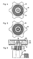
- FIG. 2 shows a variant of the ring disks 2, 3 and 4, with these corresponding rings designated 102, 103 and 104 being another Have bead / groove connection 108, 109.
- the ring disk 103 is substantially wider than the ring disk 102 in accordance with the data to be recorded.
- the washer 104 is only indicated by dashed lines as an indication that it is only provided if necessary.
- FIG. 3 A further variant of this first exemplary embodiment is shown in FIG. 3, namely the ring disks, which are identified here by 202, 203 and 204.
- the annular disks are designed to be open on the side, so that they can be pushed over the screw thread 5 even when the valve 6 is screwed in.
- the width of these radial openings 17, 18 and 19 corresponds to the diameter of the socket of the screw thread 5.
- the ring encompassing the smaller ring is in the opening 17, 18 of the smaller ring, a nose 21 and 22 are provided, the width of which corresponds approximately to the width of the associated radial opening 17, 18.
- the lugs 21 and 22 thus act on the one hand as a kind of anti-rotation of the rings with each other, but on the other hand also as a radial play compensation, namely, as shown in Fig. 3, when the nose 21 extends to the screw thread 5 and the nose 22 to the outer circumferential surface of the washer 202.
- Fig. 3 by the sectional area, different can be used for the washers Materials are used, for example in the case of the washers 202 and 204 certain plastics and in the case of the washer 203 metal, the latter being suitable for recording magnetic codes.
- they can have snap connections, as in the previously described variants, between the mutually facing radial lateral surfaces.
- annular disk 23 is fastened on the free end face of the handwheel 113, in particular with the nut 24 which clamps the handwheel on the valve, wherein this data carrier ring 23 can be a plurality of rings which are snapped into one another or only one , which is combined in combination with other, then correspondingly different, meaningful rings.
- this data carrier ring 23 can be a plurality of rings which are snapped into one another or only one , which is combined in combination with other, then correspondingly different, meaningful rings.
- the free end face of a handwheel is used to arrange a disk ring disk. a corresponding lowering can be provided in this end face, or the disk can simply be placed on the end face.
- the end face of the handwheel 213 is also used for the attachment of a data carrier disk 123.
- the handwheel 213 is shown in plan view, in Fig. 6 in section.
- the disk 123 is in a corresponding axial recess 25 of the handwheel 213 embedded and has no central opening.
- This data carrier disk 123 covers the nut 24 of the handwheel 213, which is accommodated in a corresponding recess 26.
- a further data carrier is embedded as an annular disk 27 for storing a further statement group, this annular disk 27 having to be read, if necessary, via a reading device having a mirror.
- valve 106 has a cylindrical section 28 on the valve housing, over which a band-shaped data carrier ring 29 is placed.
- the code markings 31 are oriented here, for example, in the axial direction.
- a plurality of ring disks can be plugged into one another, a plurality of ring bands can also be arranged next to one another and coupled to one another. For example, they can consist of cylinder parts that can be plugged together.
Landscapes
- Physics & Mathematics (AREA)
- General Physics & Mathematics (AREA)
- Engineering & Computer Science (AREA)
- Theoretical Computer Science (AREA)
- Filling Or Discharging Of Gas Storage Vessels (AREA)
Abstract
Claims (12)
- Dispositif d'étiquetage conçu pour des objets d'une fonction précise, avec des supports de données de préférence de forme circulaire, présentant au moins deux marquages de code de données de catégories d'information différentes étant entendu que les données lisibles (information) des catégories d'information concernent l'objet et/ou sa fonction et son contenu le cas échéant et qu'elles sont coordonnées les unes aux autres et étant entendu aussi que les supports de données coordonnés les uns aux autres sont disposés sur l'objet de sorte à pouvoir en être détachés, mais dont la disposition dans l'espace des uns par rapport aux autres ne peut relativement pas être modifiée, caractérisé par le fait que la disposition correcte relative dans l'espace des supports de données (2, 3, 4, 15, 23, 27 et 29) les uns par rapport aux autres est contraignante.
- Dispositif d'étiquetage conforme à la revendication 1, caractérisé par le fait qu'au moins deux des supports de données coordonnées l'un à l'autre ont une configuration de disque annulaire (2, 3, 4, 102, 103, 104, 202, 203, 204) dont les dimensions radiales intérieures et extérieures harmonisées les unes avec les autres autorisent un emboîtement des disques annulaires, à savoir respectivement un disque annulaire plus petit dans l'orifice intérieur d'un disque plus grand, et par le fait que pour une surface de lecture (12) commune les disques annulaires présentent un marquage de code sur la face axiale ou sur le disque accusant un diamètre supérieur, un marquage sur la surface radiale.
- Dispositif d'étiquetage conforme à la revendication 2, caractérisé par le fait qu'entre les surfaces de l'enveloppe ou qu'entre les surfaces d'alésage radiales des disques annulaires orientées les unes vers les autres, il existe des renflements (8, 108) et des rainures annulaires (9, 109) qui constituent un assemblage à enclenchement empêchant un décalage axial des uns par rapport aux autres.
- Dispositif d'étiquetage conforme à la revendication 2 ou 3, caractérisé par le fait qu'à titre de sécurité anti-jeu et anti-torsion des disques annulaires les uns par rapport aux autres, il existe au moins sur les surfaces de l'enveloppe ou sur les surfaces d'alésage radiales des disques annulaires orientées les unes vers les autres (203, 204), des nez (21, 22) sur un disque qui mordent dans les évidements (17, 18) correspondants de l'autre disque.
- Dispositif d'étiquetage conforme à l'une des revendications précédentes, caractérisé par le fait qu'au moins un des supports de données coordonnés les uns aux autres a la forme d'une bande annulaire de données (29, 15) cylindrique ou conique placée autour d'une section (14, 28) d'une surface d'enveloppe de l'objet, ayant une configuration correspondante ou autour d'une pièce solidement reliée à l'objet, telle qu'une soupape (106) ou qu'un volant (13).
- Dispositif d'étiquetage conforme à la revendication 5, caractérisé par le fait qu'au moins deux bandes annulaires de données coordonnées l'une à l'autre sont disposées l'une à côté de l'autre sur l'objet et qu'elles sont à l'abri d'une torsion réciproque compte tenu des élévations ou des évidements axiaux s'engrenant les uns dans les autres.
- Dispositif d'étiquetage conforme à l'une des revendications précédentes, caractérisé par le fait qu'au moins un support de données (15, 23, 29) comporte un code barres balayable optiquement.
- Dispositif d'étiquetage conforme à l'une des revendications précédentes, caractérisé par le fait qu'au moins un support de données renferme une piste magnétique pour un code magnétique incrusté ou incrustable.
- Dispositif d'étiquetage conforme à l'une des revendications 2 à 8, caractérisé par le fait que les anneaux des supports de données (202, 203, 204) présentent radialement et d'un seul côté une ouverture afin, précisément par cette ouverture (17, 18, 19), de pouvoir coulisser radialement sur une pièce support (6).
- Dispositif d'étiquetage conforme à l'une des revendications précédentes, caractérisé par son utilisation sur un réservoir à gaz (bouteille de gaz), l'objet, étant entendu que les supports de données (2, 3, 4, 15, 27, 29) sont disposés de préférence dans la zone de la soupape de sortie (6, 106) du réservoir à gaz.
- Dispositif d'étiquetage conforme à la revendication 10, caractérisé par le fait que les supports de données sont agencés sur le corps de soupape (6, 106) et/ou sur le volant de la soupape (13, 213).
- Dispositif d'étiquetage conforme à la revendication 11, caractérisé par le fait que respectivement un support de données (27, 123) est disposé sur respectivement une des faces du volant (213) opposées l'une à l'autre.
Applications Claiming Priority (2)
| Application Number | Priority Date | Filing Date | Title |
|---|---|---|---|
| DE3927195 | 1989-08-17 | ||
| DE3927195A DE3927195A1 (de) | 1989-08-17 | 1989-08-17 | Kennzeichnungseinrichtung mit codemarkierungen aufweisenden datentraegern |
Publications (2)
| Publication Number | Publication Date |
|---|---|
| EP0486549A1 EP0486549A1 (fr) | 1992-05-27 |
| EP0486549B1 true EP0486549B1 (fr) | 1993-05-12 |
Family
ID=6387305
Family Applications (1)
| Application Number | Title | Priority Date | Filing Date |
|---|---|---|---|
| EP90911922A Expired - Lifetime EP0486549B1 (fr) | 1989-08-17 | 1990-08-16 | Dispositif d'identification avec supports de donnees presentant des marquages codes |
Country Status (3)
| Country | Link |
|---|---|
| EP (1) | EP0486549B1 (fr) |
| DE (2) | DE3927195A1 (fr) |
| WO (1) | WO1991003027A1 (fr) |
Families Citing this family (3)
| Publication number | Priority date | Publication date | Assignee | Title |
|---|---|---|---|---|
| FR2685519A1 (fr) * | 1991-12-20 | 1993-06-25 | Gemplus Card Int | Systeme pour l'identification de recipients et notamment de bouteilles de gaz. |
| DE4409313C2 (de) * | 1994-03-18 | 2002-01-10 | Messer Griesheim Gmbh | Vorrichtung für die Aufnahme elektronischer Datenträger für Gasflaschen |
| DE19621901C2 (de) * | 1996-05-31 | 2001-12-06 | Bosch Gmbh Robert | Verfahren und Vorrichtung mit Datenträger |
Family Cites Families (3)
| Publication number | Priority date | Publication date | Assignee | Title |
|---|---|---|---|---|
| CH457924A (de) * | 1967-02-09 | 1968-06-15 | Zellweger Uster Ag | Verfahren und Vorrichtung zur Kennzeichnung von Verkaufs- und/oder Lagergegenständen |
| US3711683A (en) * | 1971-01-08 | 1973-01-16 | Monarch Marking Systems Inc | Re-price marking method and record member |
| WO1983004446A1 (fr) * | 1982-06-11 | 1983-12-22 | Management Investment & Technology Co., Ltd. | Procede et dispositif d'entree et de stockage de donnees dans un ordinateur programmable manuellement |
-
1989
- 1989-08-17 DE DE3927195A patent/DE3927195A1/de not_active Withdrawn
-
1990
- 1990-08-16 WO PCT/DE1990/000630 patent/WO1991003027A1/fr not_active Ceased
- 1990-08-16 EP EP90911922A patent/EP0486549B1/fr not_active Expired - Lifetime
- 1990-08-16 DE DE9090911922T patent/DE59001453D1/de not_active Expired - Fee Related
Also Published As
| Publication number | Publication date |
|---|---|
| WO1991003027A1 (fr) | 1991-03-07 |
| EP0486549A1 (fr) | 1992-05-27 |
| DE59001453D1 (de) | 1993-06-17 |
| DE3927195A1 (de) | 1991-02-21 |
Similar Documents
| Publication | Publication Date | Title |
|---|---|---|
| DE2259731A1 (de) | Kodierte aufschrift zur automatischen identifizierung von gegenstaenden | |
| DE102012105654A1 (de) | Spannvorrichtung zum Dehnen eines Gewindebolzens | |
| DE10343405B4 (de) | NMR-Spektrometer mit Greifvorrichtung zur Handhabung einer Probenhülse mit Außennut | |
| DE19746153C2 (de) | Wasserzähler | |
| EP0486549B1 (fr) | Dispositif d'identification avec supports de donnees presentant des marquages codes | |
| DE602004008117T2 (de) | Lagerungseinheit mit identifizierungsmarkierungen | |
| DE4409313A1 (de) | Vorrichtung für die Aufnahme elektronischer Datenträger für Gasflaschen | |
| DE69216741T2 (de) | Spender für flache Gegenstände | |
| DE3506639A1 (de) | Transport- und/oder lagerbehaelter mit datentraeger | |
| DE69804043T2 (de) | Vorrichtung zur visuellen Identifizierung des Zustandes einer Holzstruktur, insbesondere eines Pfosten, nach Qualitätskontrolle | |
| EP3798151B1 (fr) | Bouteille d'échantillon, en particulier bouteille d'échantillon de lait | |
| AT393747B (de) | Kennzeichnungstraeger fuer einen gegenstand | |
| DE19749221C2 (de) | Vorrichtung zum Bestimmen der physikalischen Eigenschaften von Dünger | |
| DE202010014500U1 (de) | Getränkebehälter mit RFID-Transponder | |
| DE102021120578B4 (de) | Probenflasche, insbesondere Milchprobenflasche | |
| DE3904258C2 (fr) | ||
| DE20009787U1 (de) | Anzeigevorrichtung mit mehreren Kontrastbildern | |
| DE2315412A1 (de) | Vorrichtung zum pruefen des dichtkantenabstandes bei lippendichtungsringen | |
| CH721327A1 (de) | Kunststoff-Mehrwegbehälter | |
| DE102012011031A1 (de) | Unterteil für eine Spinnspindel | |
| EP2335826A1 (fr) | Récipient identifiable | |
| DE102022115342A1 (de) | Matrixcode für eine Stirnseite eines zylindrischen Bauteils | |
| DE2355608C3 (de) | Siegel fur einen Kernbrennstoff enthaltenden Gegenstand | |
| DE2028130C3 (de) | Vorrichtung zur Identifizierung von auf einer Spule aufgewickelten Garnen | |
| DE19723797C2 (de) | Probenteiler |
Legal Events
| Date | Code | Title | Description |
|---|---|---|---|
| PUAI | Public reference made under article 153(3) epc to a published international application that has entered the european phase |
Free format text: ORIGINAL CODE: 0009012 |
|
| 17P | Request for examination filed |
Effective date: 19920229 |
|
| AK | Designated contracting states |
Kind code of ref document: A1 Designated state(s): DE DK GB IT LU |
|
| 17Q | First examination report despatched |
Effective date: 19920707 |
|
| GRAA | (expected) grant |
Free format text: ORIGINAL CODE: 0009210 |
|
| AK | Designated contracting states |
Kind code of ref document: B1 Designated state(s): DE DK GB IT LU |
|
| PG25 | Lapsed in a contracting state [announced via postgrant information from national office to epo] |
Ref country code: IT Free format text: LAPSE BECAUSE OF FAILURE TO SUBMIT A TRANSLATION OF THE DESCRIPTION OR TO PAY THE FEE WITHIN THE PRE;WARNING: LAPSES OF ITALIAN PATENTS WITH EFFECTIVE DATE BEFORE 2007 MAY HAVE OCCURRED AT ANY TIME BEFORE 2007. THE CORRECT EFFECTIVE DATE MAY BE DIFFERENT FROM THE ONE RECORDED.SCRIBED TIME-LIMIT Effective date: 19930512 Ref country code: GB Effective date: 19930512 Ref country code: DK Effective date: 19930512 |
|
| REF | Corresponds to: |
Ref document number: 59001453 Country of ref document: DE Date of ref document: 19930617 |
|
| PG25 | Lapsed in a contracting state [announced via postgrant information from national office to epo] |
Ref country code: LU Free format text: LAPSE BECAUSE OF NON-PAYMENT OF DUE FEES Effective date: 19930831 |
|
| GBV | Gb: ep patent (uk) treated as always having been void in accordance with gb section 77(7)/1977 [no translation filed] |
Effective date: 19930512 |
|
| PGFP | Annual fee paid to national office [announced via postgrant information from national office to epo] |
Ref country code: DE Payment date: 19981029 Year of fee payment: 9 |
|
| PG25 | Lapsed in a contracting state [announced via postgrant information from national office to epo] |
Ref country code: DE Free format text: LAPSE BECAUSE OF NON-PAYMENT OF DUE FEES Effective date: 20000601 |
|
| PLBE | No opposition filed within time limit |
Free format text: ORIGINAL CODE: 0009261 |
|
| STAA | Information on the status of an ep patent application or granted ep patent |
Free format text: STATUS: NO OPPOSITION FILED WITHIN TIME LIMIT |