EP0486669B1 - Dispositif de transfert d'objets a contre-courant d'un flux gazeux - Google Patents
Dispositif de transfert d'objets a contre-courant d'un flux gazeux Download PDFInfo
- Publication number
- EP0486669B1 EP0486669B1 EP91911646A EP91911646A EP0486669B1 EP 0486669 B1 EP0486669 B1 EP 0486669B1 EP 91911646 A EP91911646 A EP 91911646A EP 91911646 A EP91911646 A EP 91911646A EP 0486669 B1 EP0486669 B1 EP 0486669B1
- Authority
- EP
- European Patent Office
- Prior art keywords
- tube
- objects
- flow
- bag
- bottles
- Prior art date
- Legal status (The legal status is an assumption and is not a legal conclusion. Google has not performed a legal analysis and makes no representation as to the accuracy of the status listed.)
- Expired - Lifetime
Links
- 239000004033 plastic Substances 0.000 claims description 9
- 229920003023 plastic Polymers 0.000 claims description 9
- 238000004519 manufacturing process Methods 0.000 claims description 7
- 238000004806 packaging method and process Methods 0.000 claims description 6
- 230000005484 gravity Effects 0.000 claims description 3
- 239000007787 solid Substances 0.000 claims description 2
- 239000000463 material Substances 0.000 claims 3
- 238000006073 displacement reaction Methods 0.000 claims 1
- 239000003570 air Substances 0.000 description 15
- 230000004907 flux Effects 0.000 description 8
- 238000009434 installation Methods 0.000 description 7
- 230000003749 cleanliness Effects 0.000 description 6
- 239000002245 particle Substances 0.000 description 6
- 238000007789 sealing Methods 0.000 description 6
- 239000012535 impurity Substances 0.000 description 4
- 239000012080 ambient air Substances 0.000 description 3
- 235000021183 entrée Nutrition 0.000 description 3
- 238000000034 method Methods 0.000 description 3
- 230000032258 transport Effects 0.000 description 3
- 238000005520 cutting process Methods 0.000 description 2
- 238000000605 extraction Methods 0.000 description 2
- 239000002985 plastic film Substances 0.000 description 2
- 229920006255 plastic film Polymers 0.000 description 2
- 238000007493 shaping process Methods 0.000 description 2
- 230000009471 action Effects 0.000 description 1
- 230000001174 ascending effect Effects 0.000 description 1
- 230000001143 conditioned effect Effects 0.000 description 1
- 230000002950 deficient Effects 0.000 description 1
- 239000003814 drug Substances 0.000 description 1
- 239000000428 dust Substances 0.000 description 1
- 230000008030 elimination Effects 0.000 description 1
- 238000003379 elimination reaction Methods 0.000 description 1
- 230000006872 improvement Effects 0.000 description 1
- 238000005192 partition Methods 0.000 description 1
- 239000000825 pharmaceutical preparation Substances 0.000 description 1
- 229940127557 pharmaceutical product Drugs 0.000 description 1
- 238000000926 separation method Methods 0.000 description 1
- 238000003466 welding Methods 0.000 description 1
Images


Classifications
-
- B—PERFORMING OPERATIONS; TRANSPORTING
- B65—CONVEYING; PACKING; STORING; HANDLING THIN OR FILAMENTARY MATERIAL
- B65B—MACHINES, APPARATUS OR DEVICES FOR, OR METHODS OF, PACKAGING ARTICLES OR MATERIALS; UNPACKING
- B65B55/00—Preserving, protecting or purifying packages or package contents in association with packaging
- B65B55/02—Sterilising, e.g. of complete packages
Definitions
- the present invention relates to a device for transferring objects in a gaseous medium with a content of controlled impurities, in particular of plastic bottles intended for the pharmaceutical industry.
- bottles containing air are used which contain only a limited number of impurities.
- the air contained in the bottles intended for the pharmaceutical industry must have a determined level of particulate cleanliness.
- the particulate cleanliness of air or a gas is defined and classified by standard NF-X 44-101.
- the dustiness of a gas is defined by the numerical concentrations of suspended particles whose sizes are greater than defined particle size levels (in general 5 microns and 0.5 microns).
- a dust class limit is established by setting a maximum numerical concentration for each of the particle size levels.
- the NF-X 44-101 standard proposes a simplified procedure defining three classes according to the table below:
- the pharmaceutical industry requires manufacturers to supply bottles containing as pure air as possible and at most class 400,000.
- the manufacturers install the machines in a closed enclosure permanently swept by a laminar flow of air of class 400,000.
- the manufactured bottles are transferred manually into a plastic bag by an operator who enters the enclosure via a airlock, close the bag and transport the bags outside the closed enclosure through the airlock.
- the operator must take great precautions in terms of hygiene and clothing: gloves, blouse or white jumpsuit, that is to say free of loose particles that can adhere to it, shoe covers, hairstyle, mask, etc.
- the object of the invention is to produce objects whose level of cleanliness can be guaranteed, by eliminating human intervention.
- the invention relates to a device according to claim 1.
- the invention also relates to an installation for manufacturing and packaging plastic bottles comprising an enclosure constituting a first medium, in which at least the final manufacturing step is carried out, and a room isolated from the enclosure, constituting the second medium and in which at least the first step of packaging the vials is carried out, and comprising at least one transfer device from the enclosure to the room produced in accordance with the invention.
- the installation further comprises a bag feeding device comprising a plastic film feeding reel, the latter surrounding the lower end of the tube so that its edges overlap along a generatrix of the tube. , a first heat sealing device located opposite said generator being intended to shape the film into a cylinder coaxial with the tube, a second heat sealing device located below the outlet opening of the tube being intended to form the bottom of the bag.
- the installation includes a device for counting the bottles introduced into the bag, and a third heat sealing device located axially beyond the second heat sealing device intended to hermetically seal the bag containing a predetermined number of bottles, and includes a device for separation of the closed bag from said coaxial cylinder.
- Figure 1 is shown schematically an enclosure E constituting a first medium.
- the enclosure E is separated by a partition 2 from a room S constituting a second medium.
- the enclosure E contains an end portion 4 of a machine M intended for manufacturing plastic bottles.
- the end 4 consists at least of the station for ejecting the bottles produced by the machine M.
- the bottles are conveyed by a handling device 6 to a transfer device 8 according to the invention.
- the transfer device 8 crosses the wall 2 in leaktight manner and opens into the room S above a conveyor 10.
- the first medium is a 400,000 class medium and the second medium is 4,000 class.
- FIG 2 there is shown schematically the handling device 6 which is intended to recover the bottles from the extraction station of the machine M to transport them to the top of an inlet orifice 12 of the transfer device 8 .
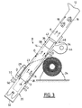
- the transfer device 8 comprises a tube 14 with an internal diameter larger than that of the bottles 16 to transfer.
- the axis of the tube 14 is inclined relative to the vertical.
- the tube 14 has an open, funnel-shaped upper end to constitute the inlet orifice 12 and facilitate the introduction into the tube 14 of the bottles 16 falling from the transfer device 6.
- the tube 14 has an open lower end forming an outlet orifice 18.
- the lower end of the tube 14 enters a plastic bag 20, the mouth of which tightly surrounds the lower end of the tube.
- the bag 20 is made from a plastic film 22 wound on a reel 24.
- the film 20 surrounds the lower part of the tube 14 so that its two longitudinal edges overlap along a generatrix of the tube located in front of a heat sealer 26 which thus conforms the film 20 into a cylinder 28 surrounding the lower end of the tube 14.
- a radial thermal clamp 30 located below the outlet orifice 18 is intended to conform the bottom 32 of the bag.
- the bottom 32 shaped by heat sealing is airtight.
- the tube 14 has a lateral opening 34 pierced in its tubular wall.
- An orientation device 36 is located inside the tube 14.
- the device 36 consists of a sleeve 38 coaxial with the tube 14, the wall of the sleeve being located opposite the opening 34.
- the sleeve 38 has an outside diameter smaller than the inside diameter of the tube 14 so as to delimit between them an annular space 40, the opening 34 opening into the annular space 40.
- the open end of the sleeve 38 located between the opening 34 and the inlet orifice 12 comprises an external radial flange 42 which is fixed to the internal face of the tube 14 and closes the upper end of the annular space 40.
- a device 44 known per se is intended to inject class 4,000 air through the opening 34.
- a class 4,000 and ionized air flow is oriented by the orientation device 36 in an annular flow flowing downward along the internal face of the tube 14 and then along the cylindrical side wall of the bag 20.
- This flow of ionized air will make it possible to avoid the introduction of particles, to avoid the creation of electro-static sites on the surface of the bottles, and possibly to carry particles located on the wall of the bottles coming from the pregnant E.
- the flow of the annular flow is delimited in FIG. 3 by a dotted line 43, the direction of flow being represented by the arrows D.
- the line 43 is located in the extension of the wall of the sleeve 38.
- the wall of the sleeve can extend over a greater length, for example up to the outlet orifice 18 and even beyond.
- the annular flow strikes the bottom 32 of the bag 20 which reflects it and transforms it into a flow central coaxial with the tube and ascending schematically represented by the arrows A, that is to say against the current of the annular flow and surrounded by it.
- the upward flow flows around the axis of the bag 20, crosses the interior space of the sleeve 36 and then flows into the part of the tube 14 located above the flange 42, up to the orifice. input 12 through which it leaves the transfer device 8.
- the bottles 16 carry out their journey between the inlet orifice 12 and the bag 20 against the current of the upward coaxial flow, the impurities which are possibly bonded to the external wall of the bottle 16 being entrained by said upward flow.
- the enclosure E comprises a device known by either filling the enclosure with air of class 400,000 per using filtered laminar flow.
- the enclosure can be in the open air and the handling device 6 can be sealed in a sealed manner and supplied with laminar air flows of class 400,000.
- the bottle is clean. It is then soiled in contact with the air surrounding the demolding and ejection station.
- This air is of class 400,000 (ambient air of the enclosure or of the handling device) limits the pollution of the bottle and facilitates the elimination of impurities in the transfer device according to the invention.
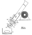
- a second radial sealer 50 is provided, located axially beyond the radial sealer 30 from the outlet 18 of the tube 14.
- a cutting device 53 is installed between the radial welders.
- a bottle counting device controls, when the bag 20 contains a predetermined number of bottles (see FIG. 4), the sealer 50 which seals the bag 20 by sealing 52, the sealer 30 simultaneously forming the bottom 32a of the next bag.
- the cutting device 53 detaches the bag 20 which falls on the conveyor 10.
- the conveyor 10 transports the bag over a bagging device located in room S, that is to say in ambient air of class 4.000 (see FIG. 5).
- the bagging device comprises a cylindrical tube 60 into which the bags 20 fall.
- the lower end of the tube 60 is provided with a bagging device similar to that described with reference to FIG. 4.
- the bag 20 comprising the predetermined number of bottles 16 is wrapped in a second bag 62 whose ambient air is of class 4,000.
- This double protection provides additional security when handling and transporting the bottles thus conditioned.
- the transfer device 8 described above receiving flasks located in an air of class 400,000 which are transferred into a medium of class 4,000, makes it possible to guarantee a level of cleanliness of class 400,000 which is an improvement compared to flasks of which only the manufacturing process can be guaranteed.
Landscapes
- Mechanical Engineering (AREA)
- Engineering & Computer Science (AREA)
- Basic Packing Technique (AREA)
- Devices And Processes Conducted In The Presence Of Fluids And Solid Particles (AREA)
- Fuel Cell (AREA)
- Container Filling Or Packaging Operations (AREA)
- Sheets, Magazines, And Separation Thereof (AREA)
- Manipulator (AREA)
- Supply Of Fluid Materials To The Packaging Location (AREA)
- Tunnel Furnaces (AREA)
- Container, Conveyance, Adherence, Positioning, Of Wafer (AREA)
- Sampling And Sample Adjustment (AREA)
- Separation By Low-Temperature Treatments (AREA)
Applications Claiming Priority (2)
| Application Number | Priority Date | Filing Date | Title |
|---|---|---|---|
| FR9007363 | 1990-06-13 | ||
| FR909007363A FR2663294B1 (fr) | 1990-06-13 | 1990-06-13 | Dispositif de transfert d'objets a contre-courant d'un flux gazeux. |
Publications (2)
| Publication Number | Publication Date |
|---|---|
| EP0486669A1 EP0486669A1 (fr) | 1992-05-27 |
| EP0486669B1 true EP0486669B1 (fr) | 1994-03-30 |
Family
ID=9397562
Family Applications (1)
| Application Number | Title | Priority Date | Filing Date |
|---|---|---|---|
| EP91911646A Expired - Lifetime EP0486669B1 (fr) | 1990-06-13 | 1991-06-12 | Dispositif de transfert d'objets a contre-courant d'un flux gazeux |
Country Status (9)
| Country | Link |
|---|---|
| US (1) | US5255496A (da) |
| EP (1) | EP0486669B1 (da) |
| AT (1) | ATE103554T1 (da) |
| DE (1) | DE69101538T2 (da) |
| DK (1) | DK0486669T3 (da) |
| ES (1) | ES2054498T3 (da) |
| FR (1) | FR2663294B1 (da) |
| IE (1) | IE64958B1 (da) |
| WO (1) | WO1991019646A1 (da) |
Families Citing this family (3)
| Publication number | Priority date | Publication date | Assignee | Title |
|---|---|---|---|---|
| AU5094200A (en) * | 1999-06-05 | 2000-12-28 | Cambridge Consultants Limited | Liquid feed bottle |
| US6588184B2 (en) * | 2001-11-29 | 2003-07-08 | Harry Bussey, Jr. | Bag forming and filling machine |
| US20100095638A1 (en) * | 2008-09-25 | 2010-04-22 | Zakowski Joseph W | Vacuum sealing appliance |
Family Cites Families (8)
| Publication number | Priority date | Publication date | Assignee | Title |
|---|---|---|---|---|
| US3040490A (en) * | 1960-05-31 | 1962-06-26 | Triangle Package Machinery Co | Apparatus and method for making, filling, and sealing containers |
| US3482373A (en) * | 1967-11-06 | 1969-12-09 | Packaging Frontiers Inc | Packaging |
| US3681892A (en) * | 1970-08-26 | 1972-08-08 | Hayssen Mfg Co | Packaging machine |
| SE437136B (sv) * | 1984-03-08 | 1985-02-11 | Tetra Pak Int | Sett och anordning vid tillverkning och fyllning av forpackningsbehallare |
| US4522581A (en) * | 1984-09-07 | 1985-06-11 | Husky Injection Molding Systems Ltd. | System for handling partly finished workpieces |
| DE3522996A1 (de) * | 1985-06-27 | 1987-01-08 | Kolbus Gmbh & Co Kg | Verfahren zur abgrenzung steriler raeume gegen austreten von toxischen sterilisationsmitteln oder eindringen von mikroorganismen, vorzugsweise in anwendung fuer fuellmaschinen, und vorrichtung zur durchfuehrung des verfahrens |
| AU633806B2 (en) * | 1987-10-30 | 1993-02-11 | Olivier Desjonqueres | Device for processing products under controlled atmosphere and temperature, in particular foodstuffs |
| JP2698929B2 (ja) * | 1989-04-10 | 1998-01-19 | 四国化工機株式会社 | 包装機械の充填装置における洗浄装置 |
-
1990
- 1990-06-13 FR FR909007363A patent/FR2663294B1/fr not_active Expired - Fee Related
-
1991
- 1991-06-12 ES ES91911646T patent/ES2054498T3/es not_active Expired - Lifetime
- 1991-06-12 WO PCT/FR1991/000471 patent/WO1991019646A1/fr not_active Ceased
- 1991-06-12 EP EP91911646A patent/EP0486669B1/fr not_active Expired - Lifetime
- 1991-06-12 AT AT91911646T patent/ATE103554T1/de not_active IP Right Cessation
- 1991-06-12 US US07/829,053 patent/US5255496A/en not_active Expired - Fee Related
- 1991-06-12 DE DE69101538T patent/DE69101538T2/de not_active Expired - Fee Related
- 1991-06-12 DK DK91911646.7T patent/DK0486669T3/da active
- 1991-06-13 IE IE202091A patent/IE64958B1/en not_active IP Right Cessation
Also Published As
| Publication number | Publication date |
|---|---|
| US5255496A (en) | 1993-10-26 |
| IE64958B1 (en) | 1995-09-20 |
| FR2663294A1 (fr) | 1991-12-20 |
| EP0486669A1 (fr) | 1992-05-27 |
| FR2663294B1 (fr) | 1994-06-10 |
| ES2054498T3 (es) | 1994-08-01 |
| WO1991019646A1 (fr) | 1991-12-26 |
| DE69101538D1 (de) | 1994-05-05 |
| ATE103554T1 (de) | 1994-04-15 |
| IE912020A1 (en) | 1991-12-18 |
| DK0486669T3 (da) | 1994-05-02 |
| DE69101538T2 (de) | 1994-08-25 |
Similar Documents
| Publication | Publication Date | Title |
|---|---|---|
| US7523596B2 (en) | Method for packaging of phials in a sterile environment, and apparatus for carrying out the aforesaid method | |
| US3942301A (en) | Apparatus for producing low-oxygen content packages | |
| CN101137546B (zh) | 带有口袋升降装置的口袋成形、填装和封口机器及口袋成形、填装和封口的方法 | |
| KR100911955B1 (ko) | 고순도 물품의 제조 또는 처리 방법 및 고순도 물품의 처리 장치 | |
| KR102414349B1 (ko) | 멸균 벌크 재료를 아이솔레이터로 운반 및 이송시키기 위한 방법 및 컨테이너 | |
| US7827770B2 (en) | Method for the operation of a package emptying station | |
| TW201202018A (en) | Aseptic filling system | |
| JPH08509943A (ja) | シートチューブのヒートシール領域においてシートチューブの内面を無塵に保持するための装置を備えたチューブ袋包装機 | |
| US3061165A (en) | Lined container package | |
| JPH06247402A (ja) | 袋状容器充填方法および袋状容器充填装置 | |
| EP1077176B1 (en) | Bagging and packaging machine capable of sufficiently filling an inert gas into bags | |
| EP0486669B1 (fr) | Dispositif de transfert d'objets a contre-courant d'un flux gazeux | |
| US5097649A (en) | Packaging machine | |
| AU2004314960B2 (en) | Method and device for producing and filling containers | |
| EP4061562B1 (fr) | Module de fourniture de poudre de fabrication additive permettant le rempotage de poudre sous atmosphere inerte | |
| EP4267356A1 (fr) | Dispositif et procede de manipulation de poudres volatiles | |
| JPS6238220B2 (da) | ||
| EP1440887B1 (en) | Method and apparatus for vacuum and/or protective atmosphere packaging | |
| US20250042074A1 (en) | Parison directional canopy for a blow/fill/seal machine | |
| JP4550689B2 (ja) | 縦形製袋充填包装機 | |
| JPH11180417A (ja) | 包装装置 | |
| EP1851118A1 (fr) | Procede et installation de conditionnement en poche souple de produits liquides. | |
| JPH085466B2 (ja) | シール装置 | |
| JP4302860B2 (ja) | 充填装置 | |
| SU1756206A1 (ru) | Способ упаковки сыпучих продуктов в тару из эластичных материалов и устройство дл его осуществлени |
Legal Events
| Date | Code | Title | Description |
|---|---|---|---|
| PUAI | Public reference made under article 153(3) epc to a published international application that has entered the european phase |
Free format text: ORIGINAL CODE: 0009012 |
|
| AK | Designated contracting states |
Kind code of ref document: A1 Designated state(s): AT BE CH DE DK ES FR GB GR IT LI LU NL SE |
|
| 17P | Request for examination filed |
Effective date: 19920612 |
|
| 17Q | First examination report despatched |
Effective date: 19930524 |
|
| GRAA | (expected) grant |
Free format text: ORIGINAL CODE: 0009210 |
|
| AK | Designated contracting states |
Kind code of ref document: B1 Designated state(s): AT BE CH DE DK ES FR GB GR IT LI LU NL SE |
|
| REF | Corresponds to: |
Ref document number: 103554 Country of ref document: AT Date of ref document: 19940415 Kind code of ref document: T |
|
| REG | Reference to a national code |
Ref country code: DK Ref legal event code: T3 |
|
| REF | Corresponds to: |
Ref document number: 69101538 Country of ref document: DE Date of ref document: 19940505 |
|
| GBT | Gb: translation of ep patent filed (gb section 77(6)(a)/1977) |
Effective date: 19940421 |
|
| ITF | It: translation for a ep patent filed | ||
| EPTA | Lu: last paid annual fee | ||
| REG | Reference to a national code |
Ref country code: ES Ref legal event code: FG2A Ref document number: 2054498 Country of ref document: ES Kind code of ref document: T3 |
|
| REG | Reference to a national code |
Ref country code: GR Ref legal event code: FG4A Free format text: 3012372 |
|
| EAL | Se: european patent in force in sweden |
Ref document number: 91911646.7 |
|
| PLBE | No opposition filed within time limit |
Free format text: ORIGINAL CODE: 0009261 |
|
| STAA | Information on the status of an ep patent application or granted ep patent |
Free format text: STATUS: NO OPPOSITION FILED WITHIN TIME LIMIT |
|
| 26N | No opposition filed | ||
| PGFP | Annual fee paid to national office [announced via postgrant information from national office to epo] |
Ref country code: FR Payment date: 19990506 Year of fee payment: 9 |
|
| PGFP | Annual fee paid to national office [announced via postgrant information from national office to epo] |
Ref country code: DK Payment date: 19990511 Year of fee payment: 9 |
|
| PGFP | Annual fee paid to national office [announced via postgrant information from national office to epo] |
Ref country code: AT Payment date: 19990512 Year of fee payment: 9 |
|
| PGFP | Annual fee paid to national office [announced via postgrant information from national office to epo] |
Ref country code: SE Payment date: 19990517 Year of fee payment: 9 Ref country code: GB Payment date: 19990517 Year of fee payment: 9 |
|
| PGFP | Annual fee paid to national office [announced via postgrant information from national office to epo] |
Ref country code: CH Payment date: 19990519 Year of fee payment: 9 |
|
| PGFP | Annual fee paid to national office [announced via postgrant information from national office to epo] |
Ref country code: DE Payment date: 19990526 Year of fee payment: 9 |
|
| PGFP | Annual fee paid to national office [announced via postgrant information from national office to epo] |
Ref country code: NL Payment date: 19990531 Year of fee payment: 9 |
|
| PGFP | Annual fee paid to national office [announced via postgrant information from national office to epo] |
Ref country code: ES Payment date: 19990604 Year of fee payment: 9 |
|
| PGFP | Annual fee paid to national office [announced via postgrant information from national office to epo] |
Ref country code: BE Payment date: 19990607 Year of fee payment: 9 |
|
| PGFP | Annual fee paid to national office [announced via postgrant information from national office to epo] |
Ref country code: LU Payment date: 19990617 Year of fee payment: 9 |
|
| PGFP | Annual fee paid to national office [announced via postgrant information from national office to epo] |
Ref country code: GR Payment date: 19990621 Year of fee payment: 9 |
|
| PG25 | Lapsed in a contracting state [announced via postgrant information from national office to epo] |
Ref country code: LU Free format text: LAPSE BECAUSE OF NON-PAYMENT OF DUE FEES Effective date: 20000612 Ref country code: GB Free format text: LAPSE BECAUSE OF NON-PAYMENT OF DUE FEES Effective date: 20000612 Ref country code: DK Free format text: LAPSE BECAUSE OF NON-PAYMENT OF DUE FEES Effective date: 20000612 Ref country code: AT Free format text: LAPSE BECAUSE OF NON-PAYMENT OF DUE FEES Effective date: 20000612 |
|
| PG25 | Lapsed in a contracting state [announced via postgrant information from national office to epo] |
Ref country code: SE Free format text: LAPSE BECAUSE OF NON-PAYMENT OF DUE FEES Effective date: 20000613 Ref country code: ES Free format text: THE PATENT HAS BEEN ANNULLED BY A DECISION OF A NATIONAL AUTHORITY Effective date: 20000613 |
|
| PG25 | Lapsed in a contracting state [announced via postgrant information from national office to epo] |
Ref country code: LI Free format text: LAPSE BECAUSE OF NON-PAYMENT OF DUE FEES Effective date: 20000630 Ref country code: GR Free format text: LAPSE BECAUSE OF NON-PAYMENT OF DUE FEES Effective date: 20000630 Ref country code: CH Free format text: LAPSE BECAUSE OF NON-PAYMENT OF DUE FEES Effective date: 20000630 Ref country code: BE Free format text: LAPSE BECAUSE OF NON-PAYMENT OF DUE FEES Effective date: 20000630 |
|
| BERE | Be: lapsed |
Owner name: KERPLAS SNC Effective date: 20000630 |
|
| PG25 | Lapsed in a contracting state [announced via postgrant information from national office to epo] |
Ref country code: NL Free format text: LAPSE BECAUSE OF NON-PAYMENT OF DUE FEES Effective date: 20010101 |
|
| GBPC | Gb: european patent ceased through non-payment of renewal fee |
Effective date: 20000612 |
|
| REG | Reference to a national code |
Ref country code: CH Ref legal event code: PL |
|
| EUG | Se: european patent has lapsed |
Ref document number: 91911646.7 |
|
| REG | Reference to a national code |
Ref country code: DK Ref legal event code: EBP |
|
| PG25 | Lapsed in a contracting state [announced via postgrant information from national office to epo] |
Ref country code: FR Free format text: LAPSE BECAUSE OF NON-PAYMENT OF DUE FEES Effective date: 20010228 |
|
| NLV4 | Nl: lapsed or anulled due to non-payment of the annual fee |
Effective date: 20010101 |
|
| REG | Reference to a national code |
Ref country code: FR Ref legal event code: ST |
|
| PG25 | Lapsed in a contracting state [announced via postgrant information from national office to epo] |
Ref country code: DE Free format text: LAPSE BECAUSE OF NON-PAYMENT OF DUE FEES Effective date: 20010403 |
|
| REG | Reference to a national code |
Ref country code: ES Ref legal event code: FD2A Effective date: 20020204 |
|
| PG25 | Lapsed in a contracting state [announced via postgrant information from national office to epo] |
Ref country code: IT Free format text: LAPSE BECAUSE OF NON-PAYMENT OF DUE FEES;WARNING: LAPSES OF ITALIAN PATENTS WITH EFFECTIVE DATE BEFORE 2007 MAY HAVE OCCURRED AT ANY TIME BEFORE 2007. THE CORRECT EFFECTIVE DATE MAY BE DIFFERENT FROM THE ONE RECORDED. Effective date: 20050612 |