EP0486719A1 - Einzelkopfvorrichtung zum Entstapeln alternierender Gegenstände von einem Stapel der Gegenstände - Google Patents
Einzelkopfvorrichtung zum Entstapeln alternierender Gegenstände von einem Stapel der Gegenstände Download PDFInfo
- Publication number
- EP0486719A1 EP0486719A1 EP90122222A EP90122222A EP0486719A1 EP 0486719 A1 EP0486719 A1 EP 0486719A1 EP 90122222 A EP90122222 A EP 90122222A EP 90122222 A EP90122222 A EP 90122222A EP 0486719 A1 EP0486719 A1 EP 0486719A1
- Authority
- EP
- European Patent Office
- Prior art keywords
- stack
- suction devices
- articles
- pins
- uppermost
- Prior art date
- Legal status (The legal status is an assumption and is not a legal conclusion. Google has not performed a legal analysis and makes no representation as to the accuracy of the status listed.)
- Withdrawn
Links
- 238000000034 method Methods 0.000 claims abstract description 11
- 239000000919 ceramic Substances 0.000 claims description 29
- 239000000463 material Substances 0.000 claims description 8
- 239000012636 effector Substances 0.000 abstract description 4
- 230000008569 process Effects 0.000 description 7
- 238000000926 separation method Methods 0.000 description 4
- 238000001465 metallisation Methods 0.000 description 3
- 230000009471 action Effects 0.000 description 2
- 238000004519 manufacturing process Methods 0.000 description 2
- 230000007246 mechanism Effects 0.000 description 2
- 239000000758 substrate Substances 0.000 description 2
- 238000000151 deposition Methods 0.000 description 1
- 238000011143 downstream manufacturing Methods 0.000 description 1
- 230000000694 effects Effects 0.000 description 1
- 230000005611 electricity Effects 0.000 description 1
- 230000005484 gravity Effects 0.000 description 1
- 230000002093 peripheral effect Effects 0.000 description 1
- 230000003068 static effect Effects 0.000 description 1
- 239000000126 substance Substances 0.000 description 1
- 230000037303 wrinkles Effects 0.000 description 1
Images

Classifications
-
- B—PERFORMING OPERATIONS; TRANSPORTING
- B65—CONVEYING; PACKING; STORING; HANDLING THIN OR FILAMENTARY MATERIAL
- B65H—HANDLING THIN OR FILAMENTARY MATERIAL, e.g. SHEETS, WEBS, CABLES
- B65H3/00—Separating articles from piles
- B65H3/08—Separating articles from piles using pneumatic force
- B65H3/0808—Suction grippers
- B65H3/0816—Suction grippers separating from the top of pile
-
- B—PERFORMING OPERATIONS; TRANSPORTING
- B65—CONVEYING; PACKING; STORING; HANDLING THIN OR FILAMENTARY MATERIAL
- B65H—HANDLING THIN OR FILAMENTARY MATERIAL, e.g. SHEETS, WEBS, CABLES
- B65H3/00—Separating articles from piles
- B65H3/46—Supplementary devices or measures to assist separation or prevent double feed
- B65H3/54—Pressing or holding devices
-
- B—PERFORMING OPERATIONS; TRANSPORTING
- B65—CONVEYING; PACKING; STORING; HANDLING THIN OR FILAMENTARY MATERIAL
- B65H—HANDLING THIN OR FILAMENTARY MATERIAL, e.g. SHEETS, WEBS, CABLES
- B65H2701/00—Handled material; Storage means
- B65H2701/10—Handled articles or webs
- B65H2701/18—Form of handled article or web
- B65H2701/182—Piled package
- B65H2701/1826—Arrangement of sheets
- B65H2701/18264—Pile of alternate articles of different properties, e.g. pile of working sheets with intermediate sheet between each working sheet
Definitions
- the present invention relates generally to the vacuum removal of articles from a vertical stack of the articles, or at some angle to the vertical, and particularly to a single unit device that consecutively and sequentially removes interleaved, alternating first and second articles from a stack of the articles.
- the invention has particular utility in separating green ceramic cards from sheets of paper employed to separate the cards from each other, though the invention is not limited thereto.
- Green ceramic cards are used in a co-fired multi-layer process to manufacture interconnect devices for integrated circuit chips. In making such devices, several layers of the green cards are placed together, aligned, laminated, and then cut into small squares or rectangular shapes, each shape providing a substrate package and carrier for an integrated chip after the carrier is fired and cured.
- the cards are preferably stacked with interleaved sheets of paper to prevent the transfer of any substance from one card, such as metallization, to an adjacent card. Further, if the cards and paper are stacked in an inclined container, the paper has smooth surfaces that assist the cards, which are abrasive, to slide into the lowermost position in the container, thereby aligning the cards and paper in the container. Before the cards can be used in making the interconnects discussed above, the paper sheets and cards must be separated from each other.
- Green ceramic cards are also fragile and abrasive, the material of the cards being easily broken and torn. Manual handling and separation of the paper sheets and cards without tearing the cards is difficult, and personnel handling the cards must wear gloves. Gloves are also required to prevent fingerprints in locations where metallization of the card (substrate) surface occurs in the process of providing the card with circuit leads.
- the papers can be deposited in a stack or pile of the same while the cards can be "singulated" for further downstream processing.
- a typical removal rate cycle for one card in the present invention is five seconds.
- a further objective of the invention is to use plain sheets of paper as separators, without any slots or holes provided in the sheets, or any other feature that would add to the cost of the sheets and therefore to the cost of the overall process.
- a single head or end effector device provided with a plurality of suction cups and spring loaded hold-down pins that engage the uppermost card or paper sheet of a vertical stack of the cards and sheets.
- the head removes the cards and sheets sequentially, i.e., first one and then the other, from the stack and deposits them at respective locations.
- a U.S. patent representative of this art is No. 3,826,485 to Shindo. Shindo employees two suction devices individually vertically translatable in combination with an intermediate holddown pin. Initially, one of the suction devices engages the uppermost sheet near one edge of a stack of sheets, the suction device being activated to lift the edge of the uppermost sheet. This allows air to enter between the uppermost and next adjacent sheet to break initial attraction between the two sheets. A second suction device engaging the sheet is next lifted, with the holddown pin, to complete removal of the sheet from the stack.
- a lifting head structure employed to separate green ceramic sheets and interleaved paper separators is shown in U. S. patent to Buchmann et al.
- a box-like structure is provided with a peripheral, vacuum creating lip.
- the lip is employed to engage the periphery of an uncured green ceramic sheet or paper separator.
- a vacuum is also created in the center of the box such that the sheet or paper separator functions as a diaphragm across the width of the box.
- Such a head requires that it be able to determine which of the items (ceramic sheet or paper separator) the head is engaging.
- separate ceramic and paper sheet sensor pins are provided at spaced apart locations on the head, and the ceramic sheets and paper separators provided with holes corresponding to the locations of the two sensor pins. The head does not provide means to maintain the uppermost paper sheet in contact with the next ceramic sheet so that the paper can be partially lifted, and to holddown the paper sheet when the uppermost item is a ceramic card.
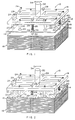
- a single end effector assembly 10 hereinafter referred to as a “head” or “lifting head” is shown somewhat schematically for separating two different alternate items 12 and 14 of flexible material by removing them from a stack 16 of the items and for transporting them to separate respective locations 17 and 18 (Fig. 3) of the alternate items.
- the head is particularly suitable for lifting and separating flexible, fragile blanks or cards from paper sheets separating the blanks or cards.
- Head 10 includes a rigid plate 19 that supports a plurality of suction cups 20 and a plurality of spring-loaded, translatable pins 22. Portions of the plate can be removed (as shown) to decrease its mass and thereby increase its ability to be moved in a rapid manner.
- Hoses 24, only partially shown in Figs. 1 and 2 connect suction cups 20 to a source of vacuum or suction (not shown).
- Coil springs 26 are shown disposed on the shanks of pins 22 and located between the lower surface of plate 19 and shoulder means 28 provided on the shanks at a location between the plate and the end of each pin.
- the vertical location of each shoulder is such that the lower end of the pins can extend below uppermost sheet 12 of stack 16 to the next adjacent sheet 14 in the manner shown in Fig. 1.
- the upper end of each pin 22 is provided with a shoulder or cap 29 to retain the pin in plate 19.
- Cups 20 are connected to the hoses and are supported on the underside of plate 19 by respective hollow connectors 30 suitably mounted in or to the plate.
- the head assembly is secured to the end of a shaft or post 32, that, in turn, is suitably mounted on overhead, horizontal conveying means, diagrammatically represented by horizontal line 34 in Fig. 1 and 2.
- Shaft 32 is vertically translatable by a suitable actuator (not shown) so that head 10 can be raised to a first, rest position over stack 16 and lowered to a second, pick-up position over the stack.
- head 10 is shown in the second position over stack 16.
- the lateral locations of cups 20 on plate 19 are such that they engage the periphery of the uppermost item in stack 16 when the head is lowered to its second position.
- the vertical level of all cups is the same such that they evenly engage the uppermost item 12 having slots 36.
- head 10 In the lowered, second position, head 10 is ready to lift the uppermost item 12 in stack 16. At least a partial vacuum is drawn through cups 20, via connectors 30 and connecting hoses 24, to provide a lifting force to the edges of item 12. The edges lift first, thereby allowing air to enter between the edges of the uppermost and next adjacent item 14. The flow of such air assists the separating process before the uppermost item fully separates from the next item.
- the item 12 is drawn to cups 20, as shown in Fig. 1, while the springs 26 of pins 22 maintain the pins in engagement with the upper surface of the next item 14. In this manner, any remaining electrostatic or other attraction between 12 and 14 is overcome by the force of pins bearing against item 14 and acting against the lifting force exerted when head 10 is lifted.
- Item 12 is thereby available to be removed from stack 16 and transferred to a location 17 (Fig. 3) by head 10 and horizontal conveying means 34.
- the head is raised by its actuator, operating on shaft or post 32, taking with it uppermost item 12.
- Horizontal conveying means then laterally translates the head to the location of 17 or 18 chosen for receiving items 12. Item 12 is released to its chosen location by removing the vacuum or suction from cups 20.
- a non-slotted, flexible item 14 such as a paper separator, is now the uppermost item in the stack. This is shown in Fig. 2 of the drawing.
- Horizontal conveying means 34 returns and aligns head 10 to a first position over stack 16, and the actuator of shaft 32 lowers the head to the second, pick-up position over the stack. The head is now ready to remove the uppermost item 14 from the stack.
- pins 22 holding uppermost item 14 against the next, slotted item 12, at the locations of the pins, as the suction effected through cups 20 pulls those edge portions of separator 14 immediately below the cups to the cups.
- Fig. 2 in which the pins pucker edge portions of 14 at the locations of the pins, and thereby allow air to enter between 14 and 12. This begins the process of separating the sheet from the card.
- the pins will travel to their full extent by action of springs 26 to holddown item 14 before the pins raise with the head.
- the pins in combination with the suction cups, maintain the pucker in item 14 so that air continues to flow and travel from four sides towards the central area between the uppermost and next adjacent item in stack 16 to overcome any remaining attraction between the two items.
- This sequence of operations is repeated for rapid effective separation and removal of items 12 and 14 of stack 16 until removal of the entire stack is completed.
- This sequence of operation is preferably effected by the commands of suitable computer (not shown) connected and programmed to control the actuator of post 32, conveyor 34 and the source of vacuum that creates the suction for cups 20.
- the head 10 of the invention can function in a perfectly vertical manner, as shown in Figs. 1 and 2 of the drawings, or in an inclined manner, as shown in Fig. 3.
- Inclined cassettes or holders 40 and 42 are preferable in the present invention because of their ability to align stacks of items, using the force of gravity acting upon the incline. This is particularly suitable for stacking alternating green ceramic cards and paper separators, as shown diagrammatically by stack 16 in Fig. 3.
- the use of paper separators are advantageous in separating the cards from the separators, as the separators serve well the holddown function described above in connection with Fig 2. Paper separators are also useful, as explained earlier, in preventing the transfer of any metallization on the surface of one card to that of the next adjacent card. In using inclined cassettes, the paper also assists in aligning the paper and cards, as the cards slide easily to the lower side of the cassette and lodge in the lower corners of the cassette.
- center stack 16 is contained in a cassette 40.
- Lifting head 10 is inclined in the same manner as the cassette so that it can function to separate and relocate the cards and papers, as described above.
- each of the cards 12 is transported to and disposed on carrier means 44, located to the left of center stack 16 and in a horizontal plane, while paper separators 14 are transported to and collected in pile 18 in inclined cassette 42, located to the right of center stack 16.
- the above computer orders the operation of the actuators for head 10 and conveyor 34 to alternately stack the papers in cassette 42 and dispose each card on 44 in the manner described above.
- Carrier 44 receives each card and is singularly moved by cylinder 45 to a station (not shown) for further processing of the card. This occurs while each paper item 14 is being transported to cassette 42. Hence, when head 10 returns to 44, 44 will be empty and ready to receive the next card.
- carrier 44 Since carrier 44 is located in a horizontal plane, it is preferable that head 10 release item 12 in a vertical manner, as opposed to the inclined manner of releasing item 14.
- post 32 can be suitably articulated to a vertical position, as shown in phantom in Fig. 3, when it is translated to the left to carry item 12 to carrier 44.
- the head When the head is returned to center cassette 40, it is returned to its inclined position.
- head 10 of the invention a single end effector is employed to consecutively alternately remove both slotted items 12 and non-slotted items 14 from a single stack of the items.
- the head does this rapidly and without tearing the items.
- head 10 can also be used to sequentially remove items from the stack, i.e., if the stack is composed of unslotted paper sheets capable of being puckered by pins 22 and cups 20, head 10 can remove such sheets in a rapid, one-by-one fashion.
Landscapes
- Engineering & Computer Science (AREA)
- Mechanical Engineering (AREA)
- Sheets, Magazines, And Separation Thereof (AREA)
Applications Claiming Priority (1)
| Application Number | Priority Date | Filing Date | Title |
|---|---|---|---|
| US07/386,622 US5048811A (en) | 1989-07-31 | 1989-07-31 | Single head device for removing alternate articles from a stack of the articles |
Publications (1)
| Publication Number | Publication Date |
|---|---|
| EP0486719A1 true EP0486719A1 (de) | 1992-05-27 |
Family
ID=23526371
Family Applications (1)
| Application Number | Title | Priority Date | Filing Date |
|---|---|---|---|
| EP90122222A Withdrawn EP0486719A1 (de) | 1989-07-31 | 1990-11-20 | Einzelkopfvorrichtung zum Entstapeln alternierender Gegenstände von einem Stapel der Gegenstände |
Country Status (2)
| Country | Link |
|---|---|
| US (1) | US5048811A (de) |
| EP (1) | EP0486719A1 (de) |
Cited By (6)
| Publication number | Priority date | Publication date | Assignee | Title |
|---|---|---|---|---|
| EP0744363A3 (de) * | 1995-05-18 | 1997-11-05 | G.D. S.p.A. | Verfahren zum Herausziehen von dazwischenliegenden flachen Trägern für Produktstapel |
| EP1493697A1 (de) * | 2003-07-03 | 2005-01-05 | Heidelberger Druckmaschinen Aktiengesellschaft | Verfahren und Vorrichtung zum Anheben von einzelnen flächigen Objekten, insbesondere von zu belichtenden Druckplatten |
| EP1582486A1 (de) * | 2004-03-31 | 2005-10-05 | Mercandia Industries A/S | Saugkopfeinrichtung zum Heben des obersten blattes eines Stapels von Furnierblättern, und Vorrichtung zum Laminieren von furnierten Brettern |
| CN108927466A (zh) * | 2017-05-24 | 2018-12-04 | 株式会社新韩产业 | 空板分离装置 |
| FR3129384A1 (fr) | 2021-11-25 | 2023-05-26 | Psa Automobiles Sa | Outil de préhension d’un article parmi une pile formée par une pluralité d’articles empilés les uns sur les autres |
| US11667042B2 (en) | 2021-07-15 | 2023-06-06 | Southwest Research Institute | Retainer apparatus for movement of articles |
Families Citing this family (30)
| Publication number | Priority date | Publication date | Assignee | Title |
|---|---|---|---|---|
| US5257776A (en) * | 1990-01-12 | 1993-11-02 | Fuji Photo Film Co., Ltd. | Device for feeding sheets having a detecting means for detecting misfeeds |
| DE4001053A1 (de) * | 1990-01-16 | 1991-07-18 | Focke & Co | Vorrichtung zum abheben von (zwischen-)lagen gestapelter gegenstaende |
| US5290134A (en) * | 1991-12-03 | 1994-03-01 | Advantest Corporation | Pick and place for automatic test handler |
| DE69416911T2 (de) * | 1993-08-19 | 1999-07-08 | Amada Co., Ltd., Isehara, Kanagawa | Entstapelvorrichtung für plattenförmiges Gut |
| JPH07157117A (ja) * | 1993-12-08 | 1995-06-20 | Fuji Photo Film Co Ltd | 板状体または箱体の真空チャック装置 |
| US5447299A (en) * | 1994-02-04 | 1995-09-05 | Riverwood International Corporation | Divider sheet for stacked products and method of supplying planar articles |
| US5471176A (en) * | 1994-06-07 | 1995-11-28 | Quantum Corporation | Glitchless frequency-adjustable ring oscillator |
| US5676364A (en) * | 1994-08-19 | 1997-10-14 | Amada Company, Limited | Plate material separating apparatus |
| DE4435921A1 (de) * | 1994-10-07 | 1996-04-11 | Giesecke & Devrient Gmbh | Vorrichtung und Verfahren zur Vereinzelung von in einem Kartenstapel vorliegenden Karten |
| US5564894A (en) * | 1995-04-06 | 1996-10-15 | Riverwood International Corporation | Article selection and delivery method and apparatus |
| US5818508A (en) * | 1995-10-06 | 1998-10-06 | Gerber Systems Corporation | Imaging device and media handling apparatus |
| US6113346A (en) | 1996-07-31 | 2000-09-05 | Agfa Corporation | Method for loading and unloading a supply of plates in an automated plate handler |
| US6345818B1 (en) * | 1998-10-26 | 2002-02-12 | Fanuc Robotics North America Inc. | Robotic manipulator having a gripping tool assembly |
| JP3365336B2 (ja) * | 1999-04-15 | 2003-01-08 | 株式会社村田製作所 | 積層セラミック電子部品の製造方法 |
| DE10144048B4 (de) * | 2001-09-07 | 2012-09-20 | Leica Mikrosysteme Gmbh | Vorrichtung und Verfahren zum Handhaben von Deckgläsern für Objektträger |
| JP4761341B2 (ja) * | 2002-11-21 | 2011-08-31 | 株式会社ブリヂストン | 吸着搬送装置 |
| WO2004066279A1 (en) * | 2003-01-20 | 2004-08-05 | Sae Magnetics (H.K.) Ltd. | System and method for manufacture of hard disc drive arm and bonding of magnetic head to suspension on a drive arm. |
| DK1841572T3 (da) * | 2004-12-10 | 2008-09-29 | Around The Clock Sa | Endedel af et robotelement med vakuumsugekopper |
| US7942403B2 (en) * | 2005-05-20 | 2011-05-17 | Hewlett-Packard Development Company, L.P. | Sheet lifting with corner projections |
| US20080061492A1 (en) * | 2006-09-12 | 2008-03-13 | Chris Zwettler | Imaging apparatus with media pickup system employing curved surface for media separation |
| US7604231B2 (en) * | 2007-01-30 | 2009-10-20 | Eastman Kodak Company | Method and apparatus for separating media combinations from a media stack |
| US7806399B2 (en) * | 2007-12-12 | 2010-10-05 | Hewlett-Packard Development Company, L.P. | Media support pick device |
| US8087869B1 (en) * | 2008-03-18 | 2012-01-03 | Binford Wallace R | Method and apparatus for loading palletized articles for blast freezing |
| CN102050337B (zh) * | 2010-03-18 | 2013-04-10 | 深南电路有限公司 | 板膜抓取装置及其方法 |
| US9090421B2 (en) * | 2010-10-28 | 2015-07-28 | Panasonic Intellectual Property Management Co., Ltd. | Optical disk retrieval device and method |
| DE102010050745A1 (de) * | 2010-11-08 | 2012-05-10 | Li-Tec Battery Gmbh | Verfahren zur Ablage von blattförmigen Objekten und Anordnungen zur Durchführung dieses Verfahrens |
| FR3008082B1 (fr) * | 2013-07-03 | 2015-06-26 | Peugeot Citroen Automobiles Sa | Dispositif de depilage d'une pile de flans |
| WO2016022426A1 (en) * | 2014-08-05 | 2016-02-11 | Corning Incorporated | End-of-arm tool |
| JP7020168B2 (ja) * | 2018-02-22 | 2022-02-16 | トヨタ自動車株式会社 | 燃料電池セパレータの搬送装置 |
| CN115672794A (zh) * | 2022-08-25 | 2023-02-03 | 长沙天恒测控技术有限公司 | 分拣装置和硅钢片分拣系统 |
Citations (1)
| Publication number | Priority date | Publication date | Assignee | Title |
|---|---|---|---|---|
| US3826485A (en) * | 1972-07-10 | 1974-07-30 | Pilot Pen Co Ltd | Apparatus for sucking up and lifting the uppermost sheet material from a stack of such sheet materials |
Family Cites Families (6)
| Publication number | Priority date | Publication date | Assignee | Title |
|---|---|---|---|---|
| DE1122893B (de) * | 1961-02-08 | 1962-01-25 | Eternit Ag | Vorrichtung zum maschinellen Trennen von Asbestzementplatten von ihren Unterlagen und zum getrennten maschinellen Stapeln von Platten und Unterlagen |
| SE343811B (de) * | 1970-06-22 | 1972-03-20 | Emmaboda Glasverk Ab | |
| DE2534819C2 (de) * | 1975-08-05 | 1983-12-15 | L. Schuler GmbH, 7320 Göppingen | Vorrichtung zum Entstapeln und Transportieren von Platinen |
| US4185814A (en) * | 1977-12-12 | 1980-01-29 | International Business Machines Corporation | Pick up and placement head for green sheet and spacer |
| JPS60252543A (ja) * | 1984-05-30 | 1985-12-13 | Masatsugu Uto | 板状材料の取り出し装置 |
| JPS61209734A (ja) * | 1985-03-13 | 1986-09-18 | Yuukoushiya:Kk | 板状部材の取出装置 |
-
1989
- 1989-07-31 US US07/386,622 patent/US5048811A/en not_active Expired - Fee Related
-
1990
- 1990-11-20 EP EP90122222A patent/EP0486719A1/de not_active Withdrawn
Patent Citations (1)
| Publication number | Priority date | Publication date | Assignee | Title |
|---|---|---|---|---|
| US3826485A (en) * | 1972-07-10 | 1974-07-30 | Pilot Pen Co Ltd | Apparatus for sucking up and lifting the uppermost sheet material from a stack of such sheet materials |
Cited By (7)
| Publication number | Priority date | Publication date | Assignee | Title |
|---|---|---|---|---|
| EP0744363A3 (de) * | 1995-05-18 | 1997-11-05 | G.D. S.p.A. | Verfahren zum Herausziehen von dazwischenliegenden flachen Trägern für Produktstapel |
| EP1493697A1 (de) * | 2003-07-03 | 2005-01-05 | Heidelberger Druckmaschinen Aktiengesellschaft | Verfahren und Vorrichtung zum Anheben von einzelnen flächigen Objekten, insbesondere von zu belichtenden Druckplatten |
| US7527257B2 (en) | 2003-07-03 | 2009-05-05 | Heidelberger Druckmaschinen Ag | Method and device for lifting individual flat objects, particularly printing plates to be exposed |
| EP1582486A1 (de) * | 2004-03-31 | 2005-10-05 | Mercandia Industries A/S | Saugkopfeinrichtung zum Heben des obersten blattes eines Stapels von Furnierblättern, und Vorrichtung zum Laminieren von furnierten Brettern |
| CN108927466A (zh) * | 2017-05-24 | 2018-12-04 | 株式会社新韩产业 | 空板分离装置 |
| US11667042B2 (en) | 2021-07-15 | 2023-06-06 | Southwest Research Institute | Retainer apparatus for movement of articles |
| FR3129384A1 (fr) | 2021-11-25 | 2023-05-26 | Psa Automobiles Sa | Outil de préhension d’un article parmi une pile formée par une pluralité d’articles empilés les uns sur les autres |
Also Published As
| Publication number | Publication date |
|---|---|
| US5048811A (en) | 1991-09-17 |
Similar Documents
| Publication | Publication Date | Title |
|---|---|---|
| US5048811A (en) | Single head device for removing alternate articles from a stack of the articles | |
| EP0479782B1 (de) | Verfahren und Apparat zum Aufnehmen und Handhaben von Materialbogen, insbesondere von Bogen aus porösem und biegsamen Material. | |
| EP0214160A1 (de) | Einrichtung für das kontinuierliche versorgen von werkstücken. | |
| US9302459B2 (en) | Apparatus and method for removing pressure adhesive labels from backing and affixing to target substrate | |
| EP1572567B1 (de) | Maschine zum schneiden von kreditkarten und verfahren für das schneiden | |
| JP2017095282A (ja) | 物品移載装置 | |
| US20030011123A1 (en) | Device for decollating flat objects, preferably printing plates | |
| KR20070029268A (ko) | 플레이트 형상의 물체, 특히 배터리 플레이트를 분리하기위한 장치 | |
| CN100500531C (zh) | 片材取出供给装置及片材取出供给方法 | |
| US4537208A (en) | Horizontal flat destacker | |
| CN114641854B (zh) | 用于基板料盒的装卸装置、基板料盒系统 | |
| JP7379538B2 (ja) | 基材ハンドリングシステム、および基材ハンドリングシステムを運転する方法 | |
| CN116692498B (zh) | 一种全自动低位卸瓶方法及卸瓶系统 | |
| CN211700432U (zh) | 叠片装置 | |
| JP3822759B2 (ja) | シートの移送装置 | |
| JPH04159923A (ja) | 積み重ねから最上部の物を取り除く方法及び装置 | |
| JPH10101002A (ja) | 板状部材のコンテナ収容装置 | |
| EP1087900A1 (de) | Palettisiergerät | |
| JPH01303238A (ja) | 板材取り出し方法及びその装置 | |
| CN219173619U (zh) | 自动收板机用软式线路板下料机构 | |
| TW525416B (en) | Method and apparatus for loading printed circuit board or the like, and receiving method and apparatus | |
| JP2613143B2 (ja) | シートパイルの形成装置および方法 | |
| JPH01192633A (ja) | 積載板の分離取り出し装置 | |
| KR101233218B1 (ko) | 소잉 소터 시스템의 로딩장치 | |
| CN118907861A (zh) | 一种电路板隔纸收板机 |
Legal Events
| Date | Code | Title | Description |
|---|---|---|---|
| PUAI | Public reference made under article 153(3) epc to a published international application that has entered the european phase |
Free format text: ORIGINAL CODE: 0009012 |
|
| AK | Designated contracting states |
Kind code of ref document: A1 Designated state(s): CH DE GB LI |
|
| 17P | Request for examination filed |
Effective date: 19921022 |
|
| 17Q | First examination report despatched |
Effective date: 19921209 |
|
| STAA | Information on the status of an ep patent application or granted ep patent |
Free format text: STATUS: THE APPLICATION IS DEEMED TO BE WITHDRAWN |
|
| 18D | Application deemed to be withdrawn |
Effective date: 19940628 |