EP0486735A1 - Düsenkopf für Kunststoff mit sperrschichtbildendem Material - Google Patents
Düsenkopf für Kunststoff mit sperrschichtbildendem Material Download PDFInfo
- Publication number
- EP0486735A1 EP0486735A1 EP90312645A EP90312645A EP0486735A1 EP 0486735 A1 EP0486735 A1 EP 0486735A1 EP 90312645 A EP90312645 A EP 90312645A EP 90312645 A EP90312645 A EP 90312645A EP 0486735 A1 EP0486735 A1 EP 0486735A1
- Authority
- EP
- European Patent Office
- Prior art keywords
- resin
- die head
- flow
- parison
- path
- Prior art date
- Legal status (The legal status is an assumption and is not a legal conclusion. Google has not performed a legal analysis and makes no representation as to the accuracy of the status listed.)
- Ceased
Links
- 229920003023 plastic Polymers 0.000 title claims abstract description 8
- 239000004033 plastic Substances 0.000 title claims abstract description 8
- 239000000463 material Substances 0.000 title claims 2
- 230000004888 barrier function Effects 0.000 title abstract description 72
- 239000011347 resin Substances 0.000 claims abstract description 137
- 229920005989 resin Polymers 0.000 claims abstract description 137
- 238000004891 communication Methods 0.000 claims description 4
- 239000000088 plastic resin Substances 0.000 claims description 2
- 230000007704 transition Effects 0.000 claims 2
- 239000011159 matrix material Substances 0.000 abstract description 29
- 230000035699 permeability Effects 0.000 abstract description 13
- 239000010410 layer Substances 0.000 description 24
- 238000001125 extrusion Methods 0.000 description 14
- 230000008901 benefit Effects 0.000 description 7
- 241001312297 Selar Species 0.000 description 6
- 229920003365 Selar® Polymers 0.000 description 6
- 230000015572 biosynthetic process Effects 0.000 description 6
- 229920001903 high density polyethylene Polymers 0.000 description 6
- 239000004700 high-density polyethylene Substances 0.000 description 6
- 230000006872 improvement Effects 0.000 description 4
- 239000002245 particle Substances 0.000 description 3
- 239000008188 pellet Substances 0.000 description 3
- 238000009826 distribution Methods 0.000 description 2
- 238000000034 method Methods 0.000 description 2
- 230000008569 process Effects 0.000 description 2
- 238000012546 transfer Methods 0.000 description 2
- 239000004677 Nylon Substances 0.000 description 1
- 239000000853 adhesive Substances 0.000 description 1
- 230000001070 adhesive effect Effects 0.000 description 1
- 239000012790 adhesive layer Substances 0.000 description 1
- 238000000071 blow moulding Methods 0.000 description 1
- 238000010276 construction Methods 0.000 description 1
- 230000000694 effects Effects 0.000 description 1
- 238000004519 manufacturing process Methods 0.000 description 1
- 239000000155 melt Substances 0.000 description 1
- 238000002844 melting Methods 0.000 description 1
- 230000008018 melting Effects 0.000 description 1
- 238000012986 modification Methods 0.000 description 1
- 230000004048 modification Effects 0.000 description 1
- 229920001778 nylon Polymers 0.000 description 1
- 239000003960 organic solvent Substances 0.000 description 1
- 230000002265 prevention Effects 0.000 description 1
- 238000011160 research Methods 0.000 description 1
- 238000005728 strengthening Methods 0.000 description 1
- 239000002344 surface layer Substances 0.000 description 1
- 230000008719 thickening Effects 0.000 description 1
- 238000009827 uniform distribution Methods 0.000 description 1
Images

Classifications
-
- B—PERFORMING OPERATIONS; TRANSPORTING
- B29—WORKING OF PLASTICS; WORKING OF SUBSTANCES IN A PLASTIC STATE IN GENERAL
- B29C—SHAPING OR JOINING OF PLASTICS; SHAPING OF MATERIAL IN A PLASTIC STATE, NOT OTHERWISE PROVIDED FOR; AFTER-TREATMENT OF THE SHAPED PRODUCTS, e.g. REPAIRING
- B29C48/00—Extrusion moulding, i.e. expressing the moulding material through a die or nozzle which imparts the desired form; Apparatus therefor
- B29C48/25—Component parts, details or accessories; Auxiliary operations
- B29C48/36—Means for plasticising or homogenising the moulding material or forcing it through the nozzle or die
- B29C48/50—Details of extruders
- B29C48/695—Flow dividers, e.g. breaker plates
- B29C48/70—Flow dividers, e.g. breaker plates comprising means for dividing, distributing and recombining melt flows
-
- B—PERFORMING OPERATIONS; TRANSPORTING
- B29—WORKING OF PLASTICS; WORKING OF SUBSTANCES IN A PLASTIC STATE IN GENERAL
- B29C—SHAPING OR JOINING OF PLASTICS; SHAPING OF MATERIAL IN A PLASTIC STATE, NOT OTHERWISE PROVIDED FOR; AFTER-TREATMENT OF THE SHAPED PRODUCTS, e.g. REPAIRING
- B29C48/00—Extrusion moulding, i.e. expressing the moulding material through a die or nozzle which imparts the desired form; Apparatus therefor
- B29C48/03—Extrusion moulding, i.e. expressing the moulding material through a die or nozzle which imparts the desired form; Apparatus therefor characterised by the shape of the extruded material at extrusion
- B29C48/09—Articles with cross-sections having partially or fully enclosed cavities, e.g. pipes or channels
-
- B—PERFORMING OPERATIONS; TRANSPORTING
- B29—WORKING OF PLASTICS; WORKING OF SUBSTANCES IN A PLASTIC STATE IN GENERAL
- B29C—SHAPING OR JOINING OF PLASTICS; SHAPING OF MATERIAL IN A PLASTIC STATE, NOT OTHERWISE PROVIDED FOR; AFTER-TREATMENT OF THE SHAPED PRODUCTS, e.g. REPAIRING
- B29C48/00—Extrusion moulding, i.e. expressing the moulding material through a die or nozzle which imparts the desired form; Apparatus therefor
- B29C48/25—Component parts, details or accessories; Auxiliary operations
- B29C48/30—Extrusion nozzles or dies
- B29C48/32—Extrusion nozzles or dies with annular openings, e.g. for forming tubular articles
- B29C48/335—Multiple annular extrusion nozzles in coaxial arrangement, e.g. for making multi-layered tubular articles
-
- B—PERFORMING OPERATIONS; TRANSPORTING
- B29—WORKING OF PLASTICS; WORKING OF SUBSTANCES IN A PLASTIC STATE IN GENERAL
- B29C—SHAPING OR JOINING OF PLASTICS; SHAPING OF MATERIAL IN A PLASTIC STATE, NOT OTHERWISE PROVIDED FOR; AFTER-TREATMENT OF THE SHAPED PRODUCTS, e.g. REPAIRING
- B29C48/00—Extrusion moulding, i.e. expressing the moulding material through a die or nozzle which imparts the desired form; Apparatus therefor
- B29C48/25—Component parts, details or accessories; Auxiliary operations
- B29C48/30—Extrusion nozzles or dies
- B29C48/32—Extrusion nozzles or dies with annular openings, e.g. for forming tubular articles
- B29C48/34—Cross-head annular extrusion nozzles, i.e. for simultaneously receiving moulding material and the preform to be coated
-
- B—PERFORMING OPERATIONS; TRANSPORTING
- B29—WORKING OF PLASTICS; WORKING OF SUBSTANCES IN A PLASTIC STATE IN GENERAL
- B29C—SHAPING OR JOINING OF PLASTICS; SHAPING OF MATERIAL IN A PLASTIC STATE, NOT OTHERWISE PROVIDED FOR; AFTER-TREATMENT OF THE SHAPED PRODUCTS, e.g. REPAIRING
- B29C48/00—Extrusion moulding, i.e. expressing the moulding material through a die or nozzle which imparts the desired form; Apparatus therefor
- B29C48/25—Component parts, details or accessories; Auxiliary operations
- B29C48/92—Measuring, controlling or regulating
-
- B—PERFORMING OPERATIONS; TRANSPORTING
- B29—WORKING OF PLASTICS; WORKING OF SUBSTANCES IN A PLASTIC STATE IN GENERAL
- B29C—SHAPING OR JOINING OF PLASTICS; SHAPING OF MATERIAL IN A PLASTIC STATE, NOT OTHERWISE PROVIDED FOR; AFTER-TREATMENT OF THE SHAPED PRODUCTS, e.g. REPAIRING
- B29C2948/00—Indexing scheme relating to extrusion moulding
- B29C2948/92—Measuring, controlling or regulating
- B29C2948/92504—Controlled parameter
- B29C2948/9258—Velocity
- B29C2948/926—Flow or feed rate
-
- B—PERFORMING OPERATIONS; TRANSPORTING
- B29—WORKING OF PLASTICS; WORKING OF SUBSTANCES IN A PLASTIC STATE IN GENERAL
- B29C—SHAPING OR JOINING OF PLASTICS; SHAPING OF MATERIAL IN A PLASTIC STATE, NOT OTHERWISE PROVIDED FOR; AFTER-TREATMENT OF THE SHAPED PRODUCTS, e.g. REPAIRING
- B29C2948/00—Indexing scheme relating to extrusion moulding
- B29C2948/92—Measuring, controlling or regulating
- B29C2948/92819—Location or phase of control
- B29C2948/92857—Extrusion unit
- B29C2948/92904—Die; Nozzle zone
-
- B—PERFORMING OPERATIONS; TRANSPORTING
- B29—WORKING OF PLASTICS; WORKING OF SUBSTANCES IN A PLASTIC STATE IN GENERAL
- B29C—SHAPING OR JOINING OF PLASTICS; SHAPING OF MATERIAL IN A PLASTIC STATE, NOT OTHERWISE PROVIDED FOR; AFTER-TREATMENT OF THE SHAPED PRODUCTS, e.g. REPAIRING
- B29C48/00—Extrusion moulding, i.e. expressing the moulding material through a die or nozzle which imparts the desired form; Apparatus therefor
- B29C48/03—Extrusion moulding, i.e. expressing the moulding material through a die or nozzle which imparts the desired form; Apparatus therefor characterised by the shape of the extruded material at extrusion
- B29C48/09—Articles with cross-sections having partially or fully enclosed cavities, e.g. pipes or channels
- B29C48/10—Articles with cross-sections having partially or fully enclosed cavities, e.g. pipes or channels flexible, e.g. blown foils
Definitions
- This invention relates to an extrusion die head for making a plastic parison and in particular to a die head for making multiple parisons for producing containers having a matrix resin with a barrier forming second resin therein which is discontinuous and distributed within the matrix resin.
- Certain organic solvents must be packaged and stored in containers that provide a permeability barrier which is substantially greater than is provided by conventional high density polyethylene (HDPE) containers.
- HDPE high density polyethylene
- One way to improve the barrier is by a co-extrusion process which forms a multi-layer parison having, for example, inner and outer surface layers of HDPE and a middle barrier layer sandwiched between adhesive layers.
- a disadvantage with co-extrustion is the need for a separate extrusion screw for each plastic resin.
- Another way to provide a barrier container is by controlled mixing of a barrier resin, such as DuPont's SELAR RB, with a matrix resin such as HDPE.
- SELAR RB is a modified nylon and an adhesive which can be dry-blended with a matrix resin, and then extrusion blow molded using a single extrusion screw. Pellets of the barrier resin are partially mixed with the matrix resin under controlled extrusion conditions to flatten and elongate to form a plurality of discontinuous, thin layer barrier walls within the matrix resin. These barrier walls overlap one another to provide permeability resistance in the wall of the finished container.
- the matrix resin and the barrier resin are dry mixed prior to being fed into the extrusion screw.
- streaks of the barrier resin will be formed. These streaks are formed by shear forces in the resin caused by the rotating screw and are substantially circumferential.
- the selar streaks form barrier walls in the matrix resin which, in the finished container, overlap one another to provide permeability resistance in the container wall.
- a prerequisite to providing the desired permeability barrier is in controlled mixing of the barrier resin with the matrix resin. Proper mixing will produce many large, essentially two dimensional, barrier walls within the matrix resin.
- the pellets of the barrier resin will not stretch and elongate to form the barier walls, thus resulting in little improvement in the permeability resistance of the finished article over that provided by the matrix resin itself. If the barrier resin is over mixed, the barrier walls will break apart into small particles with little improvement in permeability resistance resulting.
- the flow of resin changes from primarily a circumferential flow direction to an axial flow direction as the resin flows into an adapter between the extrusion screw and the die head.
- shear forces in the resin stream cause the generally circumferential barrier resin streaks to elongate axially, forming two-dimensional platelets in the matrix resin.
- these platelets remain relatively undisturbed as the resin flows into the die head around the core to form a tubular parison.
- the parison is blow molded, the platelets form a plurality of discontinuous, substantially two-dimensional thin layer barrier walls within the matrix resin. These barrier walls overlap one another to provide permeability resistance in the container wall.
- the resin is divided, many of the platelets are broken apart such that in the finished container, there are gaps or windows in the container wall having few or no barrier walls. These containers have no or only little barrier improvement over that provided by the matrix resin individually.
- each parison from the multiple parison die head produce containers having relatively uniform barrier performance compared to one another.
- the die head of the present invention meets the above objectives by producing a resin flow path which has several features similar to the resin flow path in the extrusion screw that forms the barrier resin platelets initially. This is accomplished by a downwardly spiral flow channel through which the resin melt follows a primarily circumferential path to rearrange the barrier resin platelets. During this circumferential flow, molten particles of the barrier resin will stretch, forming substantially circumferential streaks. After a predetermined length of travel in the spiral flow channel, a clearance in the die head enables a portion of the resin to flow axially downward. During the downward flow the circumferential streaks elongate to form the platelets.
- the die head of the present invention includes a diverter sleeve which forms two resin flow channels in the die head that form downwardly spiral paths rotating circumferentially in opposite directions from one another.
- the two flow channels converge at the lower end of the diverter sleeve to form a tubular resin body within the die head that is extruded from the die head to form a tubular parison.
- the two spiral flow channels are concentric about a common axis with one channel radially inward of the other.
- the parsion is formed of two concentric resin layers, each having a radially extending weld line.
- the flow channels are configured such that the two weld lines are circumferentially displaced from one another.
- any gaps in the overlapping barrier walls formed in one layer will likely be covered by barrier walls formed in the other other channel. Furthermore, the formation of a weld line in the tubular parison that extends radially completely through the container wall can be prevented. Because no platelets are formed that extend circumferentially across the weld line, steps must be taken to prevent the formation of a radial weld line extending completely through the parison.
- the weld line formed in one layer will be covered by barrier walls in the other layer such that no region is created in the container wall without barrier walls. It is an advantage of this invention therefore, that no weld line is formed extending radially completely through the parison wall.
- the die head has no or few resin stagnation points in the flow channels. This enables faster resin color changes to be made in comparison to standard side fed die heads.
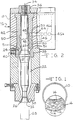
- FIG. 1 An end view of a plastic container 10 made from the die head of the present invention is shown in Figure 1.
- the plastic article 10 is blow molded from a plastic parison containing a matrix resin 12 such as high density polyethylene and a barrier resin such as SELAR RB which forms a plurality of discontinuous, thin layer barrier walls 14 in the matrix 12.
- the barrier walls 14 overlap one another in the wall of article 10 to provide a permeability barrier.
- the die head of the present invention is shown in cross-section in Figure 2 and designated generally at 16.
- the die head 16 is useful for the production of multiple parisons, in this case three parisons, of a matrix resin having a barrier resin forming barrier walls therein.
- the die head 16 is constructed of a die body 18 surrounding a generally cylindrically shaped mandrel 20 in a spaced relation thereto to form a tubular chamber 22.
- the chamber 22 includes an open upper end 24 and an annular outlet orifice 26 at its lower end.
- a tubular resin body is formed in the chamber 22 and extruded through the annular outlet orifice 26 to form a tubular parison, such as parison 28 shown below the outlet 26.
- the mandrel and the die body adjacent their lower ends, have radially inclined surfaces 30 and 32 respectively which are generally parallel to each other. Axial movement of the mandrel 20 in a direction parallel to the upright mandrel axis 34 will vary the spacing between the inclined surfaces 30 and 32 so as to regulate the resin flow rate through the outlet orifice 26 forming the parison 28.
- the mandrel is supported in the die body by a threaded collar 36 at the upper end of the die body which can be rotated to provide axial movement of the mandrel to adjust the resin flow rate.
- a flow adjusting ring 38 is included in the die body which is adjustable by a plurality of radial screws 40 to adjust the resin flow in the tubular chamber in order to balance the resin circumferentially in the annular chamber.
- a diverter sleeve 42 surrounds the mandrel and is positioned immediately above the chamber upper end 24.
- Sleeve 42 is used to form barrier walls from the barrier resin in the matrix resin.
- Sleeve 42 is in communication with an inlet passage 44 in the die body which is in turn in communication with an extrusion screw to receive molten resin from conduit 46.
- Conduits 46a and 46b feed resin to two other tubular chambers in the die head for producing multiple parisons.
- the inner surface 54 of the sleeve 42 is adjacent the mandrel with a portion of the sleeve inner surface 54 engaging the mandrel and a portion of the sleeve spaced from the mandrel as will be described below.
- the outer surface 58 of the sleeve is adjacent the die body with a portion of the sleeve outer surface 58 engaging the die body and a portion of the sleeve spaced from the die body.
- the sleeve 42 in cooperation with the mandrel and die body, forms two separated, counter-rotating spiral flow channels 48 and 50.
- the radially inner spiral flow channel 48 is formed by a spiral groove 52 machined in the inner surface 54 of the sleeve 42.
- Channel 48 directs the resin in a circumferential direction counterclockwise when viewed axially from the top of the die head 16.
- Outer channel 50 is formed by a spiral groove 56 machined into the outer surface 58 of the sleeve 42.
- the flow channel 50 directs the resin in a circumferentially clockwise direction when viewed axially from above the die head 16.
- the upper end of the two resin flow channels are in communication with one another through a connecting port 60 in the diverter sleeve 42.
- the connecting port 60 is disposed in alignment with the inlet passage 44 such that resin flow from the extrusion screw is divided in two, with a portion of the resin flowing through the inner spiral flow channel 48 and the remainder flowing through the outer spiral flow channel 50.
- the inner surface 54 of the diverter sleeve engages the mandrel during approximately one revolution of the spiral flow channel 48.
- the flow of resin is restricted to a circumferentially spiral flow intended to duplicate the circumferential resin flow in the extrusion screw.
- the sleeve inner wall 54 is spaced from the mandrel as shown at 62. This clearance between the mandrel and the sleeve allows a portion of the resin to flow vertically downward between the sleeve and the mandrel while the remaining portion of the resin in the inner flow channel continues to flow circumferentially.
- the clearance enables a gradual runoff of the resin from the sprial flow to a vertical flow to form the tubular parison. It is necessary to provide for a gradual runoff of the resin rather than releasing the resin from the spiral channel at a single point.
- the gradual runoff prevents an uncontrolled spread of the resin around the mandrel in a manner which could destroy the platelet structure and also prevents the formation of a localized thickening of the parison wall.
- the clearance between the mandrel and the sleeve provides a gradual runoff of resin as it continues to flow circumferentially, thus controlling the resin flow and providing a uniform wall thickness in the tubular parison.
- the outer surface 58 of the diverter sleeve engages the die body so that the resin flow in the outer spiral channel 50 is in a circumferential spiral direction. Again, after approximately one revolution, the outer surface of the sleeve is spaced from the die body as shown by the clearance 64 so that a portion of the resin will flow vertically downward between the sleeve and the die body while the remaining resin continues to flow circumferentially.
- the two resin streams merge together and flow through the open upper end 24 of the tubular chamber 22.
- the resin forms a tubular body which is extruded through the annular outlet 26 to form the tubular parison 28.
- the resin from the outer channel flows radially around the resin from the inner channel as the resin flows into the tubular chamber 22.
- the tubular resin body in chamber 22 is formed of two concentric layers.
- both the inner and outer layers have approximately equal amounts of resin.
- the developed length of each spiral channel is the same so that the resistance to flow through the channels will be substantially the same to produce equal resin flow rates through the two channels.
- the inner spiral flow channel is wrapped around a smaller diameter, it will have a greater number of revolutions around mandrel.
- the outer channel completes one revolution in the spiral channel before the clearance allows downward resin flow.
- the inner channel must complete more than one revolution.
- any gaps or windows in the overlapping barrier walls within one layer will likely be covered by barrier walls in the other layer.
- the two layers in the parison also prevent the formation of a weld line in the tubular parison that extends radially completely through the container wall. Each layer will have a weld line that extends radially through only that layer.
- the die head of the present invention provides a controlled structure of a barrier resin within a matrix resin, such as high density polyethylene, to form a tubular parison that includes a plurality of relatively thin, substantially two dimensional overlapping barrier walls in the matrix resin even though the structure of the barrier walls was destroyed by splitting the melt flow from one transfer tube into three conduits.
- a matrix resin such as high density polyethylene
- the diverter sleeve 42 while shown in a triple parison die head, can be used in die heads for producing other numbers of parisons.
- the diverter sleeve can also be used to form a parison of a single resin where the advantages previously discussed are desired such as faster color changes and the prevention of a single weld line through the parison.
- the die head of this invention achieves the objective of producing containers having a barrier performance equal to or greater than the barrier of containers produced with a single parison die head. This is accomplished by forming the barrier platelets in the die head immediately prior to the resin being extruded from the die head. By forming the platelet in the die head, there are no disruptions in the resin flow path which destroy the barrier structure after formation.
Landscapes
- Engineering & Computer Science (AREA)
- Mechanical Engineering (AREA)
- Manufacturing & Machinery (AREA)
- Blow-Moulding Or Thermoforming Of Plastics Or The Like (AREA)
- Extrusion Moulding Of Plastics Or The Like (AREA)
Priority Applications (2)
| Application Number | Priority Date | Filing Date | Title |
|---|---|---|---|
| EP90312645A EP0486735A1 (de) | 1990-11-20 | 1990-11-20 | Düsenkopf für Kunststoff mit sperrschichtbildendem Material |
| JP2318155A JPH04191028A (ja) | 1990-11-20 | 1990-11-26 | バリア形成材料を用いたプラスチック容器製造用ダイヘッド |
Applications Claiming Priority (1)
| Application Number | Priority Date | Filing Date | Title |
|---|---|---|---|
| EP90312645A EP0486735A1 (de) | 1990-11-20 | 1990-11-20 | Düsenkopf für Kunststoff mit sperrschichtbildendem Material |
Publications (1)
| Publication Number | Publication Date |
|---|---|
| EP0486735A1 true EP0486735A1 (de) | 1992-05-27 |
Family
ID=8205616
Family Applications (1)
| Application Number | Title | Priority Date | Filing Date |
|---|---|---|---|
| EP90312645A Ceased EP0486735A1 (de) | 1990-11-20 | 1990-11-20 | Düsenkopf für Kunststoff mit sperrschichtbildendem Material |
Country Status (2)
| Country | Link |
|---|---|
| EP (1) | EP0486735A1 (de) |
| JP (1) | JPH04191028A (de) |
Cited By (6)
| Publication number | Priority date | Publication date | Assignee | Title |
|---|---|---|---|---|
| CN102168774A (zh) * | 2011-04-21 | 2011-08-31 | 北京化工大学 | 一种交错熔接自增强管材及其成型方法 |
| WO2014149236A1 (en) * | 2013-03-15 | 2014-09-25 | Graham Packaging Company L.P. | Triple parison coextrusion multi-layer flowhead apparatus |
| CN109177110A (zh) * | 2018-09-21 | 2019-01-11 | 广州晶品智能压塑科技股份有限公司 | 用于制作瓶盖的均匀混料装置 |
| CN110171119A (zh) * | 2019-05-30 | 2019-08-27 | 王小兵 | 一种螺旋波纹管连续成型工艺 |
| CN110625569A (zh) * | 2019-09-26 | 2019-12-31 | 苏州船用动力系统股份有限公司 | 一种船舶推进轴系的轴套去除方法 |
| CN114829105A (zh) * | 2019-10-15 | 2022-07-29 | 考特斯机械制造有限公司 | 用于成型塑料型坯的挤出技术和软管形成技术 |
Families Citing this family (2)
| Publication number | Priority date | Publication date | Assignee | Title |
|---|---|---|---|---|
| US6652699B1 (en) * | 2000-02-17 | 2003-11-25 | Salflex Polymers Ltd. | Flanged member with barrier layer |
| US6368000B1 (en) * | 2000-05-23 | 2002-04-09 | Berol Corporation | Writing instrument and method of making same |
Citations (11)
| Publication number | Priority date | Publication date | Assignee | Title |
|---|---|---|---|---|
| US3026565A (en) * | 1961-01-04 | 1962-03-27 | Franklin Res And Dev Corp | Extruder head for hollow products |
| US3267194A (en) * | 1964-01-16 | 1966-08-16 | Owens Illinois Inc | Method and apparatus for feeding plastic material |
| DE1479328A1 (de) * | 1962-10-18 | 1969-04-17 | Ici Ltd | Blasverfahren und Vorrichtung zur Ausfuehrung des Verfahrens |
| FR2121565A1 (de) * | 1971-01-04 | 1972-08-25 | Kautex Werke Gmbh | |
| DE2440560A1 (de) * | 1973-09-11 | 1975-03-27 | Creusot Loire | Spritzkopf fuer kunststoff-schneckenspritzmaschinen |
| FR2265520A1 (en) * | 1974-03-30 | 1975-10-24 | Demag Ag | Screw extruder - for tubular products, using a tubular extruder |
| FR2369070A1 (fr) * | 1976-10-29 | 1978-05-26 | Ato Chimie | Procede de f |
| US4218416A (en) * | 1978-11-13 | 1980-08-19 | Baxter Travenol Laboratories, Inc. | Method for extruding a parison |
| EP0189270A2 (de) * | 1985-01-24 | 1986-07-30 | Mobil Oil Corporation | Verfahren zum Herstellen von Gegenständen aus Polymermischungen |
| EP0210725A1 (de) * | 1985-05-29 | 1987-02-04 | E.I. Du Pont De Nemours And Company | Nahtloser laminarer Gegenstand |
| EP0213789A2 (de) * | 1985-08-23 | 1987-03-11 | Hoover Universal, Inc. | Ringkolbenspeicherkopf mit Verteilerhülse |
-
1990
- 1990-11-20 EP EP90312645A patent/EP0486735A1/de not_active Ceased
- 1990-11-26 JP JP2318155A patent/JPH04191028A/ja active Pending
Patent Citations (11)
| Publication number | Priority date | Publication date | Assignee | Title |
|---|---|---|---|---|
| US3026565A (en) * | 1961-01-04 | 1962-03-27 | Franklin Res And Dev Corp | Extruder head for hollow products |
| DE1479328A1 (de) * | 1962-10-18 | 1969-04-17 | Ici Ltd | Blasverfahren und Vorrichtung zur Ausfuehrung des Verfahrens |
| US3267194A (en) * | 1964-01-16 | 1966-08-16 | Owens Illinois Inc | Method and apparatus for feeding plastic material |
| FR2121565A1 (de) * | 1971-01-04 | 1972-08-25 | Kautex Werke Gmbh | |
| DE2440560A1 (de) * | 1973-09-11 | 1975-03-27 | Creusot Loire | Spritzkopf fuer kunststoff-schneckenspritzmaschinen |
| FR2265520A1 (en) * | 1974-03-30 | 1975-10-24 | Demag Ag | Screw extruder - for tubular products, using a tubular extruder |
| FR2369070A1 (fr) * | 1976-10-29 | 1978-05-26 | Ato Chimie | Procede de f |
| US4218416A (en) * | 1978-11-13 | 1980-08-19 | Baxter Travenol Laboratories, Inc. | Method for extruding a parison |
| EP0189270A2 (de) * | 1985-01-24 | 1986-07-30 | Mobil Oil Corporation | Verfahren zum Herstellen von Gegenständen aus Polymermischungen |
| EP0210725A1 (de) * | 1985-05-29 | 1987-02-04 | E.I. Du Pont De Nemours And Company | Nahtloser laminarer Gegenstand |
| EP0213789A2 (de) * | 1985-08-23 | 1987-03-11 | Hoover Universal, Inc. | Ringkolbenspeicherkopf mit Verteilerhülse |
Cited By (8)
| Publication number | Priority date | Publication date | Assignee | Title |
|---|---|---|---|---|
| CN102168774A (zh) * | 2011-04-21 | 2011-08-31 | 北京化工大学 | 一种交错熔接自增强管材及其成型方法 |
| CN102168774B (zh) * | 2011-04-21 | 2013-04-10 | 北京化工大学 | 一种交错熔接自增强管材及其成型方法 |
| WO2014149236A1 (en) * | 2013-03-15 | 2014-09-25 | Graham Packaging Company L.P. | Triple parison coextrusion multi-layer flowhead apparatus |
| CN109177110A (zh) * | 2018-09-21 | 2019-01-11 | 广州晶品智能压塑科技股份有限公司 | 用于制作瓶盖的均匀混料装置 |
| CN109177110B (zh) * | 2018-09-21 | 2020-12-22 | 广州晶品智能压塑科技股份有限公司 | 用于制作瓶盖的均匀混料装置 |
| CN110171119A (zh) * | 2019-05-30 | 2019-08-27 | 王小兵 | 一种螺旋波纹管连续成型工艺 |
| CN110625569A (zh) * | 2019-09-26 | 2019-12-31 | 苏州船用动力系统股份有限公司 | 一种船舶推进轴系的轴套去除方法 |
| CN114829105A (zh) * | 2019-10-15 | 2022-07-29 | 考特斯机械制造有限公司 | 用于成型塑料型坯的挤出技术和软管形成技术 |
Also Published As
| Publication number | Publication date |
|---|---|
| JPH04191028A (ja) | 1992-07-09 |
Similar Documents
| Publication | Publication Date | Title |
|---|---|---|
| EP0280066B1 (de) | Vorrichtung und Verfahren zur Herstellung eines mehrschichtigen Gegenstandes, wie z.B. eines Vorformlings, beispielsweise zur Herstellung eines blasgeformten Behälters | |
| US5256051A (en) | Storage head for a blow molding machine | |
| AU599048B2 (en) | Extrusion head for extrusion molding | |
| US5069612A (en) | Modular tubular extrusion head | |
| US3354506A (en) | Apparatus for melt extrusion of multi-wall plastic tubing | |
| US5538411A (en) | Spiral fed multi-layer tubular die | |
| US5046938A (en) | Improved multiple layer die head with adjustable gaps | |
| ZA200300294B (en) | Tubular multilayer films, method and apparatus for preparing the same. | |
| AU635470B2 (en) | Die head for plastic with barrier forming material | |
| EP0486735A1 (de) | Düsenkopf für Kunststoff mit sperrschichtbildendem Material | |
| EP0213789B1 (de) | Ringkolbenspeicherkopf mit Verteilerhülse | |
| US5055022A (en) | Multiple parison extrusion device for producing laminar articles | |
| JP2824665B2 (ja) | 熱可塑性合成樹脂中空体の製造方法及び装置 | |
| US20030077347A1 (en) | Head for coextruding a thermoplastic parison | |
| US6551089B1 (en) | Extrusion head with spiral-channel distributor element | |
| US5114333A (en) | Die head for plastic with barrier forming material | |
| JPH02200404A (ja) | 押出ダイとこれを使って成形する押出体及びその成形方法 | |
| AU618922B2 (en) | Dual parison extrusion head for multi-layer blow molding | |
| US3545043A (en) | Apparatus for plastic film production | |
| CN115008719B (zh) | 一种拼接共挤机头及具有该机头的挤出设备 | |
| JPH07171879A (ja) | 多層ブロー成形用ダイス | |
| DE69402245T2 (de) | Extrusionskopf für Mehrschichtvorformlinge aus instabilen Materialkombinationen | |
| JP3869864B6 (ja) | 多層の管状の品物を押出し成形するための押出しヘッド | |
| SU1125133A1 (ru) | Экструзионна головка дл переработки пластмасс | |
| JPH05200838A (ja) | 熱可塑性樹脂成型装置 |
Legal Events
| Date | Code | Title | Description |
|---|---|---|---|
| PUAI | Public reference made under article 153(3) epc to a published international application that has entered the european phase |
Free format text: ORIGINAL CODE: 0009012 |
|
| 17P | Request for examination filed |
Effective date: 19911231 |
|
| AK | Designated contracting states |
Kind code of ref document: A1 Designated state(s): AT BE CH DE DK ES FR GB GR IT LI LU NL SE |
|
| 17Q | First examination report despatched |
Effective date: 19930819 |
|
| STAA | Information on the status of an ep patent application or granted ep patent |
Free format text: STATUS: THE APPLICATION HAS BEEN REFUSED |
|
| 18R | Application refused |
Effective date: 19940205 |