EP0486834B1 - Méthode d'accès multiple et système de radiocommunication mobile pour la mise en oeuvre de ladite méthode d'accès multiple - Google Patents
Méthode d'accès multiple et système de radiocommunication mobile pour la mise en oeuvre de ladite méthode d'accès multiple Download PDFInfo
- Publication number
- EP0486834B1 EP0486834B1 EP91118102A EP91118102A EP0486834B1 EP 0486834 B1 EP0486834 B1 EP 0486834B1 EP 91118102 A EP91118102 A EP 91118102A EP 91118102 A EP91118102 A EP 91118102A EP 0486834 B1 EP0486834 B1 EP 0486834B1
- Authority
- EP
- European Patent Office
- Prior art keywords
- sequence
- data streams
- spread
- delta
- filter
- Prior art date
- Legal status (The legal status is an assumption and is not a legal conclusion. Google has not performed a legal analysis and makes no representation as to the accuracy of the status listed.)
- Expired - Lifetime
Links
- 238000000034 method Methods 0.000 title claims abstract description 31
- 230000005540 biological transmission Effects 0.000 claims abstract description 25
- 230000008569 process Effects 0.000 claims description 13
- 230000004044 response Effects 0.000 claims description 13
- 230000010355 oscillation Effects 0.000 claims description 8
- 238000001914 filtration Methods 0.000 claims description 4
- 238000001208 nuclear magnetic resonance pulse sequence Methods 0.000 claims description 4
- 238000001228 spectrum Methods 0.000 claims description 4
- 230000008901 benefit Effects 0.000 abstract description 6
- 238000001514 detection method Methods 0.000 abstract description 2
- 238000000926 separation method Methods 0.000 abstract description 2
- 230000007480 spreading Effects 0.000 description 39
- 239000000284 extract Substances 0.000 description 4
- 238000004891 communication Methods 0.000 description 3
- 238000005516 engineering process Methods 0.000 description 3
- 230000035939 shock Effects 0.000 description 3
- 238000007476 Maximum Likelihood Methods 0.000 description 2
- 239000000654 additive Substances 0.000 description 2
- 230000000996 additive effect Effects 0.000 description 2
- 238000005314 correlation function Methods 0.000 description 2
- 230000003111 delayed effect Effects 0.000 description 2
- 238000010586 diagram Methods 0.000 description 2
- 230000000694 effects Effects 0.000 description 2
- 238000005457 optimization Methods 0.000 description 2
- 230000001419 dependent effect Effects 0.000 description 1
- 238000013461 design Methods 0.000 description 1
- 238000011161 development Methods 0.000 description 1
- 238000006073 displacement reaction Methods 0.000 description 1
- 238000011156 evaluation Methods 0.000 description 1
- 230000001771 impaired effect Effects 0.000 description 1
- 238000012545 processing Methods 0.000 description 1
- 230000001105 regulatory effect Effects 0.000 description 1
- 238000010845 search algorithm Methods 0.000 description 1
- 230000008054 signal transmission Effects 0.000 description 1
- 230000009897 systematic effect Effects 0.000 description 1
- 230000007704 transition Effects 0.000 description 1
Images

Classifications
-
- H—ELECTRICITY
- H04—ELECTRIC COMMUNICATION TECHNIQUE
- H04J—MULTIPLEX COMMUNICATION
- H04J13/00—Code division multiplex systems
- H04J13/0074—Code shifting or hopping
-
- H—ELECTRICITY
- H04—ELECTRIC COMMUNICATION TECHNIQUE
- H04B—TRANSMISSION
- H04B1/00—Details of transmission systems, not covered by a single one of groups H04B3/00 - H04B13/00; Details of transmission systems not characterised by the medium used for transmission
- H04B1/69—Spread spectrum techniques
- H04B1/707—Spread spectrum techniques using direct sequence modulation
- H04B1/7097—Interference-related aspects
- H04B1/7103—Interference-related aspects the interference being multiple access interference
-
- H—ELECTRICITY
- H04—ELECTRIC COMMUNICATION TECHNIQUE
- H04B—TRANSMISSION
- H04B2201/00—Indexing scheme relating to details of transmission systems not covered by a single group of H04B3/00 - H04B13/00
- H04B2201/69—Orthogonal indexing scheme relating to spread spectrum techniques in general
- H04B2201/707—Orthogonal indexing scheme relating to spread spectrum techniques in general relating to direct sequence modulation
- H04B2201/7097—Direct sequence modulation interference
- H04B2201/709709—Methods of preventing interference
-
- H—ELECTRICITY
- H04—ELECTRIC COMMUNICATION TECHNIQUE
- H04J—MULTIPLEX COMMUNICATION
- H04J13/00—Code division multiplex systems
- H04J13/0007—Code type
- H04J13/0022—PN, e.g. Kronecker
Definitions
- the invention relates to a multiple access method for the simultaneous exchange of several data streams between several participants in a transmission system, wherein different data streams with the same spreading sequence are spread to form a corresponding DSSS signal and the different DSSS signals are superimposed on the transmission to form a single received signal.
- the signals from different participants should ideally be orthogonal. Ie that the receiver of the mobile station resp. the base station that the base station resp. the mobile station can filter out the signal intended for it in such a way that no signal components from other users are available.
- DSSS-CDMA Direct Sequence Spread Spectrum
- CDMA Code Division Multiple Access
- TDMA Time Division Multiple Access
- TDMA time division multiple access
- each symbol of the data stream is multiplied and transmitted by a predetermined spreading sequence.
- each data bit determines the polarity of an entire pulse sequence made up of L "chips".
- a chip can have the value +1 or -1. So that the individual users can be separated, each is assigned its own spreading sequence.
- the transmitted signal is processed by a filter bank with K matched filters.
- Each of the K filters is adapted to the spreading sequence of one of the users.
- the sequences have to be defined in such a way that the cross-correlation between different spreading sequences and thus also the interference between the different data streams is as small as possible.
- CDMA systems are no longer necessary to maintain precise synchronization between the participants. In fact, such systems are usually operated completely asynchronously.
- Another advantage is that the transmitters transmit continuously. I.e. the peak power essentially coincides with the average power.
- the main disadvantage is that the interference from other users cannot be neglected. This interference is particularly pronounced when users are received with very different field strengths ("near-far effect"). For this reason, the transmission line of the users is often regulated.
- the ratio of peak power to average power can be kept low, as in CDMA, but the good properties of the Aloha principle with regard to preventing packet collisions in the time domain (so-called "collision resolution") are not greatly deteriorated.
- a disadvantage of the method is that the spread cannot be completely reversed by matched filtering.
- the object of the invention is to provide a multiple access method of the type mentioned at the outset which avoids the problems existing in the prior art.
- the aim of the invention is to propose a system which enables a large number of subscribers to share the same frequency spectrum in a manner which is advantageous compared to both TDMA and DSSS-CDMA.
- the solution consists in filtering the received signal in a filter that is inverse with respect to the common spreading sequence in order to detect the different data streams in a receiver, and in that the superimposition is carried out in such a way that the spreading sequence intervals belonging to different data streams are shifted in time from one another by a predetermined minimum value .
- the essence of the method according to the invention is the use of an inverse filter instead of a matched filter. This enables the implementation of a multiple access system, that avoids the so-called inter-user interference without requiring precise synchronization.
- the time shift of the spreading sequence intervals belonging to different data streams is greater than the duration of a chip plus the duration of the burst response of a channel used for the transmission of the corresponding DSSS signal. This allows the individual users to be clearly separated from one another. It is also possible to estimate the channel impulse response for each transmission channel in the detector.
- the protocol becomes particularly simple if the time shift compared to neighboring spreading sequence intervals is approximately the same for all spreading sequence intervals belonging to different data streams.
- the inverse filter is a discrete-time filter that responds to the specified spreading sequence as such with a Kronecker delta sequence.
- An optimal or at least relatively optimal spreading sequence s [.] Is determined such that the process gain G, defined by the inverse of the energy of the associated inverse filter: with respect to all or as many spreading sequences of given length L as possible.
- One way to ensure that the minimum time intervals are observed is to transmit synchronization signals to the participants in the transmission system via a separate channel.
- the method according to the invention is well suited for mobile radio systems.
- One example is microcellular mobile radio, where the mobile subscriber stations move within a radius of typically several meters to a maximum of about 100 meters of a base station.
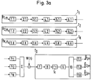
- Fig. 1 illustrates the principle of the invention.
- the transmission should take place in the same HF range.
- several transmitters will modulate their data streams onto a carrier oscillation, the frequency of which is the same for all.
- the data streams ⁇ B 1, m ⁇ , ⁇ B 2, m ⁇ , ⁇ B 3, m ⁇ contain digital (eg binary) data in the form of symbols B 1, m , B 2, m , B 3, m , which in the each data stream occur with a predetermined symbol duration T.
- the result of this transition from T to T / L is a DSSS signal ⁇ B 1, m s [.] ⁇ .
- Each data stream ⁇ B 1, m ⁇ , ⁇ B 2, m ⁇ , ⁇ B 3, m ⁇ becomes a corresponding DSSS signal (B 1, m s [.] ⁇ , ⁇ B 2, m s [.] ⁇ , ⁇ B 3, m s [.] ⁇
- the third te DSSS signal ⁇ B 3, m s [.] ⁇ is delayed by Delta_T compared to the second ⁇ B 2, m s [.] ⁇ and by 2 Delta_T compared to the first ⁇ B 1, m s [.] ⁇ .
- a receiver who is interested in a specific one of the data streams must therefore first filter this out of the received signal. According to the invention, this is done with an approximate inverse filter.
- the ideal inverse filter sought is an inverse filter with regard to the spreading sequence. This has the property that it responds to the specified spreading sequence as such with a pure Kronecker delta sequence ⁇ [k]. This will be explained in more detail below.
- the receiver differs from a known DSSS receiver by the use of an approximate inverse filter instead of a matched filter.
- the inverse filter has a completely different effect. His response to the spreading sequence as such produces a Kronecker delta sequence. As is known, such a sequence is distinguished by the fact that it has only one sample value that is different from zero.
- the impulse response of the filter is limited to a length -M1 ⁇ k ⁇ L + M2. Outside this window, the filter coefficients v [k] are identical to zero.
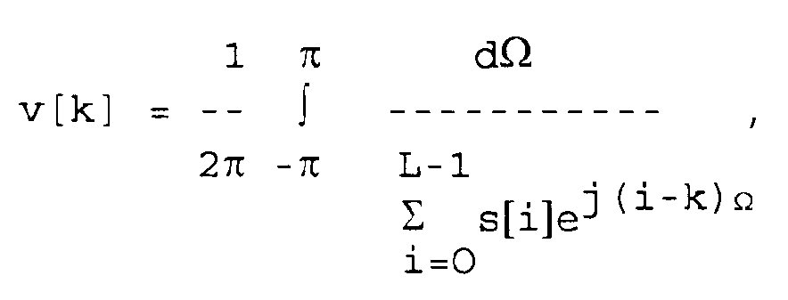
- the filter coefficients v [k] other than zero are selected according to the invention such that when the filter is excited by the spreading sequence, the resulting output signal approximates the Kronecker delta sequence as closely as possible.
- the coefficients v [k] of the ideal inverse filter decay exponentially in the case of a suitably selected spreading sequence for large k, reasonably good results can also be achieved with filters of reasonable length.
- the filter coefficients correspond to the ideal case, outside the specified range they are simply set to zero.
- the approximate inverse filter thus corresponds to the cut off ideal inverse filter (M 1 and M 2 are predeterminable numbers, ie so-called design parameters).
- the approximated inverse filter responds when excited by the specified spreading sequence s [.] As such with an output sequence which approximates the Kronecker delta sequence in the sense of the smallest error squares.
- the output sequence has a maximum peak / off peak ratio in the case mentioned. I.e. the largest secondary peak is made as small as possible in relation to the main peak. This is an approximate realization of the infinitely large peak / off peak ratio of a Kronecker delta sequence.
- the received signal is filtered with an inverse filter, this has the consequence that a signal is produced which can be divided into periodically recurring time slots, each time slot containing information about a symbol.
- the length of a time slot corresponds to the time shift of the various corresponding DSSS signals ⁇ B 1, ms [.] ⁇ , ⁇ B 2, ms [.] ⁇ , ⁇ B 3, ms [.] ⁇ In the transmitters.
- the different data streams come from different subscribers.
- An undeformed DSSS signal produces a sequence of pulses at the filter output mentioned.
- the pulses have a time interval T (symbol duration) and are weighted in accordance with the respective symbol value of the data stream.
- the output signal Y [k] shown in FIG. 2 is therefore composed in principle of weighted channel impulse responses.
- Y [k] has essentially (ie apart from noise components) the course B 1, m h 1, B 1, m denoting the symbol value and h 1 the channel shock response of the channel between the first user and the receiver.
- the output signal corresponds analogously to that with the next one Symbol value of the data stream multiplied channel impulse response: B 1, m + 1 h 1 .
- the receiver extracts all the associated time slots (ie for the kth data stream, the kth time slots of a frame from K time slots), filters this extracted signal with a channel-matched matched filter (whose shock response is known to be h * [-. ] is), extracts the real part of the resulting signal and performs a threshold detection.
- ML maximum likelihood
- the time shift Delta_T of the spreading sequence intervals belonging to different data streams is greater than the duration of the burst response of a channel used for the transmission of the corresponding DSSS signal.
- the individual users can be clearly separated from one another because the signal components belonging to different data streams in the received signal do not overlap in any way. It is also possible, according to an advantageous embodiment estimate the channel shock response for each transmission channel with the detector.
- the time shift should not fall below a predetermined minimum value, otherwise the received signal can no longer be demultiplexed.
- This lower limit preferably corresponds to the longest occurring channel impulse response plus a chip duration and is essentially the same for all DSSS signals.
- time shift Delta_T is set once and for all (e.g. when implementing the system). However, there is also the possibility of adapting them to the specific circumstances of the transmission channels.
- a preferred alternative is to provide a separate synchronization channel in addition to the common data channel during the implementation.
- this synchronization channel e.g. by the base station
- synchronization signals for compliance with the minimum time intervals are sent to the participants in the transmission system.
- additional channels are e.g. also used in TDMA systems.
- the spreading sequence s [.] Is defined such that the process gain G, defined by the inverse of the energy of the associated inverse filter: with respect to as many, in particular all, spreading sequences of the same length is maximal.
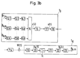
- 3a, b shows a block diagram of a mobile radio system according to the invention. It includes a base station T0 and K mobile subscriber stations T1, ..., T K. All stations are equipped with both a transmitter and a receiver circuit to enable two-way communication.
- Fig. 3a the transmitters of the subscriber stations T1, ..., T K and the receiver of the base station T0 and in Fig. 3b the receivers of the subscriber stations T1, ..., T K and the transmitter of the base station T0 are shown.
- a delay element 2.K brings the required time shift (K-1) T C towards the other participants in the data stream.
- the spreading sequence generator 3.K the predetermined common spreading sequence s [.] Is multiplied by the symbol value present in each case.
- the digital DSSS signal is generated in this way. With a pulse modulator 4.K and a low-pass filter 5.K, a continuous-time DSSS signal is generated, which is then modulated onto a carrier oscillation in a conventional modulator 6.K.
- the individual subscriber stations T1, ..., T K are in principle all the same. In operation, they differ only in the delay with which they provide their data stream.
- the signals are deformed and noisy through the respective channels h 1, h 2, ..., h K (additive white Gaussian noise W (t)).
- the signals from the various subscriber stations ( ⁇ ) overlap in the receiver.
- the receiver of the base station T0 demodulates the carrier oscillation (demodulator 7), filters out the relevant frequency range (filter 8) and samples the filtered signal at the chip rate 1 / T C.
- the received signal X [i] is filtered with an inverse filter 9. This gives an output signal Y [k] with the properties explained with reference to FIG. 2.
- a selection circuit 10 extracts the time slots belonging to the same data stream.
- An ML detector 11.1, ..., 11.K then follows for each data stream.
- the delayed signals are processed in spreading sequence generators 14.1 ... 14.K into DSSS signals.
- a summing circuit 15 superimposes the K DSSS signals into a digital transmission signal U (i). This is processed in a manner known per se using a pulse modulator 16 and a low-pass filter 17 to form a continuous-time signal U (t).
- a modulator 18 modulates a predetermined carrier oscillation in accordance with the continuous-time signal U (t).
- the modulated carrier oscillation When transmitted to the k-th subscriber station T k , the modulated carrier oscillation undergoes deformation in the channel h k and is impaired by an additive white Gaussian noise W (t).
- the subscriber station T k demodulates the carrier oscillation and filters out the desired frequency range (demodulator 19, filter 20).
- the resulting received signal X k (t) is sampled with an integer multiple of the chip rate 1 / T C and then filtered with the inverse filter 21.
- the sampled received signal is thereby despread.
- a selection circuit 22 extracts the time slots assigned to the subscriber station T k (for example always the kth from a frame of K time slots) in accordance with the method according to the invention. In this way, a signal Y k is obtained, from which the data stream (B k, m marked with a roof) can be estimated with an ML detector 23.
- the invention creates a multiple access method which combines the advantages of TDMA and CDMA.
- a practically total separation of users is possible without the need for the precision of synchronization that is customary with TDMA.
Landscapes
- Engineering & Computer Science (AREA)
- Computer Networks & Wireless Communication (AREA)
- Signal Processing (AREA)
- Mobile Radio Communication Systems (AREA)
- Synchronisation In Digital Transmission Systems (AREA)
- Time-Division Multiplex Systems (AREA)
Claims (9)
- Méthode d'accès multiple pour l'échange simultané de plusieurs flux de données ({B1,m}, {B2,m}, {B3,m}) entre plusieurs abonnés (T₀, ..., TK) d'un système de transmission, chacun des flux de données ({B1,m}, {B2,m}, {B3,m}) étant écarté avec la même séquence d'écartement (s[.]) par rapport à un signal DSSS (DSSS = Direct Sequence Spread Spectrum) approprié et les divers signaux DSSS ({B1,ms[.]}, {B2,ms[.]}, {B3,ms[.]}) étant superposés lors de la transmission en un signal de transmission unique, caractérisée en ce que, pour détecter l'un des divers flux de données ({B1,m}, {B2,m}, {B3,m}) dans un récepteur, le signal de réception est filtré dans un filtre (9, 21) inverse par rapport à la séquence d'écartement (s[.]) commune et la superposition se fait de telle façon que les intervalles de séquence d'écartement (B1,mSi, B2,mSi,...) appartenant aux divers flux de données ({B1,m}, {B2,m}, {B3,m}) sont décalés dans le temps les uns par rapport aux autres d'une valeur (Delta_T) minimale prédéfinie.
- Méthode d'accès multiple selon la revendication 1, caractérisée en ce que le décalage dans le temps (Delta_T) des intervalles de séquence d'écartement (B1,mSi, B2,mSi, ...) appartenant à divers flux de données ({B1,m}, {B2,m}, {B3,m}) est supérieur à une durée de puce (T₀) plus la durée de la réponse impulsionnelle d'un canal (hk(t)) utilisé pour la transmission du signal DSSS correspondant.
- Méthode d'accès multiple selon la revendication 1 ou 2, caractérisée en ce que le décalage dans le temps (Delta_T) par rapport à des intervalles de séquence d'écartement (B1,mSi, B2,mSi, ...) voisins est sensiblement égal pour tous les intervalles de séquence d'écartement (B1,mSi, B2,mSi, ...) appartenant à divers flux de données ({B1,m}, {B2,m}, {B3,m}).
- Méthode d'accès multiple selon l'une quelconque des revendications 1 à 3, caractérisée en ce que le filtre inverse (9, 21) est choisi de telle façon que, en cas d'excitation par la séquence d'impulsion (s[.]) prédéfinie en tant que telle, il répond approximativement avec une séquence delta Kronecker (δ[k]) comme séquence initiale.
- Méthode d'accès multiple selon l'une quelconque des revendications 1 à 4, caractérisée en ce que les coefficients v[k] du filtre inverse (9, 21) faisant partie de la séquence d'écartement s[.] sont choisis dans le sens de l'une des trois approximations suivantes, à savoir soita) filtre inverse tronqué, selon la formule
v[k] = 0 , pour k < -M₁ et k > L+M₂ ;b) moindres carrés
les coefficients v[k], k = -M₁ . . . L+M₂, étant définis de telle façon que, en cas d'excitation par la séquence d'impulsion (s[.]) prédéfinie en tant que telle, le filtre inverse approché par approximation répond avec une séquence initiale qui approche la séquence Delta Kronecker (δ[k]) dans le sens des moindres carrés ; ouc) rapport POP maximum
le filtre inverse (9, 21) approché par approximation répondant avec un nombre prédéfini de coefficients v[k], k = -M₁ ...L+M₂, en cas d'excitation par la séquence d'impulsion (s[.]) prédéfinie en tant que telle avec une séquence initiale qui approche la séquence delta Kronecker (δ[k] dans le sens d'un rapport Peak/Off Peak maximum. - Méthode d'accès multiple selon l'une quelconque des revendications 1 à 5, caractérisée en ce que la séquence d'écartement s[.] est fixée de telle façon que le gain de processus G, défini par l'inverse de l'énergie du filtre inverse associé :

- Méthode d'accès multiple selon l'une quelconque des revendications 1 à 6, caractérisée en ce que, pour respecter les intervalles de temps minimum, des signaux de synchronisation sont transmis par un canal séparé aux abonnés (T₁, TK) du système de transmission.
- Système radiotéléphonique mobile pour l'application de la méthode d'accès multiple selon la revendication 1, comprenant au moins une station de base (T₀) et plusieurs stations d'abonné (T₁, ..., TK) avec dispositifs de couplage émetteur/récepteur comprenant chacun un circuit (3.1, ..., 3.K, 14.1, ..., 14.K), afin d'écarter chacun des divers flux de données ({B1,m}, {B2,m}, {B3,m}) avec la même séquence d'écartement (s[.]) par rapport à un signal DSSS correspondant et un circuit (15) dans la station de base (T₀), pour superposer les divers signaux DSSS ({B1,ms[.]}, {B2,ms[.]}, {B3,ms[.]}) pour la transmission à un seul signal de réception, le dispositif de couplage émetteur présentant un filtre inverse (9, 21) pour détecter l'un des divers flux de données ({B1,m}, {B2,m}, {B3,m}), afin de filtrer en sens inverse le signal de réception par rapport à la séquence d'écartement commune, et des éléments de retard (2.1, ..., 2K, 13.1, ..., 13K) étant prévus, qui décalent dans le temps les intervalles de séquences d'écartement (B1,mSi, B2,mSi,...) appartenant aux divers flux de données ({B1,m}, {B2,m}, {B3,m}) les uns par rapport aux autres d'une valeur (Delta_T) minimale prédéfinie.
- Système radiotéléphonique mobile selon la revendication 8, caractérisé en ce que les stations d'abonnés (T₁, ..., TK) et la station de base (T₀) présentent des moyens (18) pour moduler une oscillation porteuse selon un signal DSSS donné, l'oscillation porteuse étant la même pour toutes les stations d'abonné (T₁, ..., TK) et la station de base (T₀).
Applications Claiming Priority (2)
| Application Number | Priority Date | Filing Date | Title |
|---|---|---|---|
| CH3702/90 | 1990-11-22 | ||
| CH370290 | 1990-11-22 |
Publications (2)
| Publication Number | Publication Date |
|---|---|
| EP0486834A1 EP0486834A1 (fr) | 1992-05-27 |
| EP0486834B1 true EP0486834B1 (fr) | 1995-11-22 |
Family
ID=4261690
Family Applications (1)
| Application Number | Title | Priority Date | Filing Date |
|---|---|---|---|
| EP91118102A Expired - Lifetime EP0486834B1 (fr) | 1990-11-22 | 1991-10-24 | Méthode d'accès multiple et système de radiocommunication mobile pour la mise en oeuvre de ladite méthode d'accès multiple |
Country Status (5)
| Country | Link |
|---|---|
| US (1) | US5170412A (fr) |
| EP (1) | EP0486834B1 (fr) |
| JP (1) | JPH04351130A (fr) |
| AT (1) | ATE130712T1 (fr) |
| DE (1) | DE59106942D1 (fr) |
Families Citing this family (66)
| Publication number | Priority date | Publication date | Assignee | Title |
|---|---|---|---|---|
| US5285469A (en) * | 1991-06-03 | 1994-02-08 | Omnipoint Data Corporation | Spread spectrum wireless telephone system |
| DE69331375T2 (de) * | 1992-11-04 | 2002-08-14 | Ntt Mobile Communications Network Inc., Tokio/Tokyo | Mobiles kommunikationssystem mit kodemultiplexvielfachzugriff |
| US5341395A (en) * | 1992-11-24 | 1994-08-23 | At&T Bell Laboratories | Data recovery technique for asynchronous CDMA systems |
| FI925472L (fi) * | 1992-12-01 | 1994-06-02 | Nokia Mobile Phones Ltd | Tiedonsiirtomenetelmä sekä -järjestelmä |
| US5345468A (en) * | 1992-12-16 | 1994-09-06 | At&T Bell Laboratories | Despreading technique for CDMA systems |
| WO1994021056A1 (fr) * | 1993-03-05 | 1994-09-15 | Ntt Mobile Communications Network Inc. | Procede de communication a acces selectif par amdc, et systeme pour stations mobiles dans lequel ledit procede est utilise |
| FI933129A0 (fi) * | 1993-07-08 | 1993-07-08 | Nokia Mobile Phones Ltd | Dataoeverfoeringsfoerfarande foer ett digitalt cellulaert mobiltelefonsystem och ett digitalt cellulaert mobiltelefonsystem |
| US5537434A (en) * | 1993-10-25 | 1996-07-16 | Telefonaktiebolaget Lm Ericsson | Frequency hopping control channel in a radio communication system |
| US6088590A (en) * | 1993-11-01 | 2000-07-11 | Omnipoint Corporation | Method and system for mobile controlled handoff and link maintenance in spread spectrum communication |
| US6005856A (en) | 1993-11-01 | 1999-12-21 | Omnipoint Corporation | Communication protocol for spread spectrum wireless communication system |
| US5436941A (en) * | 1993-11-01 | 1995-07-25 | Omnipoint Corporation | Spread spectrum spectral density techniques |
| IL111469A0 (en) * | 1993-11-01 | 1994-12-29 | Omnipoint Corp | Despreading/demodulating direct sequence spread spectrum signals |
| US6094575A (en) * | 1993-11-01 | 2000-07-25 | Omnipoint Corporation | Communication system and method |
| JP3003839B2 (ja) * | 1993-11-08 | 2000-01-31 | エヌ・ティ・ティ移動通信網株式会社 | Cdma通信方法および装置 |
| FR2713418B1 (fr) * | 1993-11-30 | 1995-12-29 | Thomson Csf | Procédé de transmission par paquets et émetteur et récepteur mettant en Óoeuvre ce procédé. |
| JP2636712B2 (ja) * | 1993-12-08 | 1997-07-30 | 日本電気株式会社 | 移動通信装置 |
| JP2734952B2 (ja) * | 1993-12-16 | 1998-04-02 | 日本電気株式会社 | Cdma基地局受信装置 |
| JPH07245597A (ja) * | 1994-03-02 | 1995-09-19 | Pioneer Electron Corp | スペクトラム拡散通信方法及び送受信装置 |
| JP3302168B2 (ja) * | 1994-04-05 | 2002-07-15 | 株式会社東芝 | 移動無線通信システム |
| FR2721784B1 (fr) * | 1994-06-24 | 1996-07-19 | Thomson Csf | Procédé, émetteur et récepteur pour la transmission d'informations par paquets. |
| US5754585A (en) | 1994-09-09 | 1998-05-19 | Omnipoint Corporation | Method and apparatus for serial noncoherent correlation of a spread spectrum signal |
| US5610940A (en) | 1994-09-09 | 1997-03-11 | Omnipoint Corporation | Method and apparatus for noncoherent reception and correlation of a continous phase modulated signal |
| US5754584A (en) | 1994-09-09 | 1998-05-19 | Omnipoint Corporation | Non-coherent spread-spectrum continuous-phase modulation communication system |
| US5832028A (en) | 1994-09-09 | 1998-11-03 | Omnipoint Corporation | Method and apparatus for coherent serial correlation of a spread spectrum signal |
| US5881100A (en) | 1994-09-09 | 1999-03-09 | Omnipoint Corporation | Method and apparatus for coherent correlation of a spread spectrum signal |
| US5629956A (en) | 1994-09-09 | 1997-05-13 | Omnipoint Corporation | Method and apparatus for reception and noncoherent serial correlation of a continuous phase modulated signal |
| US5856998A (en) | 1994-09-09 | 1999-01-05 | Omnipoint Corporation | Method and apparatus for correlating a continuous phase modulated spread spectrum signal |
| US5659574A (en) | 1994-09-09 | 1997-08-19 | Omnipoint Corporation | Multi-bit correlation of continuous phase modulated signals |
| US5627856A (en) | 1994-09-09 | 1997-05-06 | Omnipoint Corporation | Method and apparatus for receiving and despreading a continuous phase-modulated spread spectrum signal using self-synchronizing correlators |
| US5648982A (en) | 1994-09-09 | 1997-07-15 | Omnipoint Corporation | Spread spectrum transmitter |
| US5757847A (en) | 1994-09-09 | 1998-05-26 | Omnipoint Corporation | Method and apparatus for decoding a phase encoded signal |
| US5963586A (en) | 1994-09-09 | 1999-10-05 | Omnipoint Corporation | Method and apparatus for parallel noncoherent correlation of a spread spectrum signal |
| US5953370A (en) | 1994-09-09 | 1999-09-14 | Omnipoint Corporation | Apparatus for receiving and correlating a spread spectrum signal |
| JP3215018B2 (ja) * | 1994-09-09 | 2001-10-02 | 三菱電機株式会社 | 移動通信システム |
| US5680414A (en) | 1994-09-09 | 1997-10-21 | Omnipoint Corporation | Synchronization apparatus and method for spread spectrum receiver |
| US5692007A (en) | 1994-09-09 | 1997-11-25 | Omnipoint Corporation | Method and apparatus for differential phase encoding and decoding in spread-spectrum communication systems with continuous-phase modulation |
| US5625642A (en) * | 1994-10-11 | 1997-04-29 | Lucent Technologies Inc. | Spread-response precoding system having signature sequences longer than the inter-symbol time interval |
| US5570351A (en) * | 1994-10-11 | 1996-10-29 | Lucent Technologies Inc. | Multi-user communication system employing spread signatures |
| US5742583A (en) * | 1994-11-03 | 1998-04-21 | Omnipoint Corporation | Antenna diversity techniques |
| FI97583C (fi) | 1995-02-02 | 1997-01-10 | Nokia Mobile Phones Ltd | Tiedonsiirtomenetelmä, lähetin ja vastaanotin |
| US5784403A (en) * | 1995-02-03 | 1998-07-21 | Omnipoint Corporation | Spread spectrum correlation using saw device |
| US5627855A (en) * | 1995-05-25 | 1997-05-06 | Golden Bridge Technology, Inc. | Programmable two-part matched filter for spread spectrum |
| US5959980A (en) * | 1995-06-05 | 1999-09-28 | Omnipoint Corporation | Timing adjustment control for efficient time division duplex communication |
| US5689502A (en) * | 1995-06-05 | 1997-11-18 | Omnipoint Corporation | Efficient frequency division duplex communication system with interleaved format and timing adjustment control |
| US5802046A (en) * | 1995-06-05 | 1998-09-01 | Omnipoint Corporation | Efficient time division duplex communication system with interleaved format and timing adjustment control |
| US5745484A (en) * | 1995-06-05 | 1998-04-28 | Omnipoint Corporation | Efficient communication system using time division multiplexing and timing adjustment control |
| US6041046A (en) * | 1995-07-14 | 2000-03-21 | Omnipoint Corporation | Cyclic time hopping in time division multiple access communication system |
| US5960028A (en) * | 1995-08-11 | 1999-09-28 | Sharp Kabushiki Kaisha | Spread spectrum communication system |
| US6108364A (en) * | 1995-08-31 | 2000-08-22 | Qualcomm Incorporated | Time division duplex repeater for use in a CDMA system |
| US5844894A (en) * | 1996-02-29 | 1998-12-01 | Ericsson Inc. | Time-reuse partitioning system and methods for cellular radio telephone systems |
| US5606548A (en) * | 1996-04-16 | 1997-02-25 | Nokia Mobile Phones Limited | Mobile terminal having improved digital control channel (DCCH) search procedure |
| JP2800891B2 (ja) * | 1996-12-17 | 1998-09-21 | 日本電気株式会社 | Cdma方式のマルチコード送信装置 |
| US6282228B1 (en) * | 1997-03-20 | 2001-08-28 | Xircom, Inc. | Spread spectrum codes for use in communication |
| US6151354A (en) * | 1997-12-19 | 2000-11-21 | Rockwell Science Center | Multi-mode, multi-band, multi-user radio system architecture |
| US6947469B2 (en) | 1999-05-07 | 2005-09-20 | Intel Corporation | Method and Apparatus for wireless spread spectrum communication with preamble processing period |
| US7031371B1 (en) | 2000-09-25 | 2006-04-18 | Lakkis Ismail A | CDMA/TDMA communication method and apparatus for wireless communication using cyclic spreading codes |
| US7403576B2 (en) | 2001-12-06 | 2008-07-22 | Pulse-Link, Inc. | Systems and methods for receiving data in a wireless communication network |
| US7317756B2 (en) | 2001-12-06 | 2008-01-08 | Pulse-Link, Inc. | Ultra-wideband communication apparatus and methods |
| US7483483B2 (en) | 2001-12-06 | 2009-01-27 | Pulse-Link, Inc. | Ultra-wideband communication apparatus and methods |
| US8045935B2 (en) | 2001-12-06 | 2011-10-25 | Pulse-Link, Inc. | High data rate transmitter and receiver |
| US7391815B2 (en) | 2001-12-06 | 2008-06-24 | Pulse-Link, Inc. | Systems and methods to recover bandwidth in a communication system |
| US7406647B2 (en) | 2001-12-06 | 2008-07-29 | Pulse-Link, Inc. | Systems and methods for forward error correction in a wireless communication network |
| US7450637B2 (en) | 2001-12-06 | 2008-11-11 | Pulse-Link, Inc. | Ultra-wideband communication apparatus and methods |
| WO2007008431A2 (fr) * | 2005-07-06 | 2007-01-18 | The Penn State Research Foundation | Capteur de detection et de localisation d'intrusion connecte en reseau a guide d'onde multibande |
| US10623468B1 (en) | 2014-05-30 | 2020-04-14 | Mbr Innovations Llc | Systems and methods for simultaneous electronic file exchange |
| US10957445B2 (en) | 2017-10-05 | 2021-03-23 | Hill-Rom Services, Inc. | Caregiver and staff information system |
-
1991
- 1991-10-24 DE DE59106942T patent/DE59106942D1/de not_active Expired - Fee Related
- 1991-10-24 EP EP91118102A patent/EP0486834B1/fr not_active Expired - Lifetime
- 1991-10-24 AT AT91118102T patent/ATE130712T1/de not_active IP Right Cessation
- 1991-11-15 JP JP3353521A patent/JPH04351130A/ja active Pending
- 1991-11-21 US US07/795,478 patent/US5170412A/en not_active Expired - Fee Related
Also Published As
| Publication number | Publication date |
|---|---|
| DE59106942D1 (de) | 1996-01-04 |
| JPH04351130A (ja) | 1992-12-04 |
| ATE130712T1 (de) | 1995-12-15 |
| US5170412A (en) | 1992-12-08 |
| EP0486834A1 (fr) | 1992-05-27 |
Similar Documents
| Publication | Publication Date | Title |
|---|---|---|
| EP0486834B1 (fr) | Méthode d'accès multiple et système de radiocommunication mobile pour la mise en oeuvre de ladite méthode d'accès multiple | |
| DE69815105T2 (de) | Mobilstationssynchronisation in einem spreizspektrumnachrichtenübertragunssystem | |
| DE69331375T2 (de) | Mobiles kommunikationssystem mit kodemultiplexvielfachzugriff | |
| DE69433336T2 (de) | Cdma kommunikationsverfahren mit selektivem zugriff und anordnung für mobile stationen in denen dieses verfahren angewandt wird | |
| DE60118715T2 (de) | Korrelationsfilter für den rückkanal in einem drahtlosen cdma system mit mehreren bit-raten | |
| DE60016664T2 (de) | Verfahren zur gemeinsamen Erfassung eines Satzes von CDMA-Codes | |
| EP0361299B1 (fr) | Système de transmission radio numérique pour réseau cellulaire utilisant la technique de l'étalement de spectre | |
| EP1006670B1 (fr) | Réseau sans fil | |
| DE3527329A1 (de) | Digitales funkuebertragungssystem mit variabler zeitschlitzdauer der zeitschlitze im zeitmultiplexrahmen | |
| DE3527331A1 (de) | Digitales funkuebertragungssystem | |
| DE20218534U1 (de) | Ein TDD-Knoten B, der während der Zellsuche primäre und sekundäre Synchronisationscodes verwendet | |
| EP0151280B1 (fr) | Procédé en multiplexage de temps pour un système cellulaire numérique | |
| DE19747367C2 (de) | Verfahren und Anordnung zur Übertragung von Daten über eine Funkschnittstelle in einem Funk-Kommunikationssystem | |
| EP1021003A2 (fr) | Réseau sans fil | |
| DE10038187B4 (de) | Verfahren zum Übertragen in nicht-orthogonalen physikalischen Kanälen im Kommunikationssystem | |
| DE60310067T2 (de) | Datenschätzung auf der Basis einer segmentweisen Kanalentzerrung | |
| EP0967742A2 (fr) | Réseau sans fil | |
| DE69828250T2 (de) | Digitale Direktsequenzspreizspektrumnachrichtenübertragung mit Störsignalgeneration | |
| DE69934883T2 (de) | Reduzierung der flussdichte in einem ocdma-satellitenkommunikationssystem | |
| DE69835816T2 (de) | Verfahren und Vorrichtung zum Empfang | |
| DE60038063T2 (de) | Verminderung der Rechenkomplexität in Joint-Detektion | |
| EP2689535B1 (fr) | Méthode er décodeur pour désétaler des signaux de données étalés par des séquences de walsh | |
| DE19625859C1 (de) | Verfahren und Signalauswerteeinrichtung zur Ermittlung des Störanteils im Signalgemisch des Empfangssignals einer CDMA-Empfangseinrichtung | |
| DE60023227T2 (de) | Drahtloses Kommunikationssystem | |
| DE69901276T2 (de) | Multirate, Multikode CDMA Übertragung für ein zellulares Mobilfunksystem |
Legal Events
| Date | Code | Title | Description |
|---|---|---|---|
| PUAI | Public reference made under article 153(3) epc to a published international application that has entered the european phase |
Free format text: ORIGINAL CODE: 0009012 |
|
| 17P | Request for examination filed |
Effective date: 19920224 |
|
| AK | Designated contracting states |
Kind code of ref document: A1 Designated state(s): AT CH DE FR GB LI SE |
|
| 17Q | First examination report despatched |
Effective date: 19940530 |
|
| GRAA | (expected) grant |
Free format text: ORIGINAL CODE: 0009210 |
|
| AK | Designated contracting states |
Kind code of ref document: B1 Designated state(s): AT CH DE FR GB LI SE |
|
| REF | Corresponds to: |
Ref document number: 130712 Country of ref document: AT Date of ref document: 19951215 Kind code of ref document: T |
|
| ET | Fr: translation filed | ||
| REF | Corresponds to: |
Ref document number: 59106942 Country of ref document: DE Date of ref document: 19960104 |
|
| GBT | Gb: translation of ep patent filed (gb section 77(6)(a)/1977) |
Effective date: 19960217 |
|
| PLBE | No opposition filed within time limit |
Free format text: ORIGINAL CODE: 0009261 |
|
| STAA | Information on the status of an ep patent application or granted ep patent |
Free format text: STATUS: NO OPPOSITION FILED WITHIN TIME LIMIT |
|
| 26N | No opposition filed | ||
| REG | Reference to a national code |
Ref country code: GB Ref legal event code: IF02 |
|
| PGFP | Annual fee paid to national office [announced via postgrant information from national office to epo] |
Ref country code: AT Payment date: 20020905 Year of fee payment: 12 |
|
| PGFP | Annual fee paid to national office [announced via postgrant information from national office to epo] |
Ref country code: FR Payment date: 20020906 Year of fee payment: 12 |
|
| PGFP | Annual fee paid to national office [announced via postgrant information from national office to epo] |
Ref country code: GB Payment date: 20020916 Year of fee payment: 12 |
|
| PGFP | Annual fee paid to national office [announced via postgrant information from national office to epo] |
Ref country code: CH Payment date: 20020917 Year of fee payment: 12 |
|
| PGFP | Annual fee paid to national office [announced via postgrant information from national office to epo] |
Ref country code: SE Payment date: 20020918 Year of fee payment: 12 |
|
| PGFP | Annual fee paid to national office [announced via postgrant information from national office to epo] |
Ref country code: DE Payment date: 20020924 Year of fee payment: 12 |
|
| PG25 | Lapsed in a contracting state [announced via postgrant information from national office to epo] |
Ref country code: GB Free format text: LAPSE BECAUSE OF NON-PAYMENT OF DUE FEES Effective date: 20031024 Ref country code: AT Free format text: LAPSE BECAUSE OF NON-PAYMENT OF DUE FEES Effective date: 20031024 |
|
| PG25 | Lapsed in a contracting state [announced via postgrant information from national office to epo] |
Ref country code: SE Free format text: LAPSE BECAUSE OF NON-PAYMENT OF DUE FEES Effective date: 20031025 |
|
| PG25 | Lapsed in a contracting state [announced via postgrant information from national office to epo] |
Ref country code: LI Free format text: LAPSE BECAUSE OF NON-PAYMENT OF DUE FEES Effective date: 20031031 Ref country code: CH Free format text: LAPSE BECAUSE OF NON-PAYMENT OF DUE FEES Effective date: 20031031 |
|
| PG25 | Lapsed in a contracting state [announced via postgrant information from national office to epo] |
Ref country code: DE Free format text: LAPSE BECAUSE OF NON-PAYMENT OF DUE FEES Effective date: 20040501 |
|
| EUG | Se: european patent has lapsed | ||
| REG | Reference to a national code |
Ref country code: CH Ref legal event code: PL |
|
| GBPC | Gb: european patent ceased through non-payment of renewal fee |
Effective date: 20031024 |
|
| PG25 | Lapsed in a contracting state [announced via postgrant information from national office to epo] |
Ref country code: FR Free format text: LAPSE BECAUSE OF NON-PAYMENT OF DUE FEES Effective date: 20040630 |
|
| REG | Reference to a national code |
Ref country code: FR Ref legal event code: ST |