EP0486843B1 - Outil électro portatif avec embrayage-frein - Google Patents
Outil électro portatif avec embrayage-frein Download PDFInfo
- Publication number
- EP0486843B1 EP0486843B1 EP91118288A EP91118288A EP0486843B1 EP 0486843 B1 EP0486843 B1 EP 0486843B1 EP 91118288 A EP91118288 A EP 91118288A EP 91118288 A EP91118288 A EP 91118288A EP 0486843 B1 EP0486843 B1 EP 0486843B1
- Authority
- EP
- European Patent Office
- Prior art keywords
- machine tool
- hand machine
- spring
- brake
- switch
- Prior art date
- Legal status (The legal status is an assumption and is not a legal conclusion. Google has not performed a legal analysis and makes no representation as to the accuracy of the status listed.)
- Expired - Lifetime
Links
Images


Classifications
-
- B—PERFORMING OPERATIONS; TRANSPORTING
- B23—MACHINE TOOLS; METAL-WORKING NOT OTHERWISE PROVIDED FOR
- B23Q—DETAILS, COMPONENTS, OR ACCESSORIES FOR MACHINE TOOLS, e.g. ARRANGEMENTS FOR COPYING OR CONTROLLING; MACHINE TOOLS IN GENERAL CHARACTERISED BY THE CONSTRUCTION OF PARTICULAR DETAILS OR COMPONENTS; COMBINATIONS OR ASSOCIATIONS OF METAL-WORKING MACHINES, NOT DIRECTED TO A PARTICULAR RESULT
- B23Q11/00—Accessories fitted to machine tools for keeping tools or parts of the machine in good working condition or for cooling work; Safety devices specially combined with or arranged in, or specially adapted for use in connection with, machine tools
- B23Q11/0078—Safety devices protecting the operator, e.g. against accident or noise
- B23Q11/0092—Safety devices protecting the operator, e.g. against accident or noise actuating braking or stopping means
-
- B—PERFORMING OPERATIONS; TRANSPORTING
- B25—HAND TOOLS; PORTABLE POWER-DRIVEN TOOLS; MANIPULATORS
- B25B—TOOLS OR BENCH DEVICES NOT OTHERWISE PROVIDED FOR, FOR FASTENING, CONNECTING, DISENGAGING, OR HOLDING
- B25B23/00—Details of, or accessories for, spanners, wrenches, screwdrivers
- B25B23/14—Arrangement of torque limiters or torque indicators in wrenches or screwdrivers
- B25B23/141—Mechanical overload release couplings
-
- B—PERFORMING OPERATIONS; TRANSPORTING
- B25—HAND TOOLS; PORTABLE POWER-DRIVEN TOOLS; MANIPULATORS
- B25D—PERCUSSIVE TOOLS
- B25D16/00—Portable percussive machines with superimposed rotation, the rotational movement of the output shaft of a motor being modified to generate axial impacts on the tool bit
- B25D16/003—Clutches specially adapted therefor
-
- B—PERFORMING OPERATIONS; TRANSPORTING
- B25—HAND TOOLS; PORTABLE POWER-DRIVEN TOOLS; MANIPULATORS
- B25F—COMBINATION OR MULTI-PURPOSE TOOLS NOT OTHERWISE PROVIDED FOR; DETAILS OR COMPONENTS OF PORTABLE POWER-DRIVEN TOOLS NOT PARTICULARLY RELATED TO THE OPERATIONS PERFORMED AND NOT OTHERWISE PROVIDED FOR
- B25F5/00—Details or components of portable power-driven tools not particularly related to the operations performed and not otherwise provided for
- B25F5/001—Gearings, speed selectors, clutches or the like specially adapted for rotary tools
-
- F—MECHANICAL ENGINEERING; LIGHTING; HEATING; WEAPONS; BLASTING
- F16—ENGINEERING ELEMENTS AND UNITS; GENERAL MEASURES FOR PRODUCING AND MAINTAINING EFFECTIVE FUNCTIONING OF MACHINES OR INSTALLATIONS; THERMAL INSULATION IN GENERAL
- F16D—COUPLINGS FOR TRANSMITTING ROTATION; CLUTCHES; BRAKES
- F16D67/00—Combinations of couplings and brakes; Combinations of clutches and brakes
- F16D67/02—Clutch-brake combinations
- F16D67/06—Clutch-brake combinations electromagnetically actuated
Definitions
- the invention is based on a hand tool according to the preamble of claim 1.
- a wrap spring for braking the housing of a hand tool that is suddenly accelerated by a blocked tool.
- the wrap spring is switched by an inertial mass against which the housing of the machine rotates.
- the mass of inertia takes up a lot of space and is very heavy.
- the effectiveness of the inertial mass is significantly reduced by bearing friction and the friction of a necessary spring-loaded locking pin.
- a wrap spring clutch is known from US 3,228,497, which can be actuated by means of an electromagnetic brake.
- This wrap spring clutch is used to stop / switch through a drive shaft when the power supply is interrupted.
- the electromagnetic brake is biased in the direction of its braking position by means of a spring, so that an associated coil for transmitting a torque must be constantly energized, which causes high energy losses in particular in continuous operation and leads to undesired heating.
- a hand tool which has a clutch designed as a wrap spring clutch.
- the wrap spring clutch is used to switch on or off a striking mechanism of the hand tool.
- the hand tool according to the invention according to the characterizing features of claim 1 has the advantage, in contrast, to be provided with an electronically activatable brake clutch, which ensures a reliable and quickly responsive coupling of the drive shaft and housing when the tool is blocked.
- the brake clutch can be activated by means of a detection device which, in the event of a blockage, effectively prevents the rotation of the housing about the drive shaft.
- the measures listed in the subclaims enable advantageous developments and improvements of the hand-held power tool specified in claim 1. It is particularly advantageous to arrange the electromagnetic brake in such a way that it does not require any activation energy during normal operation of the hand power tool. In addition, it is advantageous to provide the hand-held power tool with a freewheel lock, since reverse torques can then be transmitted from the tool to the drive train. Furthermore, an overload detector switches off the drive motor in the event of unfavorable operating conditions.
- Figure 1 shows an overall view of a rotary hammer
- Figure 2 shows a cross section along line II-II in Figure 1
- Figure 3 shows a partial section III-III in Figure 2.
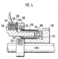
- Figure 4 shows a second
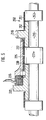
- Figure 5 shows a third embodiment.
- a hand-held power tool designed as a hammer drill has an outer housing 1, preferably made of plastic, to which a housing 2 for holding the internal components of the hammer drill is firmly connected.
- an electric motor 3 is housed, which is in gear connection with an intermediate shaft 4.
- the intermediate shaft 4 is in turn connected via a switching mechanism 5 to a hammer tube 6, on which a tool holder 7 is placed.
- a tool 8 can be inserted into the tool holder 7.
- a striking mechanism 10 which is known per se and is not shown in all details is driven by the intermediate shaft 4.
- FIG. 3 shows a reciprocatingly driven pot piston 11, a racket 12 guided therein and a striker 13 acted upon by the racket 12. The striker 13 exerts axial impacts on the shank of the tool 8 during operation.
- the intermediate shaft 4 which is roller-mounted in the housing, carries a pinion 15 and serves the switching mechanism 5 as a drive shaft.
- the hammer tube 6, which is non-rotatably connected to a gear 16, serves as the output shaft.
- the rear derailleur 5 has a drive hub 18 which meshes with the pinion 15.
- a gear shaft 19 is in constant engagement with the toothed wheel 16 of the hammer tube 6 with its toothing 20.
- the drive hub 18 is freely rotatable on the output hub 19.
- An output hub 21 is rotatably connected to the selector shaft 19.
- a switching spring 22 is looped under pre-tension, which non-positively connects the two hubs according to the principle of cable friction. Their winding direction corresponds to the direction of rotation of the drive hub 18.
- Drive hub 18, output hub 21 and shift spring 22 together form a switchable wrap spring clutch in the drive train between Electric motor 3 and tool holder 7.
- a radially outwardly protruding end 23 of the switching spring 22 engages in a recess 24 in a switching sleeve 25 surrounding the switching spring 22, so that the switching spring 22 is connected to the switching sleeve 25 in a form-fitting, rotationally fixed manner.
- the output hub 21 has a front hub section 27, against which the switching spring 22 rests, and a rear hub section 28, against which a brake spring 30, also designed as a wrap spring, bears under pretension.
- the brake spring 30 is additionally positively connected to the output hub 21 by its end 31 projecting inwards into the rear hub section 28. In axial extension to the output hub 21, this is followed by a housing hub 32, which, however, has a smaller outer diameter than the rear hub section 28.
- the output hub 21 and the selector shaft 19 are freely rotatable relative to the housing hub 32.
- the selector shaft 19 is rotatably mounted in the housing hub 32 and the housing 2 by means of needle bearings.
- the brake spring 30 surrounds the housing hub 32 without touching it.
- the housing-side end 33 of the brake spring 30 engages in a recess 34 in the switching sleeve 25.
- Output hub 21, brake spring 30 and housing hub 32 together form a switchable wrap spring clutch which, in the closed state (not shown), couples the selector shaft 19 and thus the tool 7 to the housing 2 in a rotationally fixed manner.
- An electromagnetic brake 36 is fastened in a rotationally fixed manner to the housing hub 32.
- the brake 36 has a coil 37 and a non-ferromagnetic brake plate 38 as a brake lining.
- the coil 37 can be energized via connection cable 39.
- the brake plate 38 lies with a small gap opposite a braking surface 40 on the switching sleeve 25.
- the housing hub 32 is in turn screwed to the housing 2.
- the entire switching mechanism 5 with its parts 18 to 40 forms a unit which can be inserted into the housing 2 like a cartridge and forms part of the drive train between the motor 3 and the tool holder 7 of the hammer drill 1.
- An overload detector (not shown) can be arranged on the electric motor 3, which causes the motor 3 to be switched off if the motor current is too high due to one of the clutches 18, 21, 22 or 21, 30, 32 slipping or closing.
- the intermediate shaft 4 is driven by the electric motor 3 in a constantly rotating manner.
- the rotary movement is transmitted to the drive hub 18 of the switching mechanism 5, which is also driven in a constantly rotating manner.
- the output hub 21 is non-positively connected to the drive hub 18 via the prestressed switching spring 22.
- the switching spring 22 wraps around both the outer diameter of the drive hub and the outer diameter of the driven hub 21 under pretension.
- the winding direction of the switching spring 22 is selected such that the rotation of the drive hub causes an increase in the contact pressure of the spring on the hubs.
- the rotary movement is transmitted from the output hub 21 to the gearwheel 16 of the hammer tube 6 via the selector shaft 19, which is firmly connected to it, and its toothing 20 and serves to drive the tool 8 in rotation.
- the switching sleeve 25 is also rotated continuously.
- the brake spring 30, which is preloaded on the rear hub section 28, is also rotated continuously. During normal operation, the brake spring 30 is not connected to the stationary housing hub 32.
- the switching sleeve 25 When the switching sleeve 25 is braked, it simultaneously rotates the brake spring 30 in the direction of its winding direction in such a way that the brake spring 30 positively engages the housing hub 32. As a result, the control shaft 19 connected to the tool is stopped in relation to the housing 2 in a short time. This means that the housing cannot turn around the tool 8 and slips out of the hand of the operator, but in most cases the hooked tool is torn away again from the masonry or the workpiece.
- the electric motor 3 can continue to run or run out and only drives the idling drive hub 18, which rotates with respect to the selector shaft 19.
- the rotary drive of the tool can also be switched off.
- the second exemplary embodiment according to FIG. 4 shows a series connection compared to the parallel connection of the wrap springs from the first exemplary embodiment. Components of the same type are identified by reference numbers increased by 100.
- the rear derailleur 105 has a drive hub 118 which is rotatably mounted on a selector shaft 119.
- An output hub 121 is non-rotatably connected to the selector shaft 119, in which a selector spring 122 engages in a form-fitting manner.
- the switching spring 122 wraps around the hub 121 on its circumference. In its further course, the switching spring 122 wraps around the drive hub 118.
- the second end 123 of the switching spring 122 projects into a transmission ring 100, into which an end 131 of a brake spring 130 also projects.
- the transmission ring 100 connects the two spring ends 123, 131 in a form-fitting manner.
- the second end 132 of the brake spring 130 is positively connected to a switching sleeve 125.
- a housing hub 132 projects into the interior of the brake spring 130 without touching the brake spring during the rotary drive of the tool holder (not shown in FIG. 4).
- An electromagnetic brake 136 with a coil 137 and a non-ferromagnetic brake plate 138 as a brake pad, which is opposite a braking surface 140 of the shift sleeve 125, is seated on the housing hub 132, which is firmly connected to the housing.
- brake 136 is triggered, as in the first exemplary embodiment, and brakes shift sleeve 125, which rotates during operation.
- the brake spring 130 and the transmission ring 100 are also braked with respect to the selector shaft 119.
- the brake spring 130 narrows and loops around the housing hub 132.
- the switching shaft 119 which is rotatably connected to the tool holder, is thus non-positively connected to the housing, so that the housing no longer rotates around the blocked tool can.
- the switching mechanism 205 is constructed in its core just like the first exemplary embodiment.
- the corresponding components are identified by reference numbers increased by 200.
- these are drive hub 218, selector shaft 219, output hub 221, selector spring 222, selector sleeve 225, brake spring 230, housing hub 232 and an electromagnetic brake 236.
- clutch 218, 221, 222 is also equipped with a freewheel lock 250.
- This consists of a further wrap spring 251, which is wound with a winding direction opposite to the switching spring 222 under pretension on the drive hub 218 and the switching shaft 219.
- the drive hub 218 carries an additional hub section 252 and the selector shaft 219 has an additional collar 253 with the same outer diameter as the hub section 252.
- This embodiment has the advantage that reverse torques which are introduced into the drive train by the tool can be transmitted from the wrap spring 251 to the selector shaft 219.
- the switching spring 222 would not be able to do this, since wrap springs can only transmit significant moments in one direction of rotation. If the brake 236 is triggered, the switching spring 222 is released as in the first exemplary embodiment, while the wrap spring 251 is subjected to the direction of rotation which transmits its moments and slips on the hub section 252 under the collar 253.
Landscapes
- Engineering & Computer Science (AREA)
- Mechanical Engineering (AREA)
- General Engineering & Computer Science (AREA)
- Physics & Mathematics (AREA)
- Electromagnetism (AREA)
- Percussive Tools And Related Accessories (AREA)
Claims (8)
- Machine électroportative à main, notamment perforateur comportant un axe de commutation (19) prévu dans la ligne de transmission entre un moteur (3) et un porte-outil (7), cet axe pouvant être couplé à un boîtier (2) de la machine électroportative par l'intermédiaire d'un ressort frein (30) d'un embrayage à ressort à boucle (21, 30, 32), une extrémité (33) du ressort frein (30) étant reliée solidairement en rotation à une douille de commutation (25) qui entraîne en rotation l'axe de commutation (19) lorsque la machine électroportative fonctionne normalement, et qui peut être freinée pour coupler l'embrayage à ressort enveloppe (31, 30, 32) à l'aide d'un frein électromagnétique (36) par rapport à l'axe de commutation (19), caractérisée en ce que l'action de freinage du frein électromagnétique (36) est activée par une installation de détection pour le cas du blocage de l'outil.
- Machine électroportative à main selon la revendication 1, caractérisée en ce que le frein électromagnétique (36) comporte une bobine (37) traversée par un courant électrique en cas de blocage.
- Machine électroportative à main selon la revendication 1 ou 2, caractérisée en ce que le ressort frein (30) entoure à l'état de freinage, la douille de commutation (25) au moins partiellement autour d'un moyeu (32) solidaire du boîtier.
- Machine électroportative à main selon l'une des revendications précédentes, caractérisée en ce que la surface du frein électromagnétique (36) qui coopère en alternance avec la douille de commutation (25) est munie d'une garniture de frein (38).
- Machine électroportative à main selon l'une des revendications précédentes, caractérisée en qu'à l'aide du frein électromagnétique (36) et de la douille de commutation (25), on actionne simultanément un embrayage de commutation (18, 21, 22) qui sépare l'axe de commutation (19) du moteur (3).
- Machine électroportative à main selon la revendication 5, caractérisée en ce que l'embrayage de commutation (18, 21, 22) est un embrayage à ressort à boucle comportant un ressort de commutation (22) dont une extrémité (23) pénètre dans une découpe (24) de la douille de commutation (25).
- Machine électroportative à main selon la revendication 6, caractérisée en ce que la machine électroportative à main est munie d'un verrou de roue libre (250) formée par un embrayage à ressort enveloppe (250, 251, 252) supplémentaire qui a un sens d'enroulement opposé à celui du ressort enveloppe (222) de l'embrayage à ressort enveloppe (218, 221, 222).
- Machine électroportative à main selon l'une des revendications précédentes, caractérisée en ce qu'elle comporte un détecteur de surcharge qui coupe le moteur (3) en cas de patinage de l'embrayage de commutation (18, 21, 22).
Applications Claiming Priority (2)
| Application Number | Priority Date | Filing Date | Title |
|---|---|---|---|
| DE4036911 | 1990-11-20 | ||
| DE4036911A DE4036911A1 (de) | 1990-11-20 | 1990-11-20 | Handwerkzeugmaschine mit bremskupplung |
Publications (2)
| Publication Number | Publication Date |
|---|---|
| EP0486843A1 EP0486843A1 (fr) | 1992-05-27 |
| EP0486843B1 true EP0486843B1 (fr) | 1995-01-18 |
Family
ID=6418595
Family Applications (1)
| Application Number | Title | Priority Date | Filing Date |
|---|---|---|---|
| EP91118288A Expired - Lifetime EP0486843B1 (fr) | 1990-11-20 | 1991-10-26 | Outil électro portatif avec embrayage-frein |
Country Status (2)
| Country | Link |
|---|---|
| EP (1) | EP0486843B1 (fr) |
| DE (2) | DE4036911A1 (fr) |
Cited By (2)
| Publication number | Priority date | Publication date | Assignee | Title |
|---|---|---|---|---|
| US9193055B2 (en) | 2012-04-13 | 2015-11-24 | Black & Decker Inc. | Electronic clutch for power tool |
| EP3266567A1 (fr) | 2016-07-06 | 2018-01-10 | HILTI Aktiengesellschaft | Machine-outil portative |
Families Citing this family (3)
| Publication number | Priority date | Publication date | Assignee | Title |
|---|---|---|---|---|
| DE19646381A1 (de) * | 1996-11-11 | 1998-05-14 | Hilti Ag | Handgerät |
| DE19646382A1 (de) * | 1996-11-11 | 1998-05-14 | Hilti Ag | Handgerät |
| EP0989323A3 (fr) * | 1998-09-25 | 2002-08-07 | Baumann Federn AG | Embrayage à ressort hélicoidal |
Family Cites Families (7)
| Publication number | Priority date | Publication date | Assignee | Title |
|---|---|---|---|---|
| US3228497A (en) * | 1963-12-09 | 1966-01-11 | Honeywell Inc | Spring coil clutch and electromagnetic brake |
| CH492597A (fr) * | 1967-10-09 | 1970-06-30 | Mowbot Inc | Dispositif de freinage et de débrayage à ressort |
| US3738461A (en) * | 1971-06-02 | 1973-06-12 | Maremont Corp | Neutral position clutch for spindle assembly |
| US4090802A (en) * | 1976-12-27 | 1978-05-23 | Otto Bilz Werkzeugfabrik | Radio detector for detecting dull and broken tools |
| EP0172457B1 (fr) * | 1984-08-16 | 1988-09-21 | Baumann & Cie. AG | Embrayage à ressort autoserreur |
| EP0303651B2 (fr) * | 1987-03-05 | 1999-12-01 | Robert Bosch Gmbh | Procede d'interruption de l'entrainement, en particulier en percussion et/ou en rotation, d'un outil a main |
| DE3731244A1 (de) * | 1987-09-17 | 1989-03-30 | Bosch Gmbh Robert | Handwerkzeugmaschine |
-
1990
- 1990-11-20 DE DE4036911A patent/DE4036911A1/de not_active Withdrawn
-
1991
- 1991-10-26 DE DE59104325T patent/DE59104325D1/de not_active Expired - Fee Related
- 1991-10-26 EP EP91118288A patent/EP0486843B1/fr not_active Expired - Lifetime
Cited By (4)
| Publication number | Priority date | Publication date | Assignee | Title |
|---|---|---|---|---|
| US9193055B2 (en) | 2012-04-13 | 2015-11-24 | Black & Decker Inc. | Electronic clutch for power tool |
| EP3266567A1 (fr) | 2016-07-06 | 2018-01-10 | HILTI Aktiengesellschaft | Machine-outil portative |
| WO2018007152A1 (fr) | 2016-07-06 | 2018-01-11 | Hilti Aktiengesellschaft | Machine-outil portative |
| US11027389B2 (en) | 2016-07-06 | 2021-06-08 | Hilti Aktiengesellschaft | Handheld power tool |
Also Published As
| Publication number | Publication date |
|---|---|
| EP0486843A1 (fr) | 1992-05-27 |
| DE4036911A1 (de) | 1992-05-21 |
| DE59104325D1 (de) | 1995-03-02 |
Similar Documents
| Publication | Publication Date | Title |
|---|---|---|
| EP0841126B1 (fr) | Appareil à main entraíné par moteur avec un dispositif de sécurité dans la cas d'outil de blocage | |
| EP0494379B1 (fr) | Outil à main avec embrayage de securité | |
| EP0841127B1 (fr) | Appareil à main entraíné par moteur avec un dispositif de sécurité dans le cas d'outil de blocage | |
| EP0303651B1 (fr) | Procede d'interruption de l'entrainement, en particulier en percussion et/ou en rotation, d'un outil a main | |
| EP0474651B1 (fr) | Marteau perforateur ou percuteur avec embrayage dans l'entrainement de la percussion | |
| EP0326783B1 (fr) | Outil à main actionné par moteur | |
| DE3830199C1 (fr) | ||
| EP0594690B1 (fr) | Dispositif pour la protection contre les surcharges et pour le freinage d'une piece de machine entrainee par un moteur | |
| DE10037808A1 (de) | Handwerkzeugmaschine | |
| EP0064763B1 (fr) | Commande, en particulier commande de déplacement dans un véhicule à moteur | |
| DE2522446C3 (de) | Sicherheitsrutschkupplung für Handbohrmaschine | |
| DE2165066A1 (de) | Schlagbohrmaschine | |
| EP1765556B1 (fr) | Marteau de percussion et/ou de perforation a accouplement de securite | |
| CH666945A5 (de) | Schlingfeder-kupplung. | |
| EP0486843B1 (fr) | Outil électro portatif avec embrayage-frein | |
| DE3707052A1 (de) | Verfahren zum unterbrechen der antriebstaetigkeit, insbesondere drehantriebstaetigkeit, einer handwerkzeugmaschine | |
| EP1576713A1 (fr) | Adaptateur, electroreducteur et boitier d'electroreducteur | |
| DE102009028151A1 (de) | Stellantrieb | |
| EP0486842A1 (fr) | Outil électro portatif | |
| CH432948A (de) | Sicherheitskupplung für Drehmomente übertragende Wellen | |
| DE4037909C2 (de) | Eilrücklauf-Vorrichtung für eine automatische Bohrmaschine | |
| DE102019126962B3 (de) | Elektromotorische Antriebseinheit für ein mit Muskelkraft antreibbares Fahrzeug und ein mit Muskelkraft antreibbares Fahrzeug | |
| WO1996018034A1 (fr) | Dispositif de demarrage destine a un moteur | |
| DE4026213A1 (de) | Klinkenfreilauf | |
| DE119088C (fr) |
Legal Events
| Date | Code | Title | Description |
|---|---|---|---|
| PUAI | Public reference made under article 153(3) epc to a published international application that has entered the european phase |
Free format text: ORIGINAL CODE: 0009012 |
|
| AK | Designated contracting states |
Kind code of ref document: A1 Designated state(s): CH DE FR GB IT LI |
|
| 17P | Request for examination filed |
Effective date: 19921017 |
|
| 17Q | First examination report despatched |
Effective date: 19930917 |
|
| GRAA | (expected) grant |
Free format text: ORIGINAL CODE: 0009210 |
|
| AK | Designated contracting states |
Kind code of ref document: B1 Designated state(s): CH DE FR GB IT LI |
|
| ET | Fr: translation filed | ||
| REF | Corresponds to: |
Ref document number: 59104325 Country of ref document: DE Date of ref document: 19950302 |
|
| ITF | It: translation for a ep patent filed | ||
| GBT | Gb: translation of ep patent filed (gb section 77(6)(a)/1977) |
Effective date: 19950327 |
|
| PLBE | No opposition filed within time limit |
Free format text: ORIGINAL CODE: 0009261 |
|
| STAA | Information on the status of an ep patent application or granted ep patent |
Free format text: STATUS: NO OPPOSITION FILED WITHIN TIME LIMIT |
|
| 26N | No opposition filed | ||
| PGFP | Annual fee paid to national office [announced via postgrant information from national office to epo] |
Ref country code: GB Payment date: 19981013 Year of fee payment: 8 |
|
| PGFP | Annual fee paid to national office [announced via postgrant information from national office to epo] |
Ref country code: FR Payment date: 19981021 Year of fee payment: 8 |
|
| PGFP | Annual fee paid to national office [announced via postgrant information from national office to epo] |
Ref country code: CH Payment date: 19981027 Year of fee payment: 8 |
|
| PGFP | Annual fee paid to national office [announced via postgrant information from national office to epo] |
Ref country code: DE Payment date: 19981230 Year of fee payment: 8 |
|
| PG25 | Lapsed in a contracting state [announced via postgrant information from national office to epo] |
Ref country code: GB Free format text: LAPSE BECAUSE OF NON-PAYMENT OF DUE FEES Effective date: 19991026 |
|
| PG25 | Lapsed in a contracting state [announced via postgrant information from national office to epo] |
Ref country code: LI Free format text: LAPSE BECAUSE OF NON-PAYMENT OF DUE FEES Effective date: 19991031 Ref country code: CH Free format text: LAPSE BECAUSE OF NON-PAYMENT OF DUE FEES Effective date: 19991031 |
|
| GBPC | Gb: european patent ceased through non-payment of renewal fee |
Effective date: 19991026 |
|
| REG | Reference to a national code |
Ref country code: CH Ref legal event code: PL |
|
| PG25 | Lapsed in a contracting state [announced via postgrant information from national office to epo] |
Ref country code: FR Free format text: LAPSE BECAUSE OF NON-PAYMENT OF DUE FEES Effective date: 20000630 |
|
| PG25 | Lapsed in a contracting state [announced via postgrant information from national office to epo] |
Ref country code: DE Free format text: LAPSE BECAUSE OF NON-PAYMENT OF DUE FEES Effective date: 20000801 |
|
| REG | Reference to a national code |
Ref country code: FR Ref legal event code: ST |
|
| PG25 | Lapsed in a contracting state [announced via postgrant information from national office to epo] |
Ref country code: IT Free format text: LAPSE BECAUSE OF NON-PAYMENT OF DUE FEES;WARNING: LAPSES OF ITALIAN PATENTS WITH EFFECTIVE DATE BEFORE 2007 MAY HAVE OCCURRED AT ANY TIME BEFORE 2007. THE CORRECT EFFECTIVE DATE MAY BE DIFFERENT FROM THE ONE RECORDED. Effective date: 20051026 |