EP0486842A1 - Outil électro portatif - Google Patents
Outil électro portatif Download PDFInfo
- Publication number
- EP0486842A1 EP0486842A1 EP91118287A EP91118287A EP0486842A1 EP 0486842 A1 EP0486842 A1 EP 0486842A1 EP 91118287 A EP91118287 A EP 91118287A EP 91118287 A EP91118287 A EP 91118287A EP 0486842 A1 EP0486842 A1 EP 0486842A1
- Authority
- EP
- European Patent Office
- Prior art keywords
- wrap spring
- clutch
- tool according
- spring
- hand tool
- Prior art date
- Legal status (The legal status is an assumption and is not a legal conclusion. Google has not performed a legal analysis and makes no representation as to the accuracy of the status listed.)
- Withdrawn
Links
Images


Classifications
-
- F—MECHANICAL ENGINEERING; LIGHTING; HEATING; WEAPONS; BLASTING
- F16—ENGINEERING ELEMENTS AND UNITS; GENERAL MEASURES FOR PRODUCING AND MAINTAINING EFFECTIVE FUNCTIONING OF MACHINES OR INSTALLATIONS; THERMAL INSULATION IN GENERAL
- F16D—COUPLINGS FOR TRANSMITTING ROTATION; CLUTCHES; BRAKES
- F16D27/00—Magnetically- or electrically- actuated clutches; Control or electric circuits therefor
- F16D27/10—Magnetically- or electrically- actuated clutches; Control or electric circuits therefor with an electromagnet not rotating with a clutching member, i.e. without collecting rings
- F16D27/105—Magnetically- or electrically- actuated clutches; Control or electric circuits therefor with an electromagnet not rotating with a clutching member, i.e. without collecting rings with a helical band or equivalent member co-operating with a cylindrical coupling surface
-
- B—PERFORMING OPERATIONS; TRANSPORTING
- B25—HAND TOOLS; PORTABLE POWER-DRIVEN TOOLS; MANIPULATORS
- B25B—TOOLS OR BENCH DEVICES NOT OTHERWISE PROVIDED FOR, FOR FASTENING, CONNECTING, DISENGAGING, OR HOLDING
- B25B23/00—Details of, or accessories for, spanners, wrenches, screwdrivers
- B25B23/14—Arrangement of torque limiters or torque indicators in wrenches or screwdrivers
- B25B23/141—Mechanical overload release couplings
-
- B—PERFORMING OPERATIONS; TRANSPORTING
- B25—HAND TOOLS; PORTABLE POWER-DRIVEN TOOLS; MANIPULATORS
- B25D—PERCUSSIVE TOOLS
- B25D16/00—Portable percussive machines with superimposed rotation, the rotational movement of the output shaft of a motor being modified to generate axial impacts on the tool bit
- B25D16/003—Clutches specially adapted therefor
-
- B—PERFORMING OPERATIONS; TRANSPORTING
- B25—HAND TOOLS; PORTABLE POWER-DRIVEN TOOLS; MANIPULATORS
- B25F—COMBINATION OR MULTI-PURPOSE TOOLS NOT OTHERWISE PROVIDED FOR; DETAILS OR COMPONENTS OF PORTABLE POWER-DRIVEN TOOLS NOT PARTICULARLY RELATED TO THE OPERATIONS PERFORMED AND NOT OTHERWISE PROVIDED FOR
- B25F5/00—Details or components of portable power-driven tools not particularly related to the operations performed and not otherwise provided for
- B25F5/001—Gearings, speed selectors, clutches or the like specially adapted for rotary tools
Definitions
- the invention is based on a handheld power tool according to the preamble of claim 1.
- a wrap spring clutch for switching the hammer mechanism of a hammer drill on or off or as a safety clutch for interrupting the rotary drive.
- wrap spring clutches as are also known from DE 37 31 244, are conventionally constructed symmetrically with two identical coupling halves.
- the hand tool according to the invention according to the characterizing features of the independent claims has the advantage that the coupling can be optimally adapted to the particular application in terms of easier shifting, a reduction in the range of the triggering torque or a change in the power density.
- Figure 1 shows an overall view of a rotary hammer
- Figure 2 shows a cross section along line II-II in Figure 1
- Figure 3 shows a partial section along line III-III in Figure 2.
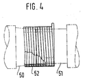
- Figure 4 shows a second embodiment of the invention with a different coupling geometry.
- a hand-held power tool designed as a hammer drill has an outer housing 1, preferably made of plastic, with which a housing 2 for holding the internal components of the hammer drill is firmly connected.
- an electric motor 3 is housed, which is in gear connection with an intermediate shaft 4.
- the intermediate shaft 4 is in turn via a switching mechanism 5 with a hammer tube 6 in gear connection, on which a tool holder 7 is placed.
- a tool 8 can be inserted into the tool holder 7.
- a striking mechanism 10 which is known per se and is not shown in all details is driven by the intermediate shaft 4.
- FIG. 3 shows a reciprocatingly driven pot piston 11, a racket 12 guided therein and a striker 13 acted upon by the racket 12.
- the striker 13 exerts axial impacts on the shank of the tool 8 during operation.
- the intermediate shaft 4, which is roller-mounted in the housing, carries a pinion 15 and serves the switching mechanism 5 as a drive shaft.
- the hammer tube 6, which is non-rotatably connected to a gear 16, serves as the output shaft.
- the rear derailleur 5 has a drive hub 18 which meshes with the pinion 15 and carries a friction surface 17.
- a gearshift shaft 19 with its toothing 20 is in constant engagement with the gear 16 of the hammer tube 6.
- the drive hub 18 is freely rotatable on the gearshift shaft 19.
- An output hub 21 is connected in a rotationally fixed manner to the selector shaft 19. This has a cylindrical front friction surface 27, which is shorter and has a larger outer diameter than the friction surface 17 of the drive hub 18.
- a tension spring 22 is wound around the two friction surfaces 17 and 27 under tension, which, according to the principle of cable friction, the two hubs 18 , 21 non-positively connects. Their winding direction corresponds to the direction of rotation of the drive hub 18.
- the second coupling half of the safety clutch consists of the driven hub 21 and the part of the switching spring 22 that wraps around it.
- the output hub 21 has, in addition to the front friction surface 27 on which the switching spring 22 rests, a rear friction surface 28 on which, as a second example of an asymmetrical wrap spring clutch, a brake spring 30 rests under prestress.
- the brake spring 30 is additionally positively connected to the output hub 21 by its end 31 projecting inwards into the rear friction surface 28.
- An axial extension of the output hub 21 is followed by a housing hub 32. This forms a friction surface with a smaller outer diameter and a greater length than the rear friction surface 28.
- the output hub 21 and the shift shaft 19 are freely rotatable relative to the housing hub 32.
- the selector shaft 19 is rotatably supported in the housing hub 32 and the housing 2 by means of needle bearings.
- the brake spring 30 surrounds the housing hub 32 without pretensioning and without touching it.
- the housing-side end 33 of the brake spring 30 engages in a recess 34 in the switching sleeve 25.
- the friction surface 28 on the output hub 21, the brake spring 30 and the housing hub 32 together form a second asymmetrical wrap spring clutch which is switchable and, in the closed state (not shown), couples the control shaft 19 and thus the tool 7 to the housing 2 in a rotationally fixed manner.
- An electromagnetic brake 36 is fastened in a rotationally fixed manner to the housing hub 32.
- the brake 36 has a coil 37 and a brake plate 38 as a brake lining.
- the coil 37 can be energized via connection cable 39.
- the brake plate 38 lies opposite a brake surface 40 on the shift sleeve 25 with a small gap.
- the housing hub 32 is in turn screwed to the housing 2.
- the entire switching mechanism 5 with its parts 18 to 40 forms a unit which can be inserted into the housing 2 like a cartridge and forms part of the drive train between the motor 3 and the tool holder 7 of the hammer drill 1.
- the couplings 17, 21, 22 and 21, 30, 32 each have asymmetrical coupling halves. That is, either the two friction surfaces a coupling are geometrically different and / or the wrap spring has two different halves.
- the wrap spring can rest on the two friction surfaces with a different wrap angle or with different pretension, or the spring wire thickness can be different.
- the inside diameter of the wrap spring can be varied.
- the friction surfaces on the other hand, can differ in terms of their axial length, their diameter, their taper or their coefficient of friction. Optimizing the friction surface geometry can increase the power density, among other things.
- the smaller wrap angle on the friction surface 27 is compensated for by a higher pretensioning of the associated wrap spring half.
- This has the advantage that the actuating force for releasing the wrap spring 22 on the side of the drive hub 18 is low because of the high number of turns.
- the clutch thus shifts faster than a symmetrical design when actuated by friction.
- the low number of turns on the output hub 21, on the other hand means that the upper limit of the transmissible torque M T can be more precisely determined.
- the range of the transmissible torque with constant fluctuation in the coefficient of friction is smaller, the smaller the wrap angle ⁇ of the wrap spring 22.
- the length of the coupling 28, 30, 32 can be reduced in that a spring end 31 is positively connected to the friction surface 28, which also serves to center the wrap spring 30. This is then only rotatable relative to the other, the friction surface of the housing hub 32 or can slide on it.
- the intermediate shaft 4 is driven by the electric motor 3 in a constantly rotating manner. Via the pinion 15 of the intermediate shaft, the rotary movement is transmitted to the drive hub 18 of the switching mechanism 5, which is also driven in a constantly rotating manner.
- the output hub 21 is non-positively connected to the drive hub 18 via the prestressed switching spring 22.
- the switching spring 22 wraps around both the friction surface 17 of the drive hub and the friction surface 27 of the output hub 21 under prestress.
- the winding direction of the switching spring 22 is selected such that the rotation of the drive hub causes an increase in the contact pressure of the spring on the hubs.
- the rotational movement is transmitted from the output hub 21 to the gearwheel 16 of the hammer tube 6 via the selector shaft 19, which is firmly connected to it, and its toothing 20 and serves to drive the tool 8 in rotation.
- the switching sleeve 25 is also rotated continuously.
- the brake spring 30, which is preloaded on the rear friction surface 28, is also rotated continuously. During normal operation, the brake spring 30 is not connected to the stationary housing hub 32.
- a blocking of the tool 8 in the workpiece, ie a sudden braking of the tool and jerky acceleration of the housing 1, 2 is detected by a detection device, not shown in detail.
- the attraction of the rotating switching sleeve 25 caused by the electromagnet 37 causes it to be braked.
- the brake plate 38 serves as a wear surface.
- the braked switching sleeve 25 rotates the end 23 of the switching spring 22 against its winding sense, so that the non-positive connection of the switching spring 22 to the hubs 18, 21 is canceled.
- the switching sleeve 25 rotates the brake spring 30 in the direction of its winding direction in such a way that the brake spring 30 non-positively engages the housing hub 32 and thus also prevents a further rotary drive of the tool 8.
- the control shaft 19 connected to the tool is shut down in relation to the housing 2 in a short time.
- the housing cannot rotate around the tool 8 and slips out of the hand of the operator.
- the electric motor 3 can continue to run or run out and only drives the idling drive hub 18, which rotates relative to the selector shaft 19.
- FIG. 4 only two coupling hubs 50, 51 and a wrap spring 52 shown in the relaxed state are shown schematically.
- the hub 51 is cylindrical, the hub 50 is conical.
- the wrap spring 52 lies against the conical hub 50 under increased pretension.
- the same effect can also be achieved by conically configuring the wrap spring.
- the wrap spring 52 has a constant inner diameter. Their wrap angle is smaller on the conical hub 50 than on the hub 51.
- the spring wire width increases towards the hub separation point. This has the advantage that the strength of the wrap spring 52 is highest at the point of greatest stress.
Landscapes
- Engineering & Computer Science (AREA)
- Mechanical Engineering (AREA)
- General Engineering & Computer Science (AREA)
- Physics & Mathematics (AREA)
- Electromagnetism (AREA)
- Percussive Tools And Related Accessories (AREA)
Applications Claiming Priority (2)
| Application Number | Priority Date | Filing Date | Title |
|---|---|---|---|
| DE4036912 | 1990-11-20 | ||
| DE19904036912 DE4036912A1 (de) | 1990-11-20 | 1990-11-20 | Handwerkzeugmaschine |
Publications (1)
| Publication Number | Publication Date |
|---|---|
| EP0486842A1 true EP0486842A1 (fr) | 1992-05-27 |
Family
ID=6418596
Family Applications (1)
| Application Number | Title | Priority Date | Filing Date |
|---|---|---|---|
| EP91118287A Withdrawn EP0486842A1 (fr) | 1990-11-20 | 1991-10-26 | Outil électro portatif |
Country Status (2)
| Country | Link |
|---|---|
| EP (1) | EP0486842A1 (fr) |
| DE (1) | DE4036912A1 (fr) |
Cited By (3)
| Publication number | Priority date | Publication date | Assignee | Title |
|---|---|---|---|---|
| WO1992018784A1 (fr) * | 1991-04-18 | 1992-10-29 | The Ingersoll-Rand Company | Accouplement par ressort enroule pour appareil a percussion |
| EP0724934A1 (fr) * | 1995-01-31 | 1996-08-07 | Hitachi Koki Co., Ltd. | Tournevis motorisé et mécanisme d'embrayage utilisé dans celui-ci |
| DE19540718B4 (de) * | 1995-11-02 | 2007-04-05 | Robert Bosch Gmbh | Handwerkzeugmaschine mit einer von einer Detektionseinrichtung auslösbaren Blockiereinrichtung |
Families Citing this family (1)
| Publication number | Priority date | Publication date | Assignee | Title |
|---|---|---|---|---|
| DE29701358U1 (de) * | 1997-01-29 | 1997-04-17 | Lässig, Lothar, 08324 Bockau | Elektrowerkzeugmaschine |
Citations (5)
| Publication number | Priority date | Publication date | Assignee | Title |
|---|---|---|---|---|
| DE1196026B (de) * | 1960-09-30 | 1965-07-01 | Thaelmann Schwermaschbau Veb | Mechanisch schaltbare Federbandkupplung |
| US3228497A (en) * | 1963-12-09 | 1966-01-11 | Honeywell Inc | Spring coil clutch and electromagnetic brake |
| US3726372A (en) * | 1971-10-27 | 1973-04-10 | Warner Electric Brake & Clutch | Helical spring clutch |
| WO1988006508A2 (fr) * | 1987-03-05 | 1988-09-07 | Robert Bosch Gmbh | Procede d'interruption de l'entrainement, en particulier en percussion et/ou en rotation, d'un outil a main |
| DE3731244A1 (de) * | 1987-09-17 | 1989-03-30 | Bosch Gmbh Robert | Handwerkzeugmaschine |
-
1990
- 1990-11-20 DE DE19904036912 patent/DE4036912A1/de not_active Withdrawn
-
1991
- 1991-10-26 EP EP91118287A patent/EP0486842A1/fr not_active Withdrawn
Patent Citations (5)
| Publication number | Priority date | Publication date | Assignee | Title |
|---|---|---|---|---|
| DE1196026B (de) * | 1960-09-30 | 1965-07-01 | Thaelmann Schwermaschbau Veb | Mechanisch schaltbare Federbandkupplung |
| US3228497A (en) * | 1963-12-09 | 1966-01-11 | Honeywell Inc | Spring coil clutch and electromagnetic brake |
| US3726372A (en) * | 1971-10-27 | 1973-04-10 | Warner Electric Brake & Clutch | Helical spring clutch |
| WO1988006508A2 (fr) * | 1987-03-05 | 1988-09-07 | Robert Bosch Gmbh | Procede d'interruption de l'entrainement, en particulier en percussion et/ou en rotation, d'un outil a main |
| DE3731244A1 (de) * | 1987-09-17 | 1989-03-30 | Bosch Gmbh Robert | Handwerkzeugmaschine |
Non-Patent Citations (2)
| Title |
|---|
| PATENT ABSTRACTS OF JAPAN vol. 10, no. 365 (M-542)(2422) 6. Dezember 1986 & JP-A-61 160 633 ( NIPPON ) 27. Juli 1986 * |
| PATENT ABSTRACTS OF JAPAN vol. 9, no. 11 (M-351)(1734) 18. Januar 1985 & JP-A-59 159 425 ( TOKYO DENKI K.K. ) 10. September 1984 * |
Cited By (3)
| Publication number | Priority date | Publication date | Assignee | Title |
|---|---|---|---|---|
| WO1992018784A1 (fr) * | 1991-04-18 | 1992-10-29 | The Ingersoll-Rand Company | Accouplement par ressort enroule pour appareil a percussion |
| EP0724934A1 (fr) * | 1995-01-31 | 1996-08-07 | Hitachi Koki Co., Ltd. | Tournevis motorisé et mécanisme d'embrayage utilisé dans celui-ci |
| DE19540718B4 (de) * | 1995-11-02 | 2007-04-05 | Robert Bosch Gmbh | Handwerkzeugmaschine mit einer von einer Detektionseinrichtung auslösbaren Blockiereinrichtung |
Also Published As
| Publication number | Publication date |
|---|---|
| DE4036912A1 (de) | 1992-05-21 |
Similar Documents
| Publication | Publication Date | Title |
|---|---|---|
| DE3931329C1 (fr) | ||
| EP1307313B1 (fr) | Machine portable | |
| DE3205141C2 (fr) | ||
| DE19900882A1 (de) | Handwerkzeugmaschine | |
| DE2252951B2 (de) | Bohrhammer | |
| DE3802740A1 (de) | Motorisch betriebenes handgeraet | |
| CH669756A5 (fr) | ||
| CH637056A5 (de) | Bohr- oder schlaghammer. | |
| EP0064763B1 (fr) | Commande, en particulier commande de déplacement dans un véhicule à moteur | |
| EP1765556B1 (fr) | Marteau de percussion et/ou de perforation a accouplement de securite | |
| DE69102308T2 (de) | Flanschbefestigungsvorrichtung. | |
| DE2165066A1 (de) | Schlagbohrmaschine | |
| DE2522446B2 (de) | Sicherungsrutschkupplung für Handbohrmaschine | |
| CH666945A5 (de) | Schlingfeder-kupplung. | |
| EP0040261A1 (fr) | Outil électrique avec engrenage à deux pas | |
| EP0486842A1 (fr) | Outil électro portatif | |
| DE1703846B2 (de) | Motorabschalteinrichtung an einem drehschlagschrauber | |
| DE4322540C2 (de) | Kugelgewindetrieb | |
| EP0486843B1 (fr) | Outil électro portatif avec embrayage-frein | |
| DE3730939A1 (de) | Motoranlassergetriebe | |
| EP1224403B1 (fr) | Double embrayage dote d'un electroaimant | |
| DE3430376A1 (de) | Lamellenkupplung fuer motorraeder und andere fahrzeuge | |
| DE3241863C2 (fr) | ||
| DE2759136A1 (de) | Kurbeltrieb fuer motorisch angetriebene, schlagend wirkende arbeitsgeraete | |
| EP0266531A2 (fr) | Equipement moteur |
Legal Events
| Date | Code | Title | Description |
|---|---|---|---|
| PUAI | Public reference made under article 153(3) epc to a published international application that has entered the european phase |
Free format text: ORIGINAL CODE: 0009012 |
|
| AK | Designated contracting states |
Kind code of ref document: A1 Designated state(s): CH DE FR GB IT LI |
|
| 17P | Request for examination filed |
Effective date: 19921017 |
|
| 17Q | First examination report despatched |
Effective date: 19930903 |
|
| STAA | Information on the status of an ep patent application or granted ep patent |
Free format text: STATUS: THE APPLICATION IS DEEMED TO BE WITHDRAWN |
|
| 18D | Application deemed to be withdrawn |
Effective date: 19941104 |