EP0486852B1 - Appareil de formation d'images avec dispositif de reliure - Google Patents
Appareil de formation d'images avec dispositif de reliure Download PDFInfo
- Publication number
- EP0486852B1 EP0486852B1 EP91118434A EP91118434A EP0486852B1 EP 0486852 B1 EP0486852 B1 EP 0486852B1 EP 91118434 A EP91118434 A EP 91118434A EP 91118434 A EP91118434 A EP 91118434A EP 0486852 B1 EP0486852 B1 EP 0486852B1
- Authority
- EP
- European Patent Office
- Prior art keywords
- binding
- malfunction
- unit
- image forming
- binding unit
- Prior art date
- Legal status (The legal status is an assumption and is not a legal conclusion. Google has not performed a legal analysis and makes no representation as to the accuracy of the status listed.)
- Expired - Lifetime
Links
- 230000007257 malfunction Effects 0.000 claims description 26
- 239000011230 binding agent Substances 0.000 claims description 22
- 238000000034 method Methods 0.000 claims description 21
- 230000008569 process Effects 0.000 claims description 16
- 238000010438 heat treatment Methods 0.000 claims description 15
- 238000001514 detection method Methods 0.000 claims description 12
- 238000001816 cooling Methods 0.000 claims description 11
- 230000004044 response Effects 0.000 claims description 5
- 239000012790 adhesive layer Substances 0.000 claims description 4
- 239000004973 liquid crystal related substance Substances 0.000 description 10
- 230000005856 abnormality Effects 0.000 description 3
- 239000000853 adhesive Substances 0.000 description 3
- 230000001070 adhesive effect Effects 0.000 description 3
- 230000003287 optical effect Effects 0.000 description 3
- 239000003990 capacitor Substances 0.000 description 2
- 230000008859 change Effects 0.000 description 2
- 238000010586 diagram Methods 0.000 description 2
- 230000004048 modification Effects 0.000 description 2
- 238000012986 modification Methods 0.000 description 2
- 238000003825 pressing Methods 0.000 description 2
- 230000002159 abnormal effect Effects 0.000 description 1
- 230000003213 activating effect Effects 0.000 description 1
- 238000004140 cleaning Methods 0.000 description 1
- 238000005520 cutting process Methods 0.000 description 1
- 230000007547 defect Effects 0.000 description 1
- 230000002950 deficient Effects 0.000 description 1
- 238000007599 discharging Methods 0.000 description 1
- 238000005286 illumination Methods 0.000 description 1
- 230000001788 irregular Effects 0.000 description 1
- 239000000463 material Substances 0.000 description 1
- 238000002844 melting Methods 0.000 description 1
- 230000008018 melting Effects 0.000 description 1
- 230000001105 regulatory effect Effects 0.000 description 1
- 238000000926 separation method Methods 0.000 description 1
- 238000003860 storage Methods 0.000 description 1
- 229920005992 thermoplastic resin Polymers 0.000 description 1
Images



Classifications
-
- G—PHYSICS
- G03—PHOTOGRAPHY; CINEMATOGRAPHY; ANALOGOUS TECHNIQUES USING WAVES OTHER THAN OPTICAL WAVES; ELECTROGRAPHY; HOLOGRAPHY
- G03G—ELECTROGRAPHY; ELECTROPHOTOGRAPHY; MAGNETOGRAPHY
- G03G15/00—Apparatus for electrographic processes using a charge pattern
-
- B—PERFORMING OPERATIONS; TRANSPORTING
- B42—BOOKBINDING; ALBUMS; FILES; SPECIAL PRINTED MATTER
- B42C—BOOKBINDING
- B42C9/00—Applying glue or adhesive peculiar to bookbinding
- B42C9/0056—Applying glue or adhesive peculiar to bookbinding applying tape or covers precoated with adhesive to a stack of sheets
Definitions
- the present invention relates generally to an image forming apparatus, and particularly to an image forming apparatus having a binding unit
- Japanese Utility Model Laying-Open No. 41261/1986 discloses a copying machine provided with a binding device adjacent to the heating rollers of its fixing unit. In this copying machine, discharged sheets of paper are bound by utilizing the heat generated from the fixing unit.
- Japanese Utility Model Laying-Open No. 121456/1986 discloses another copying machine with a binding device incorporated in a sorter provided adjacent to the copying machine body. In this copying machine, copy-processed sheets discharged from the body are received and bound by the binding device.
- Such conventional image forming apparatuses having a binding function do not have any means of handling malfunctions which might occur during operation of the binding device.
- the United States Patent US-A-4 901 994 discloses a copying apparatus having a sorter with a sheet stapling function.
- the sorter comprises a plurality of bins for storing sorted sheets therein and stapling means disposed below the plurality of bins. Means are provided for activating the stapling means and for detecting the stapled sheets to be discharged from the stapling means.
- the European patent application EP-A-0 334 261 discloses an electrically heated binder apparatus in which a booklet of sheets is bound in a binder cover by means of electrically induced heating of an adhesive.
- the binder apparatus comprises electrical contacts which make electrical connection to the binder spine for providing electrical power to heat the adhesive.
- One object of the present invention is to enable an image-forming apparatus equipped of a binding means to respond to malfunctions which may arise during the operation of the binding means.
- Another object is to facilitate the detection of operational malfunctions in the binding means of an image forming apparatus capable of performing a binding function.
- an image forming apparatus including a binding unit is provided as defined in claim 1.
- a malfunction detector detects any malfunction which may occur in the binding unit.
- the binding operation shutoff interrupts the operation of the binding unit wherein the trouble occurred.
- Figs. 2 and 3 show a copying machine according to an embodiment of the present invention.
- a copying machine body 1 includes an original support 2 in its upper surface, and an original cover 3 is openably disposed on the original support 2.
- a feed tray 4 and a feed cassette 5 are detachably mounted on the right of the body 1 in the figures.
- a copy tray 6 is disposed into which copy-processed sheets are discharged.
- An optical exposure system 7 for reading an original is provided in an upper portion of the interior of the copying machine body 1.
- This optical exposure system 7 includes a light source and mirrors.
- An image forming unit 8 is provided in a central portion of the copying machine body 1.
- a photoconductive drum 9 on which an electrostatic latent image is formed is disposed at the center of the image forming unit 8.
- a main charger 10, a developing unit 11, a transfer charger 12, a separation charger 13, a cleaning unit 14 and related elements are disposed surrounding the photoconductive drum 9.
- a sheet transporting path 15 including a plurality of transport rollers extends from the feed tray 4 and feed cassette 5 to the image forming unit 8.
- a sheet discharging system 16 and a fixing unit 17 are provided between the image forming unit 8 and the copy tray 6.
- a binding unit 30 is provided in a right upper portion interiorly of the body 1, adjacent to the image forming unit 8.
- the binding unit 30 includes a container 31 which opens in a side wall 1a of the body 1 and extends obliquely downward from the side wall 1a.
- the opening of the container 31 is shut by a cover 32.
- the cover 32 is openable on a hinge 33 along its upper end.
- a pair of electrodes 34 for supplying electric power to a binder cover (described afterwards) is provided on the inner bottom surface of the container 31.
- a control circuit 35 shown in Fig. 5 controls the binding unit 30.
- a +24V power source is connected to one of the two electrodes 34.
- An oscillating circuit 41 is connected between the +24V power supply and the electrode 34 through a capacitor 40.
- a storage capacitor 42 for storing electric charge is also connected therebetween.
- the collector of a power transistor 43 is connected to the other of the two electrodes 34.
- the emitter of the power transistor 43 is grounded through a resistor 44.
- the base of the power transistor 43 is connected to the output terminal of a comparator 45.
- the non-inverting terminal of the comparator 45 is connected to a remote terminal 46.
- the inverting terminal of the comparator 45 is connected with the emitter of the power transistor 43 through a resistor 45a.
- a malfunction detecting circuit 47 and a start detection circuit 48 are provided between the power transistor 43 and the latter of the two electrodes 34.
- the trouble detecting circuit 47 includes a pair of comparators 49 and 50, and generates a high level output at an NG terminal 51 only when the collector voltage of the power transistor 43 is within a prescribed normal range. This normal range is defined by values of voltages applied to the input terminals of the comparators 49 and 50. The voltage values are fixed by voltage-dividing resistors 47a, 47b and 47c.
- the malfunction detecting circuit 47 generates a low level output upon detection of any malfunction in a binding operation, such as an abnormal value of the resistance of the electric heater in a binder cover (described afterwards), or a defect in the electrical contact made with the electrodes 34.
- the start detecting circuit 48 includes a comparator 52, and generates a high level output at a start terminal 53 upon detection of an increase in the collector voltage of the power transistor 43.
- an operation panel 20 is provided on the right front corner of the upper surface of the copying machine body 1.
- the operation panel 20 includes a liquid crystal display (LCD) 21 for displaying operation conditions, such as the number of copies and the operation time, in alphanumeric characters.
- the operation panel 20 further includes a print key 22 for instructing copy start, a ten-key board 23 for designating the number of copies, a heating-state lamp 24 for indicating a heating state of the binding unit 30, and a cooling-state lamp 25 for indicating a cooling state thereof.
- the print key 22 contains an LED which is illuminated when the copy operation is enabled.
- the lamps 24 and 25 each contain both a blue LED and a red LED.
- a control unit 60 as shown in Fig. 4 is provided in the copying machine according to the present embodiment.
- the control unit 60 includes a microcomputer consisting of a CPU, a ROM, a RAM and other related devices.
- the control unit 60 contains an I/O port 61 connected with the image forming unit 8, the liquid crystal display 21, the print key 22, the heating-state lamp 24, the cooling-state lamp 25 and with miscellaneous inputs and outputs. Further connected with the I/O port 61 are the remote terminal 46, the NG terminal 51 and the start terminal 53 of the control circuit 35 to the binding unit 30, and a buzzer 26 which is activated in response to the detection of a malfunction.
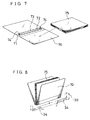
- a binder cover 70 as shown in Fig. 7 is used in the binding operation of this embodiment.
- the binder cover 70 includes an electric heater 72 and an adhesive layer 73 on the inner surface of its spine 71.
- the adhesive layer 73 consists, for example, of thermoplastic resin. Electrodes 74 of a pair are disposed on either end of the electric heater 72. The electrodes 74 are exposed in the outer surface (lower surface in the figure) of the spine 71.
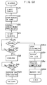
- step S1 an initialization procedure is carried out wherein, for example, a prescribed temperature for the fixing unit 17 is set.
- the LED of the print key 22 is activated.
- the program determines at step S2 whether the operator has commanded a copying operation by pressing the print key 22. If no command has been received, the program proceeds to step S3 and determines whether the copying machine is in its binding mode by reference to a signal from the start terminal 53. If the copying machine is not in the binding mode, the program proceeds to step S4. At step S4, it is determined whether the ten-key board 23 has been pressed to designate a given number of copies. Then, other processes of the copying machine are performed at step S21, and the program returns to step S2.
- step S4 the program proceeds from step S4 to step S5 and stores the input numerical value as the number of copies.
- step S6 the number of copies is displayed on the liquid crystal display 21. Then the program returns to the main routine.
- step S7 If the print key 22 is pressed, the program proceeds from step S2 to step S7. At step S7, "1" is subtracted from the copy number and the value obtained by the subtraction is indicated on the liquid crystal display 21. At step S8, the copying operation starts.
- step S9 it is determined at step S9 whether the subtracted copy number is "0" or not. If it is not zero, steps S7 and S8 are executed again in order to continue the copying process. If the determination at step S9 is "Yes", the program returns to the main routine of the control process.
- the sheets 75 are placed in a binder cover 70 and the binder cover 70 is folded, as shown in Figs. 7 and 8, wherein one side of the stack of sheets 75 makes contact with the adhesive material 73 on the spine 71.
- the binder cover 70 is then loaded into the container 31, pressing against the cover 32 as shown in Fig. 9.
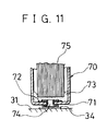
- the binder cover 70 reaches the bottom of the container 31 as shown in Figs. 10 and 11, the pair of electrodes 34 are brought into electrical connection with the electric heater 72 of the binder 70 through the electrodes 74.
- the start terminal 53 generates a high output when the pair of electrodes 34 comes into contact with the electrodes 74, since the potential at the non-inverting terminal of the comparator 52 of the start detecting circuit 48 increases.
- the program in the control unit 60 proceeds from step S3 to step S10 (Fig. 6A), executing a binding mode subroutine.
- a timer starts at step S11.
- the liquid crystal display 21 is activated, indicating the time remaining for the binding operation.
- the blue element of the heating-state lamp 24 is illuminated.
- the print key 22 is deactivated.
- the remote terminal 46 of the binding unit 30 generates a high input, whereby the power transistor 43 switches on allowing electric current to flow between the electrodes 34. Consequently, the electric heater 72 of the binder cover 70 heats, melting the adhesive layer 73 which thus adheres the side of the stack of sheets 75 to the binder cover 70.
- the power supplied to the electric heater 72 is regulated by the feedback circuit which includes the resistor 45a to the comparator 45. If any abnormality, such as an irregular resistance value of the electric heater 72 or a defective contact between the binder cover 70 and the electrodes 34 exists, the malfunction detecting circuit 47 will detect it. More specifically, when the collector potential of the power transistor 43 is outside the normal range defined by the comparator pair 49 and 50, the output from the NG terminal 51 drops. The change of output at the NG terminal 51 is detected at step S15 of Fig. 6B.
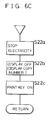
- step S16a a low output is induced in the remote terminal 46, thereby cutting off the power to the binding unit 30.
- step S16b "ERROR" is shown on the liquid crystal display 21.
- step S16c both the heating display lamp 24 and the cooling display lamp 25 illuminate in red.
- step S16d the buzzer 26 is activated.
- step S15 it is determined whether a predetermined interval required for the heating process has elapsed by reference to the time measured by the timer activated at step S11. If the interval has not elapsed, the program returns to step S15. If the predetermined heating interval time has elapsed, the program proceeds from step S17 to step S18, executing a cooling process. This process cuts off the power supply to the electrodes 34, switches off the heating-state lamp 24, and switches on the blue element of cooling-state lamp 25. Thus the process clearly apprises the operator that the binding unit 30 has been brought into a cooling state.
- step S19 the program pauses until the predetermined cooling time has elapsed.
- the program proceeds to step S20, turning off the time display on the liquid crystal display 21 and turning off the cooling-state lamp 25. In consequence, the liquid crystal display 21 returns to displaying the copy number, and the print key 22 is illuminated.
- step S20 the program returns to the main routine shown in Fig. 6A.
- the binder cover 70 may be withdrawn from the binding unit 30 after the illumination of the cooling-state lamp 25 at step S15 of Fig. 6B.
- a successive binding operation may be started utilizing another binder cover 70, whereby binding operations can be performed in succession for a large number of binder covers 70, at short intervals between the heating processes.
- a reset button not shown, must be pressed to restart the program, whereby the program is then forced to return to the main routine of Fig. 6A.
- step S22b may be replaced by step S16c so that the operator would be informed when trouble occurs in the binding unit 30.
Landscapes
- Physics & Mathematics (AREA)
- General Physics & Mathematics (AREA)
- Control Or Security For Electrophotography (AREA)
- Paper Feeding For Electrophotography (AREA)
- Folding Of Thin Sheet-Like Materials, Special Discharging Devices, And Others (AREA)
Claims (18)
- Appareil de formation d'images comprenant un dispositif (8) pour former des images sur des feuilles et un dispositif (30) pour relier les feuilles, dans lequel
ledit dispositif de reliure (30) est disposé adjacent audit dispositif de formation d'images (8) à l'intérieur du corps (1) de l'appareil de formation d'images et est adapté pour relier des feuilles dans un couvercle de reliure (70) au moyen d'un chauffage induit électriquement d'une couche adhésive (73) dans le dos (71) du couvercle de reliure (70);
ledit dispositif de reliure (30) comprend un récipient (31), dont la surface intérieure du fond est prévue avec des électrodes (34) pour fournir du courant électrique;
ledit appareil comprend en outre des moyens de détection (47) pour détecter un défaut de fonctionnement dans le fonctionnement dudit dispositif de reliure (30); et
des moyens d'indication (21, 24, 25, 26) sensibles aux moyens de détection (47) pour indiquer un défaut de fonctionnement détecté. - Appareil selon la revendication 1, dans lequel lesdits moyens indicateurs de défauts de fonctionnement comprennent un indicateur d'état de reliure (24, 25).
- Appareil selon la revendication 2, dans lequel ledit indicateur d'état de reliure comprend un indicateur de chauffage (24) pour indiquer un état de chauffage dudit dispositif de reliure (30) et un indicateur de refroidissement (25) pour indiquer un état de refroidissement de ce dispositif.
- Appareil selon la revendication 3, dans lequel ledit indicateur de chauffage (24) et ledit indicateur de refroidissement (25) sont chacun capables d'être éclairés à la fois en bleu et en rouge.
- Appareil selon l'une des revendications 1 à 4, dans lequel lesdits moyens indicateurs de défauts de fonctionnement comprennent un affichage alphanumérique (21) de l'appareil de formation d'images.
- Appareil selon l'une des revendications 1 à 5, comprenant en outre un moyen d'interruption (46) pour interrompre le fonctionnement dudit dispositif de reliure (30) en réponse à la détection du défaut de fonctionnement par lesdits moyens détecteurs de défauts de fonctionnement (47).
- Appareil selon la revendication 6, dans lequel ledit moyen d'interruption (46) interrompt également le fonctionnement de formation d'images dudit dispositif de formation d'images (8) en réponse à la détection du défaut de fonctionnement par lesdits moyens détecteurs de défauts de fonctionnement (47).
- Appareil selon l'une des revendications 1 à 7, dans lequel lesdits moyens détecteurs de défauts de fonctionnement (47) comprennent deux comparateurs (49, 50) pour définir une plage normale d'opérations de reliure par des valeurs de tension d'entrée au niveau de bornes d'entrée des comparateurs (49, 50).
- Appareil selon la revendication 8, dans lequel lesdits moyens détecteurs de défauts de fonctionnement (47) détectent un défaut de fonctionnement dans la valeur de résistance ou le contact d'électrode dudit dispositif de reliure (30).
- Appareil selon l'une des revendications 1 à 9, comprenant en outre des moyens de commande (35, 60) pour commander ledit dispositif de reliure (30).
- Appareil selon la revendication 10, dans lequel lesdits moyens de commande (35, 60) comprennent un circuit détecteur de début de reliure (48) pour détecter le début d'une opération de reliure.
- Appareil selon la revendication 11, dans lequel ledit Circuit détecteur de début de reliure (48) comprend un comparateur (52) pour détecter le début d'une opération de reliure par ledit dispositif de reliure (30).
- Appareil selon la revendication 11, dans lequel lesdits moyens de commande (35, 60) comprennent en outre des moyens de mesure du temps de reliure (S11) qui démarrent en réponse à la détection du début d'une opération de reliure par ledit circuit détecteur de début de reliure (48).
- Appareil selon la revendication 10, dans lequel lesdits moyens de commande (35, 60) comprennent un affichage (21) pour afficher le temps restant jusqu'à ce que soit atteinte la fin d'une opération de reliure.
- Appareil selon l'une des revendications 10 à 14, dans lequel la commande dudit dispositif de reliure (30) par lesdits moyens de commande (35, 60) procure une période de chauffage et une période de refroidissement pendant une opération de reliure.
- Appareil selon la revendication 6 ou la revendication 7, dans lequel ledit moyen d'interruption (46) interrompt l'arrivée du courant électrique audit dispositif de reliure (30).
- Appareil selon l'une des revendications précédentes, dans lequel ledit dispositif de reliure (30) est disposé dans la portion latérale dudit appareil de formation d'images.
- Appareil selon la revendication 6, la revendication 7 ou la revendication 16, dans lequel ledit moyen d'interruption (46) termine un programme de commande, d'où il résulte que le fonctionnement dudit appareil est autorisé à redémarrer seulement par une procédure de réinitialisation.
Applications Claiming Priority (3)
| Application Number | Priority Date | Filing Date | Title |
|---|---|---|---|
| JP2292773A JPH04164695A (ja) | 1990-10-29 | 1990-10-29 | 製本機能付画像形成装置 |
| JP292773/90 | 1990-10-29 | ||
| JP2292774A JPH0813585B2 (ja) | 1990-10-29 | 1990-10-29 | 製本機能付画像形成装置 |
Publications (2)
| Publication Number | Publication Date |
|---|---|
| EP0486852A1 EP0486852A1 (fr) | 1992-05-27 |
| EP0486852B1 true EP0486852B1 (fr) | 1996-03-06 |
Family
ID=26559127
Family Applications (1)
| Application Number | Title | Priority Date | Filing Date |
|---|---|---|---|
| EP91118434A Expired - Lifetime EP0486852B1 (fr) | 1990-10-29 | 1991-10-29 | Appareil de formation d'images avec dispositif de reliure |
Country Status (3)
| Country | Link |
|---|---|
| US (1) | US5250985A (fr) |
| EP (1) | EP0486852B1 (fr) |
| KR (1) | KR920008555A (fr) |
Families Citing this family (4)
| Publication number | Priority date | Publication date | Assignee | Title |
|---|---|---|---|---|
| US5774363A (en) * | 1992-06-18 | 1998-06-30 | Mitsubishi Paper Mills Limited | Page arrangement order determination method |
| US5735659A (en) * | 1994-09-14 | 1998-04-07 | Canon Kabushiki Kaisha | Binding apparatus with spine cover printing apparatus |
| JP3172067B2 (ja) * | 1995-08-31 | 2001-06-04 | 株式会社東芝 | 画像形成装置および画像形成方法 |
| DE59608325D1 (de) * | 1996-10-07 | 2002-01-10 | Ibico Trading Gmbh Neuhausen | Gerät zum Binden von Blättern durch Erwärmen |
Family Cites Families (12)
| Publication number | Priority date | Publication date | Assignee | Title |
|---|---|---|---|---|
| US3793016A (en) * | 1972-10-19 | 1974-02-19 | Xerox Corp | Electrophotographic sheet binding process |
| US4194832A (en) * | 1977-12-30 | 1980-03-25 | Toppan Printing Co., Ltd. | Consecutive copying and bookbinding method and its apparatus |
| US4566782A (en) * | 1983-12-22 | 1986-01-28 | Xerox Corporation | Very high speed duplicator with finishing function using dual copy set transports |
| US4586640A (en) * | 1984-08-21 | 1986-05-06 | Xerox Corporation | Printing machine finishing station |
| JPS61121456A (ja) * | 1984-11-19 | 1986-06-09 | Nippon Denso Co Ltd | 半導体素子の突起電極の形成方法 |
| US4678386A (en) * | 1985-07-05 | 1987-07-07 | Bind-O-Matic Ab | Thermal sheet binding apparatus and a method for binding of loose sheets in a folder |
| US4901994A (en) * | 1987-07-10 | 1990-02-20 | Minolta Camera Kabushiki Kaisha | Copying apparatus having a sorter with a sheet stapling function |
| US4818168A (en) * | 1987-11-04 | 1989-04-04 | General Binding Corporation | Document support apparatus for thermal binding |
| US4855573A (en) * | 1988-03-22 | 1989-08-08 | General Binding Corporation | Electrically heated binder apparatus |
| US4848797A (en) * | 1988-03-22 | 1989-07-18 | General Binding Corporation | Binder cover and binding system |
| US4985729A (en) * | 1988-09-12 | 1991-01-15 | Xerox Corporation | Control system for reproduction machines providing an extended almost jam interval and shutdown delay |
| JP2947839B2 (ja) * | 1989-01-19 | 1999-09-13 | 株式会社リコー | 紙処理装置 |
-
1991
- 1991-10-22 US US07/780,331 patent/US5250985A/en not_active Expired - Fee Related
- 1991-10-28 KR KR1019910018965A patent/KR920008555A/ko not_active Ceased
- 1991-10-29 EP EP91118434A patent/EP0486852B1/fr not_active Expired - Lifetime
Also Published As
| Publication number | Publication date |
|---|---|
| EP0486852A1 (fr) | 1992-05-27 |
| KR920008555A (ko) | 1992-05-28 |
| US5250985A (en) | 1993-10-05 |
Similar Documents
| Publication | Publication Date | Title |
|---|---|---|
| US4693459A (en) | Sheet feeding system in recording apparatus | |
| US4870526A (en) | Automatic power turn-off apparatus for an electronic apparatus | |
| JPH0244376A (ja) | 画像形成装置 | |
| US4603962A (en) | Image forming apparatus with a display device for matching the image size with the copying sheet size | |
| US5280322A (en) | Image forming apparatus with sheet jam detection | |
| EP0486852B1 (fr) | Appareil de formation d'images avec dispositif de reliure | |
| US5275520A (en) | Binding unit for binding sheets in adherence to a binder | |
| JPH0813585B2 (ja) | 製本機能付画像形成装置 | |
| JP3558245B2 (ja) | 画像形成装置 | |
| EP0669557A2 (fr) | Appareil de formation d'images avec fonction de reliure | |
| JPH0530271B2 (fr) | ||
| JPH0815825B2 (ja) | 製本機能付画像形成装置 | |
| JPH04164695A (ja) | 製本機能付画像形成装置 | |
| US4879574A (en) | Copying apparatus having an automatic document feeder and at least two operation modes | |
| JPH0530268B2 (fr) | ||
| JPH04161389A (ja) | 製本機能付画像形成装置 | |
| US4905042A (en) | Image forming apparatus | |
| JP2991237B2 (ja) | 画像形成装置 | |
| JPH0813587B2 (ja) | 製本機能付画像形成装置 | |
| JPH04164693A (ja) | 製本機能付画像形成装置 | |
| JPH0813586B2 (ja) | 製本機能付画像形成装置 | |
| JPH0558191B2 (fr) | ||
| JPH04173296A (ja) | 製本機能付画像形成装置 | |
| JPH0749493Y2 (ja) | 画像形成装置の表示装置 | |
| JPH0371296A (ja) | 表示制御装置 |
Legal Events
| Date | Code | Title | Description |
|---|---|---|---|
| PUAI | Public reference made under article 153(3) epc to a published international application that has entered the european phase |
Free format text: ORIGINAL CODE: 0009012 |
|
| AK | Designated contracting states |
Kind code of ref document: A1 Designated state(s): DE FR GB IT |
|
| 17P | Request for examination filed |
Effective date: 19920625 |
|
| 17Q | First examination report despatched |
Effective date: 19940422 |
|
| GRAA | (expected) grant |
Free format text: ORIGINAL CODE: 0009210 |
|
| AK | Designated contracting states |
Kind code of ref document: B1 Designated state(s): DE FR GB IT |
|
| REF | Corresponds to: |
Ref document number: 69117663 Country of ref document: DE Date of ref document: 19960411 |
|
| ET | Fr: translation filed | ||
| ITF | It: translation for a ep patent filed | ||
| PGFP | Annual fee paid to national office [announced via postgrant information from national office to epo] |
Ref country code: FR Payment date: 19960918 Year of fee payment: 6 |
|
| PGFP | Annual fee paid to national office [announced via postgrant information from national office to epo] |
Ref country code: GB Payment date: 19961022 Year of fee payment: 6 |
|
| PGFP | Annual fee paid to national office [announced via postgrant information from national office to epo] |
Ref country code: DE Payment date: 19961126 Year of fee payment: 6 |
|
| PLBE | No opposition filed within time limit |
Free format text: ORIGINAL CODE: 0009261 |
|
| STAA | Information on the status of an ep patent application or granted ep patent |
Free format text: STATUS: NO OPPOSITION FILED WITHIN TIME LIMIT |
|
| 26N | No opposition filed | ||
| PG25 | Lapsed in a contracting state [announced via postgrant information from national office to epo] |
Ref country code: GB Free format text: LAPSE BECAUSE OF NON-PAYMENT OF DUE FEES Effective date: 19971029 |
|
| PG25 | Lapsed in a contracting state [announced via postgrant information from national office to epo] |
Ref country code: FR Free format text: THE PATENT HAS BEEN ANNULLED BY A DECISION OF A NATIONAL AUTHORITY Effective date: 19971031 |
|
| GBPC | Gb: european patent ceased through non-payment of renewal fee |
Effective date: 19971029 |
|
| PG25 | Lapsed in a contracting state [announced via postgrant information from national office to epo] |
Ref country code: DE Free format text: LAPSE BECAUSE OF NON-PAYMENT OF DUE FEES Effective date: 19980701 |
|
| REG | Reference to a national code |
Ref country code: FR Ref legal event code: ST |
|
| PG25 | Lapsed in a contracting state [announced via postgrant information from national office to epo] |
Ref country code: IT Free format text: LAPSE BECAUSE OF NON-PAYMENT OF DUE FEES Effective date: 20051029 |