EP0486887B1 - Appareil à cueillir pour une moissonneuse - Google Patents
Appareil à cueillir pour une moissonneuse Download PDFInfo
- Publication number
- EP0486887B1 EP0486887B1 EP91118968A EP91118968A EP0486887B1 EP 0486887 B1 EP0486887 B1 EP 0486887B1 EP 91118968 A EP91118968 A EP 91118968A EP 91118968 A EP91118968 A EP 91118968A EP 0486887 B1 EP0486887 B1 EP 0486887B1
- Authority
- EP
- European Patent Office
- Prior art keywords
- picking attachment
- blades
- attachment according
- rotor
- working edges
- Prior art date
- Legal status (The legal status is an assumption and is not a legal conclusion. Google has not performed a legal analysis and makes no representation as to the accuracy of the status listed.)
- Expired - Lifetime
Links
- 238000003306 harvesting Methods 0.000 claims abstract description 5
- 235000013339 cereals Nutrition 0.000 claims abstract description 4
- 230000013011 mating Effects 0.000 claims description 16
- 241000196324 Embryophyta Species 0.000 claims description 6
- 235000002017 Zea mays subsp mays Nutrition 0.000 claims description 4
- 240000008042 Zea mays Species 0.000 claims 2
- 235000016383 Zea mays subsp huehuetenangensis Nutrition 0.000 claims 2
- 235000009973 maize Nutrition 0.000 claims 2
- 230000003993 interaction Effects 0.000 abstract description 3
- 241000209149 Zea Species 0.000 description 2
- 235000005824 Zea mays ssp. parviglumis Nutrition 0.000 description 2
- 235000005822 corn Nutrition 0.000 description 2
- 230000000694 effects Effects 0.000 description 2
- 230000006835 compression Effects 0.000 description 1
- 238000007906 compression Methods 0.000 description 1
- 238000005265 energy consumption Methods 0.000 description 1
- 238000005516 engineering process Methods 0.000 description 1
- 239000000835 fiber Substances 0.000 description 1
- 239000000463 material Substances 0.000 description 1
- 239000002245 particle Substances 0.000 description 1
- 230000001105 regulatory effect Effects 0.000 description 1
- 238000004804 winding Methods 0.000 description 1
Images


Classifications
-
- A—HUMAN NECESSITIES
- A01—AGRICULTURE; FORESTRY; ANIMAL HUSBANDRY; HUNTING; TRAPPING; FISHING
- A01D—HARVESTING; MOWING
- A01D45/00—Harvesting of standing crops
- A01D45/02—Harvesting of standing crops of maize, i.e. kernel harvesting
- A01D45/021—Cornheaders
-
- A—HUMAN NECESSITIES
- A01—AGRICULTURE; FORESTRY; ANIMAL HUSBANDRY; HUNTING; TRAPPING; FISHING
- A01D—HARVESTING; MOWING
- A01D45/00—Harvesting of standing crops
- A01D45/02—Harvesting of standing crops of maize, i.e. kernel harvesting
- A01D45/021—Cornheaders
- A01D45/025—Snapping rolls
Definitions
- the invention relates to a header for a harvesting device according to the preamble of the main claim.
- Harvesting devices which are equipped with only one feed rotor, the feed rotor being assigned a partial casing which serves as a counter-holder for the mode of operation of the working edges arranged on the feed rotor.
- the invention has for its object to ensure in a picking attachment that works with two interacting, rotating rollers that the energy consumption is as low as possible and a wide area distribution of the stem sections cut by the comminution knife takes place.
- the comminuting knives are arranged so deep in the area of the feed rotor that they no longer come into contact with the counter-roller and at the same time cause the pull-down rotor and counter-roller to pull them down and after they have passed through the knives shredded stem pieces can be distributed over a wide area.
- the discharge angle is no longer essentially vertical, but at an angle to the side. Because the comminution knives do not yet engage in the counter roll, the resistance which is inevitably caused by the fibers being attached here becomes avoided.
- the wide ejection of the cut stems is also improved by a cover trough covering the counter-roller downwards, which prevents stem particles or stems from simply falling vertically downwards.
- the feed roller is only provided with simple working edges without slots and that the complex knife design can be omitted.
- the working edges of the feed roller and the wings of the counter roller crushing and / or cutting and / or cutting through the stems of the cereals to be harvested can be achieved.
- knives in the area of the feed rotor and the counter-roller which knives are designed, for example, as driven disc knives or as curved cutting knives and which have the effect that the effort required is reduced and the compression effect is reduced Start of retraction of the stalk is avoided.
- Such knives are known from DE-A 38 28 358.
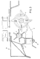
- a picking attachment 1 In the drawings, the part of a picking attachment 1 is shown in section, this picking attachment having a feed rotor 2 which is driven in rotation and is equipped with working edges 3, 4, 5 and 6. These working edges protrude beyond the circumference of the feed rotor 2, and slots 7 are arranged in the projecting parts of the working edges 3 to 6, into which comminution knives 8 protrude.
- the shredding knives 8 are carried by a frame 20, this frame also defining a picking gap 21, the width of which can be regulated by picking plates 22 and 23.
- the corn stalks, not shown in the drawing, are transported by driver fingers 24 and 25, which are carried by feed chains.
- a covering trough 18 is provided on the frame 20, which carries the comminution knives 8 at its lower end and which is pivotably supported by the frame 20 at 17 * at its other end. This makes it possible to fold out the comminution knives from the working area of the feed rotor 2.
- a counter roller 10 Associated with the feed rotor 2 is a counter roller 10, which consists of a support shaft 11 comparable to the support shaft 9 of the feed rotor 2, on which vanes 12, 14, 15, 16 and 17 are fastened.
- these wings consist of V- and / or L- and / or U-shaped components.
- the feed rotor 2 and the counter roller 10 are both driven and are connected to one another in terms of drive via a corresponding toothed drive in such a way that they always assume the same position relative to one another, the counter roller 10 rotating faster than the feed rotor 2.
- the cover trough 18 shown in Fig. 1 carries on its inside a cover plate 26, which adapts approximately to the outer envelope of the counter-roller 10, so that the corn stalks supplied by the driving fingers 24 and 25 interact after gripping by the working edges of the feed rotor 2 and with the Wings of the counter roller 10 are guided down to the comminution knives 8. Due to the rotational speed, the stem pieces shredded by the shredding knives 8 are then thrown relatively broadly, so that no swaths form below the area between the feed rotor 2 and the counter roller 10.
- the covering trough 18 is additionally equipped with a counter knife 19 which cooperates with the ends of the counter roller 10 in such a way that it is not possible to wind stems or other weeds in the region of the counter roller.
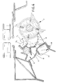
- the comminution knives 8 are no longer carried by a cover trough, but are arranged relatively directly on the frame 20, in the exemplary embodiment shown with the interposition of a carrier 27.
- This carrier 27 carries the knives with the interposition of clamping screws 28, so that after loosening the clamping screws 28, the knives are displaceable and thus adjustable.
- the wings carried by the support shaft 11 are blunt at their ends and intermittently interact with the working edges of the feed rotor 2.
- the wings are designed as L-shaped components, one leg of this L's is pointed and protrudes shorter than the circumference of the support shaft 11 than the other leg.
- the resulting enveloping circles are shown in Fig. 4 and the enveloping circle of the short, tapered leg of the wing of the mating roller 10 are marked with a3 and the enveloping circle of the longer leg of the mating roller 10 are marked with a2.
- the enveloping circle of the feed rotor 2 is also shown in Fig. 4 and bears the designation a1. From Fig.
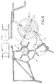
- FIGS. 1 and 2 are another type of attachment of the knife compared to FIGS. 1 and 2 selected, namely the knives are located on a cover trough 18, but are adjustable so that they are acted upon by a pressure carrier 30, the is fixed by a screw 28.
- the knife 8 can be adjusted by loosening the screw 28.
- the two cooperating work rolls, the feed rotor 2 and the counter roll 10 are set so that the tips of the wings and working edges do not face each other, but the tips of the working edges move along the inside of the pointed wing legs, whereby this movement sequence prevents the plant material from being wrapped in the area of the counter-roller and at the same time cuts and shreds the stems.
- the embodiment of the invention in which the shredding knife is dispensed with is particularly important, so that shredding of the stalks to be harvested is brought about solely by the interaction of the feed roller and the counter roller.
Landscapes
- Life Sciences & Earth Sciences (AREA)
- Environmental Sciences (AREA)
- Harvesting Machines For Specific Crops (AREA)
- Threshing Machine Elements (AREA)
- Harvesting Machines For Root Crops (AREA)
- Manipulator (AREA)
- Harvester Elements (AREA)
Claims (21)
- Appareil à cueillir (1) pour une moissonneuse pour la récolte de grains, par exemple du maïs ou analogue, comportant un rotor d'alimentation (2) prévu par rang de plantes, ce rotor étant équipé sur son pourtour d'arêtes de travail (3, 4, 5, 6) présentant des fentes (7), dans lesquelles s'engagent des lames de fragmentation (8) portées par la machine, et interagissant avec un contre-rouleau (10) équipé d'ailes (12, 13, 14, 15, 16, 17) et servant de contre-support pour le rotor d'alimentation (2), caractérisé en ce que les lames de fragmentation (8) interagissent exclusivement avec les fentes (7) du rotor d'alimentation (2).
- Appareil à cueillir selon la revendication 1, caractérisé en ce que la zone située sous le contre-rouleau (10) est fermée vers le bas.
- Appareil à cueillir selon la revendication 1 ou 2, caractérisé en ce que les lames de fragmentation (8) sont installées de façon mobile en (17).
- Appareil à cueillir selon une ou plusieurs des revendications précédentes, caractérisé en ce que les ailes (12-17) du contre-rouleau (10) sont réalisées sous forme de pièces recourbées en V et/ou en L et/ou en U.
- Appareil à cueillir selon une ou plusieurs des revendications précédentes, caractérisé en ce que les extrémités d'au moins quelques ailes (12-17) et/ou d'au moins quelques arêtes de travail (3-6) sont réalisées de façon affilée.
- Appareil à cueillir selon une ou plusieurs des revendications précédentes, caractérisé en ce que lors de leur rotation, les extrémités affilées des arêtes de travail (3-6) font face aux arêtes affilées des ailes (12-17) et écrasent et/ou entaillent et/ou découpent le brin se trouvant entre elles (figure 4).
- Appareil à cueillir selon une ou plusieurs des revendications précédentes, caractérisé par la combinaison d'ailes affilées (12-17) dont les extrémités ne touchent pas le cercle enveloppant (a₁) des bouts des arêtes de travail (3-6), avec des ailes (12-17) dont les extrémités, en rotation, s'engagent dans le cercle enveloppant (a₁) des arêtes de travail (3-6) (figure 5).
- Appareil à cueillir selon une ou plusieurs des revendications précédentes, caractérisé en ce que lors de la rotation du rotor d'alimentation (2) et du contre-rouleau (10), les bouts des arêtes de travail (3-6) glissent le long des faces intérieures des ailes (12-17) (figure 5).
- Appareil à cueillir selon une ou plusieurs des revendications précédentes, caractérisé par une cuve de protection inférieure (18) approximativement adaptée au cercle enveloppant (a₂) du contre-rouleau (10).
- Appareil à cueillir selon la revendication 9, caractérisé en ce que la cuve de protection (18) porte la lame de fragmentation (8).
- Appareil à cueillir selon la revendication 9 ou 10, caractérisé en ce que la cuve de protection (18) porte une contre-lame (19) pour les ailes (12-17) du contre-rouleau (10).
- Appareil à cueillir (1) pour une moissonneuse pour la récolte de grains, par exemple du maïs ou analogue, comportant un rotor d'alimentation (2) prévu par rang de céréales, ce rotor étant équipé sur son pourtour d'arêtes de travail (3, 4, 5, 6) et interagissant avec un contre-rouleau (10) équipé d'ailes affilées (12, 13, 14, 15, 16, 17) et servant de contre-support pour le rotor d'alimentation, caractérisé en ce que les extrémités d'au moins quelques ailes (12, 13, 14, 15, 16, 17) et d'au moins quelques arêtes de travail (3, 4, 5, 6) sont réalisées de façon affilée.
- Appareil à cueillir selon la revendication 12, caractérisé en ce que lors de leur rotation, les extrémités affilées des arêtes de travail (3-6) font face aux extrémités affilées des ailes (12-17) et écrasent et/ou entaillent et/ou découpent le brin se trouvant entre elles (figure 4).
- Appareil à cueillir selon la revendication 12 ou 13, caractérisé par la combinaison d'ailes affilées (12-17) dont les extrémités ne touchent pas le cercle enveloppant (a₁) des bouts des arêtes de travail (3-6), avec des ailes (12-17) dont les extrémités, en rotation, s'engagent dans le cercle enveloppant (a₁) des arêtes de travail (3-6) (figure 5).
- Appareil à cueillir selon au moins la revendication 12, caractérisé en ce que lors de la rotation du rotor d'alimentation (2) et du contre-rouleau (10), les bouts des arêtes de travail (3-6) glissent le long des faces intérieures des ailes (12-15) (figure 5).
- Appareil à cueillir selon une ou plusieurs des revendications précédentes 12-16, caractérisé par une cuve de protection inférieure (18) approximativement adaptée au cercle enveloppant (a₂) du contre-rouleau (10).
- Appareil à cueillir selon une ou plusieurs des revendications précédentes, caractérisé en ce que la cuve de protection(18) porte une contre-lame (19) pour les ailes (12-17) du contre-rouleau (10).
- Appareil à cueillir selon une ou plusieurs des revendications précédentes, caractérisé en ce que dans la zone avant du rotor d'alimentation (2) et/ou du contre-rouleau (10) sous la spire est disposée une lame qui sectionne les tiges des plantes relativement près du sol.
- Appareil à cueillir selon la revendication 18, caractérisé en ce que la lame est réalisée sous la forme d'un disque-couteau à dents.
- Appareil à cueillir selon la revendication 18, caractérisé en ce que la lame est réalisée sous la forme d'une lame cintrée dont le tranchant est disposé suivant la direction d'avancement.
- Appareil à cueillir selon la revendication 20, caractérisé en ce que la courbure de la lame est adaptée à la courbure de la spire du rotor d'alimentation (2) ou du contre-rouleau (10).
Applications Claiming Priority (2)
| Application Number | Priority Date | Filing Date | Title |
|---|---|---|---|
| DE4036717A DE4036717A1 (de) | 1990-11-17 | 1990-11-17 | Pflueckvorsatz fuer ein erntegeraet |
| DE4036717 | 1990-11-17 |
Publications (3)
| Publication Number | Publication Date |
|---|---|
| EP0486887A2 EP0486887A2 (fr) | 1992-05-27 |
| EP0486887A3 EP0486887A3 (en) | 1993-04-21 |
| EP0486887B1 true EP0486887B1 (fr) | 1995-03-01 |
Family
ID=6418479
Family Applications (1)
| Application Number | Title | Priority Date | Filing Date |
|---|---|---|---|
| EP91118968A Expired - Lifetime EP0486887B1 (fr) | 1990-11-17 | 1991-11-07 | Appareil à cueillir pour une moissonneuse |
Country Status (4)
| Country | Link |
|---|---|
| US (1) | US5269126A (fr) |
| EP (1) | EP0486887B1 (fr) |
| AT (1) | ATE118965T1 (fr) |
| DE (2) | DE4036717A1 (fr) |
Families Citing this family (32)
| Publication number | Priority date | Publication date | Assignee | Title |
|---|---|---|---|---|
| DE4241949C2 (de) * | 1992-12-12 | 1995-05-24 | Geringhoff Carl Gmbh Co Kg | Pflückvorsatz für ein Erntegerät |
| DE4344669C1 (de) * | 1993-12-27 | 1995-04-27 | Geringhoff Carl Gmbh Co Kg | Pflückvorsatz für ein Erntegerät |
| US6101800A (en) * | 1998-10-26 | 2000-08-15 | Juraco; Albert F. | Field chopping apparatus |
| DE19914321A1 (de) | 1999-03-30 | 2000-10-05 | Claas Saulgau Gmbh | Vorrichtung zum Pflücken von Fruchtständen |
| US9560804B1 (en) | 2010-12-15 | 2017-02-07 | Marion Calmer | Stalk roll with flutes defining a recess |
| DE102005050470B3 (de) * | 2005-10-21 | 2006-12-14 | Carl Geringhoff Gmbh & Co. Kg | Pflückvorsatz für ein Erntegerät zum Ernten von Körnerfrüchten |
| CA2678444C (fr) * | 2007-04-05 | 2012-05-29 | Iowa State University Research Foundation, Inc. | Dispositif de decoupe de materiau a double cisaillement |
| US7510472B1 (en) * | 2007-10-29 | 2009-03-31 | Cnh America Llc | Combine harvester residue chopper active counter knife assembly |
| US8864561B2 (en) * | 2009-08-26 | 2014-10-21 | Deere & Company | Harvested crop residue chopper and distribution arrangement for a combine with an impeller blower whose shape conforms to the contour of the straw chopper |
| US12279558B2 (en) | 2010-12-15 | 2025-04-22 | Calmer Holding Company, Llc | Stalk roll |
| US10785911B2 (en) | 2011-12-15 | 2020-09-29 | Marion Calmer | Stalk roll with hybrid flute having a sharp edge and two blunt edges |
| US11071252B2 (en) | 2011-12-15 | 2021-07-27 | Marion Calmer | Stalk roll with multiple flutes of different lengths |
| AR093698A1 (es) | 2012-11-30 | 2015-06-17 | Calmer Marion | Cabezal de hilera angosta |
| BR112016012603B1 (pt) * | 2013-12-06 | 2021-06-29 | S7 Ip Holdings, Llc | Plataforma de milho da colheitadeira para uma colheitadeira e combinação de unidade de fileira para uma plataforma de milho de colheitadeira |
| CN103843532B (zh) * | 2014-02-28 | 2016-02-17 | 陈永政 | 一种玉米收获机割台 |
| CN104429383A (zh) * | 2014-11-24 | 2015-03-25 | 郑宇虎 | 一种玉米秸秆对行粉碎装置 |
| US10172286B2 (en) | 2016-01-06 | 2019-01-08 | Oxbo International Corporation | Knife rolls with differing lengths |
| CN105723914A (zh) * | 2016-04-25 | 2016-07-06 | 河南田冠农业机械制造有限公司 | 静刀可调节的玉米收获机割刀总成 |
| WO2018049225A1 (fr) * | 2016-09-08 | 2018-03-15 | Marion Calmer | Rouleau pour tiges |
| CN107172966B (zh) * | 2017-05-25 | 2019-08-09 | 绍兴柯桥新兴门业有限公司 | 一种棉花杆粉碎压缩机器人 |
| DE102017124322A1 (de) * | 2017-10-18 | 2019-04-18 | Carl Geringhoff Gmbh & Co. Kg | Vorsatzgerät mit Pflückrotoren |
| CN108093897A (zh) * | 2018-01-09 | 2018-06-01 | 江苏理工学院 | 一种新型立式秸秆粉碎机 |
| CN108076869A (zh) * | 2018-01-09 | 2018-05-29 | 江苏理工学院 | 一种小型农作物秸秆粉碎机 |
| DE102018118958A1 (de) | 2018-08-03 | 2020-02-06 | Carl Geringhoff Gmbh & Co. Kg | Vorsatzgerät zur Ernte von stängeligem Halmgut |
| CN108811789A (zh) * | 2018-08-07 | 2018-11-16 | 南京申发冶金机械制造有限公司 | 打捆机、秸秆喂入切碎装置及其切割刀片 |
| US10820512B2 (en) * | 2018-08-22 | 2020-11-03 | Deere & Company | Stalk roll with blade inserts for agricultural combine |
| CN109220177A (zh) * | 2018-11-12 | 2019-01-18 | 南京申发冶金机械制造有限公司 | 玉米收获机摘穗台的秸秆切碎装置及玉米收获机 |
| USD1023700S1 (en) | 2019-02-12 | 2024-04-23 | Calmer Holding Company, Llc | Stalk roll |
| CN109769481A (zh) * | 2019-02-20 | 2019-05-21 | 农业农村部南京农业机械化研究所 | 一种秸秆分量可调的拾输装置 |
| US11369062B2 (en) * | 2019-05-15 | 2022-06-28 | Cnh Industrial America Llc | Agricultural baler with intermeshing feed rotors |
| DE102023135749A1 (de) * | 2023-12-19 | 2025-06-26 | Claas Selbstfahrende Erntemaschinen Gmbh | Pflückwalzeneinheit für ein Vorsatzgerät zum Ernten von stängeligem Erntegut |
| CN119344086A (zh) * | 2024-12-10 | 2025-01-24 | 河北宗申戈梅利农业机械制造有限公司 | 一种玉米果穗分流装置及其玉米收获机 |
Family Cites Families (10)
| Publication number | Priority date | Publication date | Assignee | Title |
|---|---|---|---|---|
| US3863431A (en) * | 1972-05-01 | 1975-02-04 | Sugar Cane Growers Coop | Apparatus for harvesting and cleaning windrowed cane |
| DE3415708A1 (de) * | 1984-04-27 | 1985-10-31 | Biso Bitter Gmbh & Co Kg, 4520 Melle | Maehdrescher |
| DE3610141A1 (de) * | 1986-03-26 | 1987-10-01 | Claas Ohg | Maiserntegeraet |
| DE3612224C2 (de) * | 1986-04-11 | 1994-11-03 | Claas Ohg | Maiserntegerät |
| DE3726967C2 (de) * | 1987-08-13 | 1995-08-03 | Claas Ohg | Erntegerät zum Ernten von Mais oder anderen Körnerfrüchten |
| DE3808324C2 (de) * | 1988-03-12 | 1996-07-11 | Claas Ohg | Erntegerät zum Ernten von Mais |
| US4845930A (en) * | 1988-05-02 | 1989-07-11 | Byron Enterprises, Inc. | Corn ear cutter machine |
| DE3828358A1 (de) * | 1988-08-20 | 1990-02-22 | Kalverkamp Klemens | Pflueckvorsatz fuer ein erntegeraet |
| DE3930777A1 (de) * | 1989-01-16 | 1990-07-19 | Claas Ohg | Erntegeraet zum ernten von mais |
| DE4028468C1 (fr) * | 1990-09-07 | 1992-05-27 | Norbert Dipl.-Ing. 6082 Moerfelden-Walldorf De Pick |
-
1990
- 1990-11-17 DE DE4036717A patent/DE4036717A1/de not_active Withdrawn
-
1991
- 1991-11-07 DE DE59104774T patent/DE59104774D1/de not_active Expired - Fee Related
- 1991-11-07 EP EP91118968A patent/EP0486887B1/fr not_active Expired - Lifetime
- 1991-11-07 AT AT91118968T patent/ATE118965T1/de not_active IP Right Cessation
-
1992
- 1992-05-05 US US07/878,765 patent/US5269126A/en not_active Expired - Fee Related
Also Published As
| Publication number | Publication date |
|---|---|
| EP0486887A2 (fr) | 1992-05-27 |
| ATE118965T1 (de) | 1995-03-15 |
| DE59104774D1 (de) | 1995-04-06 |
| EP0486887A3 (en) | 1993-04-21 |
| DE4036717A1 (de) | 1992-08-20 |
| US5269126A (en) | 1993-12-14 |
Similar Documents
| Publication | Publication Date | Title |
|---|---|---|
| EP0486887B1 (fr) | Appareil à cueillir pour une moissonneuse | |
| EP0685992B1 (fr) | Tete de coupe pour moissonneuse | |
| DE3302980C2 (fr) | ||
| EP0415419B1 (fr) | Hachoir | |
| EP0538599B1 (fr) | Hacheuse | |
| EP1671532B1 (fr) | Rotor hacheur | |
| EP0369440A1 (fr) | Procédé et appareil pour récolter les fruits sur pied | |
| DE3234657C2 (fr) | ||
| EP0124138B1 (fr) | Méthode et dispositif pour le broyage de produits végétaux | |
| EP1797753B1 (fr) | Faucheuse-hâcheuse | |
| DE4202865C2 (de) | Rasenmäher | |
| WO2014198599A1 (fr) | Moissonneuse pour moissonner des plantes a tiges | |
| EP1000533B1 (fr) | Dispositif cueilleur pour récolter des céréales | |
| EP0355441B1 (fr) | Appareil à cueillir pour une moissonneuse | |
| DE3631485A1 (de) | Strohhaecksler | |
| EP1541007B1 (fr) | Méthode et appareil pour couper et broyer en particulier des matières coupées hautes | |
| EP3228176B1 (fr) | Moissonneuse comprenant un dispositif de coupe | |
| DE3844734C2 (en) | Plucking unit for maize harvester | |
| EP0759268A1 (fr) | Procédé et dispositif pour ramasser et tasser des végétaux | |
| DE102019007585A1 (de) | Reihenunabhängiges Vorsatzgerät zum Ernten stängelförmiger Pflanzen mit einem quer zur Fahrtrichtung liegenden, durch das ganze Vorsatzgerät durchgehenden Pflückspalt | |
| EP1782680B1 (fr) | Dispositif pour le broyage de produits végétaux dans la forme de masse verte ou de jeunes buissons | |
| EP0014385A1 (fr) | Tondeuse à gazon | |
| EP3315013B1 (fr) | Moissonneuse | |
| DE29923382U1 (de) | Pflückvorsatz für ein Erntegerät | |
| DE3008094A1 (de) | Haeckselmaschine |
Legal Events
| Date | Code | Title | Description |
|---|---|---|---|
| PUAI | Public reference made under article 153(3) epc to a published international application that has entered the european phase |
Free format text: ORIGINAL CODE: 0009012 |
|
| AK | Designated contracting states |
Kind code of ref document: A2 Designated state(s): AT BE DE ES FR IT NL |
|
| PUAL | Search report despatched |
Free format text: ORIGINAL CODE: 0009013 |
|
| AK | Designated contracting states |
Kind code of ref document: A3 Designated state(s): AT BE DE ES FR IT NL |
|
| 17P | Request for examination filed |
Effective date: 19930330 |
|
| 17Q | First examination report despatched |
Effective date: 19940707 |
|
| GRAA | (expected) grant |
Free format text: ORIGINAL CODE: 0009210 |
|
| AK | Designated contracting states |
Kind code of ref document: B1 Designated state(s): AT BE DE ES FR IT NL |
|
| PG25 | Lapsed in a contracting state [announced via postgrant information from national office to epo] |
Ref country code: ES Free format text: THE PATENT HAS BEEN ANNULLED BY A DECISION OF A NATIONAL AUTHORITY Effective date: 19950301 |
|
| REF | Corresponds to: |
Ref document number: 118965 Country of ref document: AT Date of ref document: 19950315 Kind code of ref document: T |
|
| RAP4 | Party data changed (patent owner data changed or rights of a patent transferred) |
Owner name: KALVERKAMP, KLEMENS |
|
| REF | Corresponds to: |
Ref document number: 59104774 Country of ref document: DE Date of ref document: 19950406 |
|
| ET | Fr: translation filed | ||
| ITF | It: translation for a ep patent filed | ||
| PLBE | No opposition filed within time limit |
Free format text: ORIGINAL CODE: 0009261 |
|
| STAA | Information on the status of an ep patent application or granted ep patent |
Free format text: STATUS: NO OPPOSITION FILED WITHIN TIME LIMIT |
|
| 26N | No opposition filed | ||
| PGFP | Annual fee paid to national office [announced via postgrant information from national office to epo] |
Ref country code: AT Payment date: 19961129 Year of fee payment: 6 |
|
| PGFP | Annual fee paid to national office [announced via postgrant information from national office to epo] |
Ref country code: NL Payment date: 19961130 Year of fee payment: 6 |
|
| PG25 | Lapsed in a contracting state [announced via postgrant information from national office to epo] |
Ref country code: AT Free format text: LAPSE BECAUSE OF NON-PAYMENT OF DUE FEES Effective date: 19971107 |
|
| PG25 | Lapsed in a contracting state [announced via postgrant information from national office to epo] |
Ref country code: NL Free format text: LAPSE BECAUSE OF NON-PAYMENT OF DUE FEES Effective date: 19980601 |
|
| NLV4 | Nl: lapsed or anulled due to non-payment of the annual fee |
Effective date: 19980601 |
|
| PGFP | Annual fee paid to national office [announced via postgrant information from national office to epo] |
Ref country code: DE Payment date: 19990920 Year of fee payment: 9 |
|
| PGFP | Annual fee paid to national office [announced via postgrant information from national office to epo] |
Ref country code: FR Payment date: 19991029 Year of fee payment: 9 |
|
| PGFP | Annual fee paid to national office [announced via postgrant information from national office to epo] |
Ref country code: BE Payment date: 19991112 Year of fee payment: 9 |
|
| PG25 | Lapsed in a contracting state [announced via postgrant information from national office to epo] |
Ref country code: BE Free format text: LAPSE BECAUSE OF NON-PAYMENT OF DUE FEES Effective date: 20001130 |
|
| BERE | Be: lapsed |
Owner name: KALVERKAMP KLEMENS Effective date: 20001130 |
|
| PG25 | Lapsed in a contracting state [announced via postgrant information from national office to epo] |
Ref country code: FR Free format text: LAPSE BECAUSE OF NON-PAYMENT OF DUE FEES Effective date: 20010731 |
|
| PG25 | Lapsed in a contracting state [announced via postgrant information from national office to epo] |
Ref country code: DE Free format text: LAPSE BECAUSE OF NON-PAYMENT OF DUE FEES Effective date: 20010801 |
|
| REG | Reference to a national code |
Ref country code: FR Ref legal event code: ST |
|
| PG25 | Lapsed in a contracting state [announced via postgrant information from national office to epo] |
Ref country code: IT Free format text: LAPSE BECAUSE OF NON-PAYMENT OF DUE FEES;WARNING: LAPSES OF ITALIAN PATENTS WITH EFFECTIVE DATE BEFORE 2007 MAY HAVE OCCURRED AT ANY TIME BEFORE 2007. THE CORRECT EFFECTIVE DATE MAY BE DIFFERENT FROM THE ONE RECORDED. Effective date: 20051107 |