EP0486955A2 - Umfangfreiheitmessungssystem, Videomessungsfahrzeug und verbessertes Verfahren zum Ausführen von Umfangfreiheitsmessungen - Google Patents
Umfangfreiheitmessungssystem, Videomessungsfahrzeug und verbessertes Verfahren zum Ausführen von Umfangfreiheitsmessungen Download PDFInfo
- Publication number
- EP0486955A2 EP0486955A2 EP91119491A EP91119491A EP0486955A2 EP 0486955 A2 EP0486955 A2 EP 0486955A2 EP 91119491 A EP91119491 A EP 91119491A EP 91119491 A EP91119491 A EP 91119491A EP 0486955 A2 EP0486955 A2 EP 0486955A2
- Authority
- EP
- European Patent Office
- Prior art keywords
- path
- movement
- obstacles
- along
- control system
- Prior art date
- Legal status (The legal status is an assumption and is not a legal conclusion. Google has not performed a legal analysis and makes no representation as to the accuracy of the status listed.)
- Withdrawn
Links
- 238000005259 measurement Methods 0.000 title abstract description 41
- 238000000034 method Methods 0.000 title description 10
- 238000010586 diagram Methods 0.000 claims abstract description 25
- 238000013500 data storage Methods 0.000 claims description 11
- 230000005855 radiation Effects 0.000 claims description 5
- 238000004364 calculation method Methods 0.000 claims description 4
- 238000012545 processing Methods 0.000 claims description 3
- 230000000007 visual effect Effects 0.000 claims 1
- 238000001454 recorded image Methods 0.000 abstract description 3
- 238000005516 engineering process Methods 0.000 description 5
- 238000012360 testing method Methods 0.000 description 3
- 238000011161 development Methods 0.000 description 2
- 238000007689 inspection Methods 0.000 description 2
- 229920002799 BoPET Polymers 0.000 description 1
- 239000005041 Mylar™ Substances 0.000 description 1
- 239000006096 absorbing agent Substances 0.000 description 1
- 238000007664 blowing Methods 0.000 description 1
- 239000012141 concentrate Substances 0.000 description 1
- 230000007547 defect Effects 0.000 description 1
- 238000007710 freezing Methods 0.000 description 1
- 238000004519 manufacturing process Methods 0.000 description 1
- QSHDDOUJBYECFT-UHFFFAOYSA-N mercury Chemical compound [Hg] QSHDDOUJBYECFT-UHFFFAOYSA-N 0.000 description 1
- 229910052753 mercury Inorganic materials 0.000 description 1
- 239000013307 optical fiber Substances 0.000 description 1
- 238000012552 review Methods 0.000 description 1
- 230000035939 shock Effects 0.000 description 1
Images




Classifications
-
- G—PHYSICS
- G01—MEASURING; TESTING
- G01S—RADIO DIRECTION-FINDING; RADIO NAVIGATION; DETERMINING DISTANCE OR VELOCITY BY USE OF RADIO WAVES; LOCATING OR PRESENCE-DETECTING BY USE OF THE REFLECTION OR RERADIATION OF RADIO WAVES; ANALOGOUS ARRANGEMENTS USING OTHER WAVES
- G01S17/00—Systems using the reflection or reradiation of electromagnetic waves other than radio waves, e.g. lidar systems
- G01S17/88—Lidar systems specially adapted for specific applications
- G01S17/89—Lidar systems specially adapted for specific applications for mapping or imaging
-
- B—PERFORMING OPERATIONS; TRANSPORTING
- B61—RAILWAYS
- B61K—AUXILIARY EQUIPMENT SPECIALLY ADAPTED FOR RAILWAYS, NOT OTHERWISE PROVIDED FOR
- B61K9/00—Railway vehicle profile gauges; Detecting or indicating overheating of components; Apparatus on locomotives or cars to indicate bad track sections; General design of track recording vehicles
- B61K9/08—Measuring installations for surveying permanent way
-
- G—PHYSICS
- G01—MEASURING; TESTING
- G01C—MEASURING DISTANCES, LEVELS OR BEARINGS; SURVEYING; NAVIGATION; GYROSCOPIC INSTRUMENTS; PHOTOGRAMMETRY OR VIDEOGRAMMETRY
- G01C15/00—Surveying instruments or accessories not provided for in groups G01C1/00 - G01C13/00
- G01C15/002—Active optical surveying means
-
- G—PHYSICS
- G01—MEASURING; TESTING
- G01C—MEASURING DISTANCES, LEVELS OR BEARINGS; SURVEYING; NAVIGATION; GYROSCOPIC INSTRUMENTS; PHOTOGRAMMETRY OR VIDEOGRAMMETRY
- G01C7/00—Tracing profiles
- G01C7/02—Tracing profiles of land surfaces
- G01C7/04—Tracing profiles of land surfaces involving a vehicle which moves along the profile to be traced
Definitions
- the present invention relates to clearance measurement systems, a clearance measurement vehicle and a method for performing clearance measurement calculations.
- a clearance measurement system is basically designed to ensure that a particular size of railway car load can travel along its intended track section.
- the assignee of the present invention previously developed a clearance vehicle which rides along a railroad track by means of a rail guide attachment.
- the vehicle also includes a mercury bulb mounted on an "A" frame in front of the vehicle and a 35 mm camera mounted on top of the vehicle.
- a mercury bulb mounted on an "A" frame in front of the vehicle
- a 35 mm camera mounted on top of the vehicle.
- a "finger car” was used for obtaining clearances.
- the finger car was moveable along the railroad track and included a vertically extending inverted U-shaped frame with rods (fingers) extending outwardly from the frame.
- Each rod, or finger required reading to determine the amount of bend caused by touching various obstructions. This method was fairly precise, but required several workers.
- the photographic system utilizes a Chevrolet Suburban high-rail vehicle having a 35 mm camera mounted to the top of it.
- an intense light beam is emitted in a circular pattern perpendicular to the direction of movement. This light beam or plane is approximately eighteen feet measured horizontally from the camera.
- the vehicle measures clearances after dark.
- the operator stops the vehicle when the light beam illuminates structures adjacent to the track and a photograph is taken.
- the diagram scale is constant.
- the film is later developed and placed on a view graph machine so that the structure can be drawn on a piece of mylar and a clearance diagram can be produced.
- a clearance control system for measuring clearances at locations which are spaced apart along a path of movement.
- the system includes a vehicle moveable along the path of movement, radiation transmitting means supported on the vehicle for providing a beam of energy which reflects off portions of outer peripheries of obstacles and recording means for recording signals corresponding to coordinates of the obstacles.
- the recording means is supported by the vehicle in fixed relationship thereto such that the recording means can continuously record the signals while the vehicle moves along the path of movement.
- the recording means receives reflections of the beam of energy off the portions of the outer peripheries of the obstacles and the signals recorded by the recording means correspond to coordinates of the portions of the outer peripheries of the obstacles.
- the system preferably includes moveable support means for moving the recording means between first and second spaced-apart positions.
- the first position corresponds to a predetermined location at which the recording means can record the signals.
- the second position corresponds to a location at which the moveable support means can be stored while the vehicle travels from one clearance measurement site to another clearance measurement site.
- the system preferably includes means for receiving the signals from the recording means and for storing data corresponding to coordinates of the obstacles.
- the system can further include means for determining whether a reference object will pass freely along the path of movement without hitting any of the obstacles.
- the determining means can comprise a clearance diagram or computerized clearance software.
- the recording means comprises a video camera and the means for receiving the signals comprises data storage means for storing data continuously received from the video camera.
- the data corresponds to graphic coordinates of obstacles along the path of movement.
- the data also represents structural coordinates of the obstacles in relation to at least one fixed reference point at various locations along the path of movement.
- the data storage means can include a data disk on which graphic files are stored.
- the data is preferably in digitized form and data processing means comprising clearance program software can also be used to perform calculations using the data to determine whether the reference object will pass freely along the path of movement without hitting any of the obstacles.
- the inventive system preferably includes a monitor for displaying an image corresponding to the data at a selected location along the path of movement.
- a data display computer can be provided for overlaying information on the videotape.
- the path of movement comprises a railroad track and the obstacles comprise obstructions located adjacent to the railroad track.
- the vehicle can include one or more reference points within the field of view of the video camera.
- the video tapes can be stored at a single location.
- a clearance engineer uses the videotapes to determine whether a reference load can be carried by a train safely along a particular route on the railroad track. This determination can be performed using clearance diagrams or by computerized clearance software adapted to process the recorded data representing coordinates of obstacles located along the railroad track and data representing the reference load.
- the present invention provides an improved clearance measurement system for measuring clearances at locations which are spaced apart along a path of movement.
- a radiation transmitting means is used to provide a beam of energy which reflects off portions of outer peripheries of obstacles located along the path of movement.
- the reflected beam of energy is received by recording means which records signals corresponding to coordinates of the portions of the outer peripheries of the obstacles.
- the coordinates are measured in a plane which is perpendicular to the path of movement.
- the invention also provides a means for receiving the signals from the recording means and for storing data corresponding to the coordinates of the portions of the outer peripheries of the obstacles located closest to the path of movement. The data is used to determine whether a reference object will pass freely along the path of movement without hitting any of the obstacles.
- the present invention provides a clearance measurement system useful for routing shipments over railroad tracks.
- the system includes a video clearance measurement vehicle for collecting data in the form of video tapes which can later be used in performing clearance measurements.
- the clearance measurement system according to the invention is superior to any other existing clearance measurement device in terms of production and costs.
- the invention utilizes video technology and computer assisted drafting technology, thereby obviating the costly and time consuming development process required with the prior clearance measurement systems including the still photographic system.
- the video system can measure clearances approximately twice as fast as the photographic system.
- the video system can measure clearances in foul weather such as rain, snow or sub-freezing conditions.
- the video system utilizes automated equipment both for the field measurement (photography) and office analyzation.
- One aspect of the invention is to use computer assisted drafting technology in conjunction with a video picture background to actually draw structures adjacent a railroad track.
- the computer assisted drafting technology can be used to prepare a clearance diagram 1, as shown in Fig. 1.
- a clearance diagram includes information regarding obstacles located alongside and over one or more tracks over a particular distance such as several miles.
- Specialized personnel called "clearance engineers” review the clearance diagrams to determine routing of shipments of excessive height and/or width.
- a detailed description of the various notations and graphic representations in Fig. 1 are not required for a complete understanding of the present invention and are known to those skilled in the art.
- a video clearance measurement vehicle 2 in accordance with the invention is shown in Fig. 2.
- the vehicle 2 is moveable along a path of movement 3 such as a railroad track and includes a radiation transmitting means such as a light source 4 for illuminating obstacles 5 along the path of movement.
- a recording means such as a video camera 6 is supported on support means 7 located on top of the vehicle. At least one reference point 8 is provided within the field of view of the camera 6.
- the light source 4 projects a beam of light 9 which extends in a vertical plane which is perpendicular to the path of movement.
- various portions 10 of the obstacles 5 are illuminated by the beam of light 9.
- the video camera 6 continuously records the illuminated portions 10 of the obstacles 5 which are located closest to the track in the vertical and horizontal directions.
- the recorded images of the illuminated portions 10 are used to generate the clearance diagrams such as the clearance diagram shown in Fig. 1.
- a video camera views larger width than height but just the opposite is needed in measuring clearances along a railroad track.
- the desired field of view from the rail is 23 feet vertical and 10 feet laterally on each side of the railroad track.
- This problem was overcome by providing a wide angle lens and by carefully locating the video camera.
- a 5.5 mm perfect wide-angle lens is utilized which lens has to be located approximately 21 feet from the light beam 9 to achieve the desired field of view.
- suitable support means capable of supporting the camera in a stable position above and behind the roof structure of the vehicle 2.
- Another problem associated with constructing the video clearance measurement system was the provision of a suitable power supply.
- a 1200 Watt invertor, a 180 amp alternator and two large diesel batteries were installed in the vehicle 2. With this arrangement, the power supply changes 12 vDC to 120 vAC. This allows all of the video equipment and other electrical components of the video clearance measurement system to simply be plugged into an AC source.
- the vehicle 2 includes cabinets to house the various video components, the invertor and the diesel batteries.
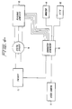
- Fig. 3 shows a layout in the vehicle 2 of various video components including a video monitor 11 and a 3/4 inch VTR 12.
- the system also includes a camera control unit and a center console control unit, both of which are not shown in Fig. 3.
- an on- board laptop computer 13 is provided so that the operator can take notes during the clearance measurements.
- a character generator 14, an encoder 15 and a digital divider 16 are also provided, as shown in Fig. 4.
- the operator can simply hit the spacebar of the personal computer 13 at each milepost and the system will change the milepost and count footage information recorded on the video tape accordingly. This feature allows the length of a structure to also be measured in order to better estimate what is required to improve clearance through such a structure.
- Fig. 5 shows how the encoder 15 cooperates with a rail guide attachment 17 which allows the vehicle 2 to be supported on the track 3.
- the encoder 15 it is possible to accurately correlate distances along the track 3 with locations of obstacles along the track 3 irrespective of the speed of the vehicle 2. That is, the video camera 6 can continue to record images continuously when the vehicle is traveling forwards and backwards and when the vehicle is stopped with the precise location of the vehicle at each point along the track being displayed directly on the videotape.
- the light source 4 concentrates light into a horizontal collimated beam 18.
- the collimated light beam 18 is reflected to form the plane of light 9 by means of a rotating prism 19.
- the prism 19 can face towards or away from the vehicle 2.
- the prism 19 faces the vehicle and the light source 4 is mounted between the vehicle 2 and the prism 19.
- the prism 19 is a right angle prism having a mirrored surface and rotating at a suitable speed such as 1200 rpm.
- the rotation creates a fixed 360° beam or plane of light 9.
- the prism 19 is mounted on the end of a rotatable shaft 20 which is rotated by a motor 21.
- a support 22 is provided for the shaft 20.
- the video tapes can be analyzed in a central office.
- the office can include a specially designed video playing machine which is used along with a computer and software designed to analyze the video tapes.
- the computer can be a 300 megabyte computer and the software can be AutoCad software.
- a clearance diagram has been developed in AutoCad from a videotape of a test structure. This clearance diagram is preferably overlayed onto an 18 inch video monitor. The structure has been surveyed to determine exactly where it is located in relation to the test track.
- the video clearance measurement vehicle 2 according to the invention preferably includes two fixed reference objects 8a, 8b within the field of view of the camera (as best shown in Fig. 7).
- the fixed objects may be structures on the vehicle and/or point light sources attached to the vehicle such as optical fiber lights.
- the fixed objects 8a, 8b are used as reference points in each videotape.
- the camera position is changeable on the vehicle 2 and the clearance diagram scale can also be changed. These positions can be adjusted to provide optimum camera stability and the desired clearance envelope.
- the clearance engineer can freeze or slowdown the video without any distortion in the picture. In this manner, the light beam can be drawn in AutoCad on the clearance diagram which will show where the particular structure locates in relation to the track.
- Clearance diagrams are stored as electronic data by track segment.
- the layers or structures are all labeled and the X and Y coordinates of each are digitized. These coordinates can be entered into a computerized clearance program.
- the AutoCad diagram including structure lines are saved as a graphic file.
- the clearance diagram for each track segment can be plotted and clearance engineers can check their shipment dimensions against the plotted structures.
- a computerized clearance program can be used to manipulate the graphic file over a particular track segment and electronically clear loaded shipments.
- a time base corrector can be utilized to slow down and freeze the video image.
- the clearance engineer can determine the position of the beam in relation to the track geometry. This allows the clearance engineer to determine whether the vehicle is in a curve, spiral or tangent track. Such information will make quite a difference in the clearance profile of the structure.
- the clearance engineer can determine exactly what needs to be done to a particular structure for improvements in available line clearance. As an example, it has been determined that in order to accommodate larger dimensions, several tunnels only require a portion of the wall to be removed instead of enlarging the entire tunnel.
- Another advantage of video playback would be for structure inspection. If desired, the structure being filmed could be illuminated by several high output exterior lights 23, as shown in Fig. 7. This will allow inspection of defects from the central office by "blowing up" portions of the videotape.
- the clearance engineer can actually draw the structures on the screen utilizing the track notes overlaid onto the videotape depicting track number, milepost location, etc.
- the video clearance measurement system has the ability to measure track center distances with AutoCad using the large volume of track videotapes available from the assignee's "Track Geometry Car". The dimensions will be up-to-date and accurate enough for calculating distances for safe passage of trains on adjacent track.
- the support means 7 is supported on a roof rack 24 and the support means 7 includes a telescopic boom including a first section 25 and an extendible second section 26.
- the camera 6 is supported on a camera mount 27 located at a free end of the second extendible section 26.
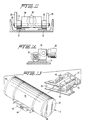
- the extendible boom can include a rack and pinion arrangement to provide smooth and stable operation, as shown in Fig. 8. Additional details of the telescopic boom are shown in Figs. 9-13.
- the support means 7 is moveable between a position A at which the camera is operated and a retracted position B at which the camera 6 is not in use.
- an actuating means is provided which can include a stationary member 28, a cam follower 29 pivoted at one end thereof to the first section 25 of the boom and pivoted at a second end thereof to a second extendible member 30 guided by the first member 28.
- the cam follower 29 is slightly inclined at an angle such as about 15 with respect to a horizontal plane.
- the roof rack 24 includes parallel tracks 31 on which rollers 32 travel.
- the rollers 32 are rotatably supported by a shaft 33 extending between spaced-apart arms forming the cam follower 29.
- the shaft 33 is also connected to the extendible member 30. Accordingly, when extendible member 30 is moved backwards and forward, the rollers 32 travel along the tracks 31 and force the cam follower 29 to pivot about the shaft 33 to raise and lower the boom between the positions A and B.
- the shaft 33 is carried by a block 34 attached to the free end of the extendible member 30.
- a heavy duty spring can be provided coaxially around the extendible member 30 such that when the extendible member 30 is retracted, the block 34 compresses the spring. The spring helps reduce the force necessary to raise the boom 7 from the fully retracted position B since it is compressed by the block 34.
- the cam follower 29 In the fully extended position, the cam follower 29 can be angled as shown in Fig. 2 or the cam follower 29 can be perpendicular to the horizontally extending roof rack 24.
- Limit switches (not shown) can be provided to deactuate a power supply used to retract and extend the extendible member 30.
- shock absorbers (not shown) extending between the section 25 and the roof rack 24 can be provided on opposite sides of the first section 25 of the boom.
- Fig. 9 shows details of the extendible boom.
- the extendible section 26 of the boom includes rollers 35 on opposite sides of the section 26. Two pairs of rollers 35 can be provided on each side of the section 26 and these pairs of rollers can be spaced apart along the length of the section 26.
- the first section 25 has an inverted U-shape and includes guide flanges 36 extending inwardly and along the length of inner sidewalls of the section 25. The rollers 35 are provided above and below the guide flanges 36 such that they smoothly guide the section 26 into and out of the section 25.
- a gear rack 37 is provided on the underside of the section 26.
- a gear 38 driven by a motor 39 engages the gear rack 37 to drive the section 26 into and out of the section 25.
- Limit switches (not shown) deactuate the motor 39 when the section reaches the fully retracted and fully extended positions.
- the section 25 is pivoted to a portion of the roof rack 24 by means of a pivot connection 40, as shown in Figs. 2 and 10.
- Fig. 13 shows details of the camera mount 27.
- the camera 6 is held within a camera housing 41 and a fitting 42 is provided on the underside of the camera housing 41 for engaging the camera mount 27.
- the camera mount 27 includes a T-shaped guide member and the fitting 42 includes a T-shaped slot 44 which engages the guide member 43.
- Hand screws 45 are provided on the camera mount 27 for clamping the fitting 42 in the camera mount 27. This arrangement permits easy removal of the camera for transportation of the vehicle.
- the camera mount 27 is provided at a preset angle at the end of the extendible section 26.
- the camera housing 41 includes a clear end plate 46 on the front thereof to protect the camera from inclement weather and prevent dirt and debris from entering the camera housing 41.
- Another end plate 47 is provided on the opposite end of the camera housing 41 and includes a cable connection 48 for connecting a cable 49 to the camera 6.
- the cable 49 supplies power to the camera and transmits the recorded image to the video components located within the vehicle 2.
- the camera mount 27 includes a vertically extending flange received in a gap between two U-shaped members forming the extendible section 26. A bolt passes through the U-shaped members and a hole in the flange extending from the camera mount 27 to allow adjustment of the angle between the camera mount 27 and the extendible member 26.
- the clearance measurements are made at night.
- the camera 6 is mounted on the camera mount 27, the motor 39 is actuated to extend the extendible section 26 of the boom and another motor (not shown) is actuated to raise the boom to the operating position A.
- the light source 4 is actuated and video images are recorded by the camera 6 while the vehicle 2 is moved along the path of movement.
- the interior of vehicle 2 is equipped with a center console next to the driver's seat.
- the monitor 11 is provided in the console to allow the driver to see the images being recorded by the camera and a camera control unit is provided to allow control of the camera iris, background, etc. if necessary.
- a microphone is also provided to allow the driver to record information directly on the video tape. Such information includes details of the obstacles or structures located along the track.
- such information includes the type of structure such as a highway overpass, switch stand, signal case, tangent track, telephone box, the direction of curve of the track, etc.
- the laptop computer 13 is also provided next to the driver to allow entry of information directly on the videotape. To indicate the milepost location along the track column the driver simply hits the spacebar on the computer 13.
- This information can be used by a clearance engineer to safely route oversized loads carried by a train from one point to another along the railroad track.
- routing could be electronically determined.
- computerized clearance program software can be developed to process the recorded data (on tape, disc, etc.) corresponding to coordinates of the obstacles along the track and process data corresponding to the reference load.
- Such a program could also take into account such factors as the weight of the load, degree of curvature of the track, proximity of the reference load to passing trains, etc.
- the video camera comprises a Sony MS 550 high resolution video camera
- the VTR comprises a Sony 3/4 inch VHS recorder
- the monitor comprises a Sony 12 inch color monitor
- the invertor comprises a Vaner 1200 Watt invertor
- the personal computer comprises a Toshiba laptop computer
- the light system comprises an Oriel 75 Watt light system.
Landscapes
- Engineering & Computer Science (AREA)
- Physics & Mathematics (AREA)
- General Physics & Mathematics (AREA)
- Radar, Positioning & Navigation (AREA)
- Remote Sensing (AREA)
- Mechanical Engineering (AREA)
- Computer Networks & Wireless Communication (AREA)
- Electromagnetism (AREA)
- Multimedia (AREA)
- Length Measuring Devices By Optical Means (AREA)
Applications Claiming Priority (2)
| Application Number | Priority Date | Filing Date | Title |
|---|---|---|---|
| US616996 | 1990-11-21 | ||
| US07/616,996 US5212655A (en) | 1990-11-21 | 1990-11-21 | Clearance measurement system, video clearance measurement vehicle and improved method of performing clearance measurements |
Publications (2)
| Publication Number | Publication Date |
|---|---|
| EP0486955A2 true EP0486955A2 (de) | 1992-05-27 |
| EP0486955A3 EP0486955A3 (en) | 1993-12-15 |
Family
ID=24471865
Family Applications (1)
| Application Number | Title | Priority Date | Filing Date |
|---|---|---|---|
| EP19910119491 Withdrawn EP0486955A3 (en) | 1990-11-21 | 1991-11-15 | Clearance measurement system, video measurement vehicle and improved method of performing clearance measurements |
Country Status (3)
| Country | Link |
|---|---|
| US (1) | US5212655A (de) |
| EP (1) | EP0486955A3 (de) |
| AU (1) | AU647997B2 (de) |
Cited By (5)
| Publication number | Priority date | Publication date | Assignee | Title |
|---|---|---|---|---|
| GB2305796A (en) * | 1995-09-26 | 1997-04-16 | London Underground Ltd | Monitoring track condition |
| CN102152802A (zh) * | 2010-12-21 | 2011-08-17 | 郑州峰华电子有限责任公司 | 铁路建筑限界测量系统及方法 |
| CN103010235A (zh) * | 2012-12-10 | 2013-04-03 | 南车成都机车车辆有限公司 | 一种隧道限界检测车 |
| CN109323674A (zh) * | 2017-07-31 | 2019-02-12 | 通用汽车环球科技运作有限责任公司 | 用于混合离地间隙确定的设备和方法 |
| CN110758455A (zh) * | 2019-09-29 | 2020-02-07 | 中国北方车辆研究所 | 一种双轨结构单驱动式柔性定位装置及闭锁装置 |
Families Citing this family (16)
| Publication number | Priority date | Publication date | Assignee | Title |
|---|---|---|---|---|
| US6064428A (en) * | 1996-08-05 | 2000-05-16 | National Railroad Passenger Corporation | Automated track inspection vehicle and method |
| US7755668B1 (en) * | 1998-04-09 | 2010-07-13 | Johnston Gregory E | Mobile surveillance system |
| US6375370B1 (en) * | 2000-02-10 | 2002-04-23 | Cam Guard Systems, Inc. | Temporary surveillance system |
| US7465108B2 (en) * | 2000-02-10 | 2008-12-16 | Cam Guard Systems, Inc. | Temporary surveillance system |
| US20080100707A1 (en) * | 2000-02-10 | 2008-05-01 | Cam Guard Systems, Inc. | Temporary surveillance system |
| US6384741B1 (en) * | 2001-01-16 | 2002-05-07 | O'leary, Sr. Jerry P. | Apparatus and method for providing high mounted view of traffic |
| GB2412261A (en) * | 2004-03-17 | 2005-09-21 | Laser Rail Ltd | Apparatus for determining the profile of structures alongside railway tracks |
| US7984863B1 (en) * | 2005-08-31 | 2011-07-26 | Alan E. Berberick | High-rise building fire fighting portable shaft system |
| US8228177B1 (en) * | 2006-03-31 | 2012-07-24 | Stanley Toshio Yamada | Automobile security device |
| US8137008B1 (en) * | 2008-04-29 | 2012-03-20 | Donato Mallano | Mobile camera mount |
| US8408347B2 (en) * | 2011-02-24 | 2013-04-02 | Chapman/Leonard Studio Equipment, Inc. | Camera car |
| ITTO20110239A1 (it) * | 2011-03-18 | 2012-09-19 | Oto Melara Spa | Struttura di posizionamento per un'arma da fuoco su un veicolo |
| US10307780B2 (en) * | 2017-06-08 | 2019-06-04 | Meyer Products, Llc | Video monitoring system for a spreader hopper |
| US11719580B1 (en) * | 2020-05-14 | 2023-08-08 | Fireside Security Group, Inc. | Integrated access gateway |
| JP7826663B2 (ja) * | 2021-11-30 | 2026-03-10 | スズキ株式会社 | 車両用センサー取付構造 |
| US12471515B2 (en) | 2023-03-23 | 2025-11-18 | Cnh Industrial America Llc | Agricultural implement with a support arm for reducing vibrations transmitted to sensors |
Family Cites Families (13)
| Publication number | Priority date | Publication date | Assignee | Title |
|---|---|---|---|---|
| US4063283A (en) * | 1975-04-03 | 1977-12-13 | Chemetron Corporation | Automatic envelope measuring system |
| US4180322A (en) * | 1978-05-01 | 1979-12-25 | Alcyon Equipment S.A. | Interior measurement of enclosed spaces |
| AU8948482A (en) * | 1981-10-27 | 1983-05-05 | B.K.S. Surveys Ltd. | Photographic tunnel sectioning light |
| JPS61281915A (ja) * | 1985-06-07 | 1986-12-12 | Kokusai Kogyo Kk | 路面性状計測車両装置 |
| JPS62155140A (ja) * | 1985-12-27 | 1987-07-10 | Aisin Warner Ltd | 車両制御用道路画像入力方式 |
| US4825393A (en) * | 1986-04-23 | 1989-04-25 | Hitachi, Ltd. | Position measuring method |
| US4809178A (en) * | 1986-05-22 | 1989-02-28 | Kabushiki Kaisha Toyota Chuo Kenkyusho | Obstacle data processing system for unmanned vehicle |
| JPH0789059B2 (ja) * | 1987-01-14 | 1995-09-27 | 株式会社日立製作所 | 視覚センサシステム |
| US4888720A (en) * | 1987-12-07 | 1989-12-19 | Fryer Glenn E | Tunnel measuring apparatus and method |
| US4970653A (en) * | 1989-04-06 | 1990-11-13 | General Motors Corporation | Vision method of detecting lane boundaries and obstacles |
| DE3913988A1 (de) * | 1989-04-27 | 1990-10-31 | Gebel Hans Peter Dr Ing | Verfahren und vorrichtung zum vermessen von strassen bezueglich achsenlaenge, breite und hoehe bzw. steigung |
| US5073819A (en) * | 1990-04-05 | 1991-12-17 | Computer Scaled Video Surveys, Inc. | Computer assisted video surveying and method thereof |
| IT1242165B (it) * | 1990-11-13 | 1994-02-16 | Comitato Naz Le Per La Ricerca | Sistema automatico per il rilevamento del profilo interno di gallerie ferroviarie e simili. |
-
1990
- 1990-11-21 US US07/616,996 patent/US5212655A/en not_active Expired - Fee Related
-
1991
- 1991-11-15 EP EP19910119491 patent/EP0486955A3/en not_active Withdrawn
- 1991-11-19 AU AU88011/91A patent/AU647997B2/en not_active Ceased
Cited By (7)
| Publication number | Priority date | Publication date | Assignee | Title |
|---|---|---|---|---|
| GB2305796A (en) * | 1995-09-26 | 1997-04-16 | London Underground Ltd | Monitoring track condition |
| CN102152802A (zh) * | 2010-12-21 | 2011-08-17 | 郑州峰华电子有限责任公司 | 铁路建筑限界测量系统及方法 |
| CN102152802B (zh) * | 2010-12-21 | 2013-03-20 | 郑州峰华电子有限责任公司 | 铁路建筑限界测量系统及方法 |
| CN103010235A (zh) * | 2012-12-10 | 2013-04-03 | 南车成都机车车辆有限公司 | 一种隧道限界检测车 |
| CN103010235B (zh) * | 2012-12-10 | 2016-05-11 | 中车成都机车车辆有限公司 | 一种隧道限界检测车 |
| CN109323674A (zh) * | 2017-07-31 | 2019-02-12 | 通用汽车环球科技运作有限责任公司 | 用于混合离地间隙确定的设备和方法 |
| CN110758455A (zh) * | 2019-09-29 | 2020-02-07 | 中国北方车辆研究所 | 一种双轨结构单驱动式柔性定位装置及闭锁装置 |
Also Published As
| Publication number | Publication date |
|---|---|
| AU8801191A (en) | 1992-05-28 |
| EP0486955A3 (en) | 1993-12-15 |
| AU647997B2 (en) | 1994-03-31 |
| US5212655A (en) | 1993-05-18 |
Similar Documents
| Publication | Publication Date | Title |
|---|---|---|
| US5212655A (en) | Clearance measurement system, video clearance measurement vehicle and improved method of performing clearance measurements | |
| CA1077158A (en) | Apparatus for measuring the profile of a railroad tunnel | |
| US7659972B2 (en) | Rail measurement system | |
| CN111366082A (zh) | 移动式接触轨检测装置及其应用方法 | |
| CN107063179B (zh) | 一种可移动式隧道断面变形检测装置 | |
| EP0953491B1 (de) | Verfahren und Vorrichtung zur Überwachung von Unregelmässigkeiten in Eisenbahn- und Strassenbahnoberbauten | |
| JPH08128015A (ja) | 橋梁点検設備およびその点検ロボット | |
| CN112710229A (zh) | 地铁接触网几何参数测量仪及测量方法 | |
| CN101580071A (zh) | 铁路机车车辆运行姿态测量系统 | |
| CN114018153B (zh) | 一种铁路工务检测分析方法、装置、设备及可读存储介质 | |
| CN211504015U (zh) | 移动式接触轨检测装置 | |
| JPH0355764B2 (de) | ||
| Wilk et al. | Innovative mobile method to determine railway track axis position in global coordinate system using position measurements performed with GNSS and fixed base of the measuring vehicle | |
| CN113761264A (zh) | 基础设施建设移动式智能巡查装备及智能管理方法 | |
| JP2700731B2 (ja) | 鉄道線路の異常検出装置 | |
| CN116183613A (zh) | 一种电缆隧道衬砌渗漏水检测装置及轮廓建模方法 | |
| JP2803963B2 (ja) | トロリ線の高さ・偏位測定方法 | |
| Auer | Multi-function track recording cars | |
| JP4238016B2 (ja) | 画像情報記録装置 | |
| CN209623637U (zh) | 一种非接触式接触轨几何形位检测装置 | |
| CN214372251U (zh) | 地铁接触网几何参数测量仪 | |
| Sasama et al. | Inspection system for railway facilities using a continuously scanned image | |
| JPH0434402Y2 (de) | ||
| JP3231386B2 (ja) | シールド測量方法 | |
| Engstrand | Railway surveying-A case study of the GRP 5000 |
Legal Events
| Date | Code | Title | Description |
|---|---|---|---|
| PUAI | Public reference made under article 153(3) epc to a published international application that has entered the european phase |
Free format text: ORIGINAL CODE: 0009012 |
|
| AK | Designated contracting states |
Kind code of ref document: A2 Designated state(s): AT BE CH DE DK ES FR GB GR IT LI LU NL SE |
|
| PUAL | Search report despatched |
Free format text: ORIGINAL CODE: 0009013 |
|
| AK | Designated contracting states |
Kind code of ref document: A3 Designated state(s): AT BE CH DE DK ES FR GB GR IT LI LU NL SE |
|
| 17P | Request for examination filed |
Effective date: 19940614 |
|
| 17Q | First examination report despatched |
Effective date: 19960318 |
|
| STAA | Information on the status of an ep patent application or granted ep patent |
Free format text: STATUS: THE APPLICATION IS DEEMED TO BE WITHDRAWN |
|
| 18D | Application deemed to be withdrawn |
Effective date: 19961001 |