EP0487073A1 - Dispositif pour l'examen de l'acuité visuelle - Google Patents
Dispositif pour l'examen de l'acuité visuelle Download PDFInfo
- Publication number
- EP0487073A1 EP0487073A1 EP91119834A EP91119834A EP0487073A1 EP 0487073 A1 EP0487073 A1 EP 0487073A1 EP 91119834 A EP91119834 A EP 91119834A EP 91119834 A EP91119834 A EP 91119834A EP 0487073 A1 EP0487073 A1 EP 0487073A1
- Authority
- EP
- European Patent Office
- Prior art keywords
- beam path
- lcd
- partial beam
- lcd shutter
- pattern
- Prior art date
- Legal status (The legal status is an assumption and is not a legal conclusion. Google has not performed a legal analysis and makes no representation as to the accuracy of the status listed.)
- Granted
Links
Images
Classifications
-
- A—HUMAN NECESSITIES
- A61—MEDICAL OR VETERINARY SCIENCE; HYGIENE
- A61B—DIAGNOSIS; SURGERY; IDENTIFICATION
- A61B3/00—Apparatus for testing the eyes; Instruments for examining the eyes
- A61B3/02—Subjective types, i.e. testing apparatus requiring the active assistance of the patient
- A61B3/028—Subjective types, i.e. testing apparatus requiring the active assistance of the patient for testing visual acuity; for determination of refraction, e.g. phoropters
- A61B3/032—Devices for presenting test symbols or characters, e.g. test chart projectors
-
- A—HUMAN NECESSITIES
- A61—MEDICAL OR VETERINARY SCIENCE; HYGIENE
- A61B—DIAGNOSIS; SURGERY; IDENTIFICATION
- A61B3/00—Apparatus for testing the eyes; Instruments for examining the eyes
- A61B3/02—Subjective types, i.e. testing apparatus requiring the active assistance of the patient
-
- A—HUMAN NECESSITIES
- A61—MEDICAL OR VETERINARY SCIENCE; HYGIENE
- A61B—DIAGNOSIS; SURGERY; IDENTIFICATION
- A61B3/00—Apparatus for testing the eyes; Instruments for examining the eyes
- A61B3/02—Subjective types, i.e. testing apparatus requiring the active assistance of the patient
- A61B3/08—Subjective types, i.e. testing apparatus requiring the active assistance of the patient for testing binocular or stereoscopic vision, e.g. strabismus
Definitions
- the invention relates to a device for examining eyesight with a binocular beam path through which the examined person views optotypes or the like.
- Examples of such devices for examining eyesight with a binocular beam path are vision test devices or so-called glasses determination devices.
- an eye test device as is known, for example, from German utility model 19 63 161 - the person examined looks over a lens and / or mirror system which generates a defined partial beam path for each eye and which also has special conditions, such as distant vision or close vision. Can create conditions on an optotype holder which presents optotypes such as optotypes, letters or numbers of different sizes, etc.
- a swiveling diaphragm is usually provided in the known eye test devices, which can either be swiveled into one or the other beam path or swiveled completely out of both beam paths.
- Such eye test devices of a different type than those provided in the preamble of claim 1 essentially consist of only one optotype holder onto which the person to be examined is directly, i.e. looks without an intermediate lens and / or mirror system.
- These eye test devices have the advantage that they are comparatively simple; it is disadvantageous, however, that there is no defined mono- or binocular beam path.
- test lenses with a certain optical effect can be introduced into each partial beam path.
- the examined person looks through the glasses determination device mono- or binocularly on an optotype holder and informs the ophthalmologist or optician of the effect with which she can best recognize optotypes of a certain size.
- the glasses determination devices currently in use have a series of lenses (Recoss lenses) arranged one behind the other in the direction of the optical axis, each of which carries a plurality of test lenses.
- the test lenses can be introduced into the beam path in such a way that a specific optical effect results in the respective partial beam path, the optical effects in the two partial beam paths being adjustable independently of one another with a fine gradation.
- diaphragms are provided on the Recoss disks that carry the test lenses, which make it possible to close the respective partial beam path in order to achieve a monocular view, whereby the Recoss disk “only has a few places to close the beam path "must be rotated.
- the invention has for its object to develop a device for examining eyesight with a binocular beam path through which the examined person views optotypes or the like in such a way that switching between binocular and monocular beam path or between the individual partial beam paths can be carried out quickly with comparatively little effort can.
- an LCD shutter is provided in each partial beam path of the binocular beam path and can be controlled by a control unit.
- the control unit controls the LCD shutters in such a way that one or both partial beam paths are opened and closed synchronously.
- LCD closures which, in contrast to the device described in DE 31 33 608 C2, are not provided in the area of the optotype holder, but in the observation beam path and in particular in the area of the optical system with the optical effect of each partial beam path, as follows is carried out in more detail - a much more flexible and varied examination procedure than LCD closures arranged in a known manner.
- they also have a number of advantages over mechanical panels or closures: Switching between translucent / opaque takes place at least then with an LCD shutter much faster than with a mechanical closure when trying to keep the effort for the mechanical closure comparatively low.
- LCD closures are much cheaper than comparable fast mechanical closures or screens.
- the design according to the invention allows "switching" from one monocular beam path to the other monocular beam path or back to a binocular beam path much faster than with mechanical shutters.
- the effort involved in controlling the closures is significantly lower.
- an otherwise conventionally constructed device can be used to check the twilight vision in addition to examining the eyesight.
- LCD shutters are not arranged in the area of the optotype holder, but in the area of the optical system of the examination device, distortions that can occur with LCD shutters play a much smaller role than with LCD shutters that are arranged directly at the viewing plane .
- the LCD closures are selectively controlled in such a way that they open or close the beam path in the form of a pattern.
- This pattern can be, for example, a centering cross or a pinhole; the LCD shutter can also perform the additional function of an intermediate screen (claim 4).
- the aforementioned properties of LCD shutters also make it possible for the control unit to control each LCD shutter in such a way that it continuously opens or closes the respective partial beam path or the pattern. In this way, for example, a switch from binocular to monocular beam path, or a switch between the partial beam paths, which is not perceptible to the examined person, can be realized.
- the training is helpful in examining the twilight eyesight (claim 6).
- the LCD closure provided according to the invention can be used in conventionally constructed eye test devices or
- Glasses determination devices can be integrated without any problems even if these devices have not yet had a mechanical lock:
- an eyeglass determination device it is possible, for example, to arrange the LCD shutter in front of or behind the test lenses instead of conventional dust protection glasses (claim 7).
- the LCD shutter can be arranged between the lens system instead of the conventional swivel screen, which creates the conditions for distant vision (claim 8).
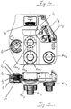
- FIG. 1 shows a part of an eyewear determination device known per se, namely the part through the viewing opening D (see FIG. 1a) of the examined person with the left eye (in FIG. 1a there is a view of the side facing the examined person) shown).
- the glasses determination device has three carrier discs (also known as Recoss discs) S1, S2, S3 and S4 for test glasses, filters etc.
- carrier disc S 1 In the closest to the eye of the person under investigation carrier disc S 1 are the adjustable with a button Kn 1 special tests.
- the carrier disk S2 carries the lenses graduated in 3 D, while the carrier disk S3 carries the glasses bridging these intervals in 0.25 D increments.
- the associated control buttons are Kn2 and Kn3.
- cylindrical lenses can be regarded as primary lenses for the carrier disc S2. They are switched on at the Kn4 button and adjusted according to the axis by the Kn5 knob.
- the glasses determination device shown in FIGS. 1a and 1b is known and is manufactured and sold by G. Rodenstock Instrumente GmbH under the name "Phoromat”.
- an LCD shutter 1 'or 1' ' is integrated into either the front or rear cover plate of the viewing opening of both beam paths, which a control unit (not shown), which is constructed in a manner known per se, controls such that one or both partial beam paths opened and closed synchronized.
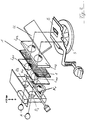
- FIG. 2 shows in perspective the binocular beam path of an eye test device.
- the two eyes of the examined person are schematically labeled A.
- the eye test device has inspection openings D 1 and D 2.
- a first lens system L l1 ..L r2 each consisting of two lenses, which creates distant vision conditions for the examined person.
- the beam path is deflected by a deflecting mirror U onto a test disk S, on which there are a number of patterns, of which only one is visible to the person examined through a diaphragm B.
- a pivotable lens system N l or N r is provided, which creates near-vision conditions.
- the eye test device is known and is also manufactured and sold by the aforementioned G. Rodenstock Instrumente GmbH.
- LCD closures 1 are provided between the two lenses L l1 and L l2 and L r1 and L r2 of the lens system which produces long-range vision conditions.
- the LCD closures which are integrated according to the invention in the devices for examining the eyesight shown in FIGS. 1 and 2, can be controlled selectively such that they open or close the partial beam path in the form of a pattern.
- the closures can also open one or both beam paths completely, so that binocular or monocular viewing of the optic signs is possible with the left or right eye.
- the pattern in which the LCD closure closes the beam path can be, for example, a centering cross.
- other patterns such as pinholes or the like are also possible.
- the LCD closures can also be controlled so that they form an intermediate panel.
- control unit can control each LCD shutter 1 or 1 'in such a way that it continuously opens or closes the respective partial beam path or the pattern, so that, for example, a "soft" transition from one mode to another is possible.
Landscapes
- Life Sciences & Earth Sciences (AREA)
- Health & Medical Sciences (AREA)
- Medical Informatics (AREA)
- Biophysics (AREA)
- Ophthalmology & Optometry (AREA)
- Engineering & Computer Science (AREA)
- Biomedical Technology (AREA)
- Heart & Thoracic Surgery (AREA)
- Physics & Mathematics (AREA)
- Molecular Biology (AREA)
- Surgery (AREA)
- Animal Behavior & Ethology (AREA)
- General Health & Medical Sciences (AREA)
- Public Health (AREA)
- Veterinary Medicine (AREA)
- Eye Examination Apparatus (AREA)
Applications Claiming Priority (2)
| Application Number | Priority Date | Filing Date | Title |
|---|---|---|---|
| DE4036964 | 1990-11-20 | ||
| DE4036964A DE4036964A1 (de) | 1990-11-20 | 1990-11-20 | Vorrichtung zur untersuchung des sehvermoegens |
Publications (2)
| Publication Number | Publication Date |
|---|---|
| EP0487073A1 true EP0487073A1 (fr) | 1992-05-27 |
| EP0487073B1 EP0487073B1 (fr) | 1997-09-03 |
Family
ID=6418623
Family Applications (1)
| Application Number | Title | Priority Date | Filing Date |
|---|---|---|---|
| EP91119834A Expired - Lifetime EP0487073B1 (fr) | 1990-11-20 | 1991-11-19 | Dispositif pour l'examen de l'acuité visuelle |
Country Status (2)
| Country | Link |
|---|---|
| EP (1) | EP0487073B1 (fr) |
| DE (2) | DE4036964A1 (fr) |
Cited By (5)
| Publication number | Priority date | Publication date | Assignee | Title |
|---|---|---|---|---|
| WO2001058340A3 (fr) * | 2000-02-09 | 2001-12-06 | Titmus Optical Inc | Appareil permettant de tester la vue |
| WO2002062209A1 (fr) * | 2001-02-07 | 2002-08-15 | Titmus Optical, Inc. | Appareil servant a tester la vue |
| WO2006118797A2 (fr) | 2005-04-29 | 2006-11-09 | Titmus Optical, Inc. | Appareil de test de la vue |
| EP2436305A1 (fr) * | 2010-09-30 | 2012-04-04 | Oculus Optikgeräte GmbH | Appareil de test visuel |
| US8764188B2 (en) | 2011-10-21 | 2014-07-01 | Kent Tabor | Functional vision tester |
Families Citing this family (1)
| Publication number | Priority date | Publication date | Assignee | Title |
|---|---|---|---|---|
| DE4222100C2 (de) * | 1992-07-07 | 1997-07-24 | Rodenstock Instr | Sehtestgerät und zugehörige Sehtestscheibe |
Citations (4)
| Publication number | Priority date | Publication date | Assignee | Title |
|---|---|---|---|---|
| US4300818A (en) * | 1978-03-13 | 1981-11-17 | Schachar Ronald A | Multifocal ophthalmic lens |
| US4726673A (en) * | 1986-05-05 | 1988-02-23 | University Of Southern California | Tachistoscope for presenting stimuli in lateralized form |
| WO1988003396A1 (fr) * | 1986-11-08 | 1988-05-19 | G. Rodenstock Instrumente Gmbh | Dispositif pour la production d'images d'un objet et notamment pour l'observation des parties arriere de l'oeil |
| WO1991000050A1 (fr) * | 1989-06-23 | 1991-01-10 | Mentor O&O, Inc. | Appareil de controle des fonctions visuelles par test de la vision binoculaire |
Family Cites Families (5)
| Publication number | Priority date | Publication date | Assignee | Title |
|---|---|---|---|---|
| DE1963163A1 (de) * | 1969-12-17 | 1971-06-24 | Walter Baetzel | Ultraschallreinigungsgeraet fuer Uhren und Schmuck |
| DE3133608C2 (de) * | 1981-01-24 | 1984-02-02 | Forschungsgesellschaft für Biomedizinische Technik, 5100 Aachen | "Anordnung zur Durchführung von Sehfunktionstests" |
| US4606624A (en) * | 1983-10-13 | 1986-08-19 | R. H. Burton Company | Refractor having simplified cylinder lens assembly |
| JPS61235310A (ja) * | 1985-04-08 | 1986-10-20 | Honda Motor Co Ltd | 塑性加工機における搬送装置 |
| US4927260A (en) * | 1988-10-11 | 1990-05-22 | Orville Gordon | Apparatus and method for the precision evaluation of visual function in the fovea centralis (macula) area of the retina |
-
1990
- 1990-11-20 DE DE4036964A patent/DE4036964A1/de not_active Withdrawn
-
1991
- 1991-11-19 EP EP91119834A patent/EP0487073B1/fr not_active Expired - Lifetime
- 1991-11-19 DE DE59108845T patent/DE59108845D1/de not_active Expired - Fee Related
Patent Citations (4)
| Publication number | Priority date | Publication date | Assignee | Title |
|---|---|---|---|---|
| US4300818A (en) * | 1978-03-13 | 1981-11-17 | Schachar Ronald A | Multifocal ophthalmic lens |
| US4726673A (en) * | 1986-05-05 | 1988-02-23 | University Of Southern California | Tachistoscope for presenting stimuli in lateralized form |
| WO1988003396A1 (fr) * | 1986-11-08 | 1988-05-19 | G. Rodenstock Instrumente Gmbh | Dispositif pour la production d'images d'un objet et notamment pour l'observation des parties arriere de l'oeil |
| WO1991000050A1 (fr) * | 1989-06-23 | 1991-01-10 | Mentor O&O, Inc. | Appareil de controle des fonctions visuelles par test de la vision binoculaire |
Cited By (10)
| Publication number | Priority date | Publication date | Assignee | Title |
|---|---|---|---|---|
| WO2001058340A3 (fr) * | 2000-02-09 | 2001-12-06 | Titmus Optical Inc | Appareil permettant de tester la vue |
| US6350032B1 (en) | 2000-02-09 | 2002-02-26 | Titmus Optical, Inc. | Vision testing apparatus |
| WO2002062209A1 (fr) * | 2001-02-07 | 2002-08-15 | Titmus Optical, Inc. | Appareil servant a tester la vue |
| WO2006118797A2 (fr) | 2005-04-29 | 2006-11-09 | Titmus Optical, Inc. | Appareil de test de la vue |
| US7390091B2 (en) | 2005-04-29 | 2008-06-24 | Sperian Protection Optical, Inc. | Vision testing apparatus |
| EP1883338A4 (fr) * | 2005-04-29 | 2013-11-20 | Sperian Prot Optical Inc | Appareil de test de la vue |
| EP2436305A1 (fr) * | 2010-09-30 | 2012-04-04 | Oculus Optikgeräte GmbH | Appareil de test visuel |
| US8579440B2 (en) | 2010-09-30 | 2013-11-12 | Oculus Optikgeraete Gmbh | Eyesight testing apparatus |
| US8764188B2 (en) | 2011-10-21 | 2014-07-01 | Kent Tabor | Functional vision tester |
| US9149185B2 (en) | 2011-10-21 | 2015-10-06 | Vision Assessment Corporation | Functional vision tester |
Also Published As
| Publication number | Publication date |
|---|---|
| EP0487073B1 (fr) | 1997-09-03 |
| DE59108845D1 (de) | 1997-10-09 |
| DE4036964A1 (de) | 1992-05-21 |
Similar Documents
| Publication | Publication Date | Title |
|---|---|---|
| DE69326038T2 (de) | Brillenartige Anzeigeapparat | |
| EP0624073B1 (fr) | Dispositif de refraction pour la determination subjective des proprietes visuelles spheriques et astigmatiques de l'oeil | |
| EP0492044B1 (fr) | Appareil destiné à l'essai de la fonction visuelle | |
| DE4114646C2 (de) | Ophthalmoskopie-Vorsatz für ein Operationsmikroskop | |
| EP0193818A1 (fr) | Stéréomicroscope pour opérations | |
| DE60214314T2 (de) | Optometrisches Instrument | |
| DE2353862A1 (de) | Verfahren und vorrichtung zur entspannung der akkommodation eines auges | |
| DE3015488A1 (de) | Vorrichtung zum ermitteln der durchtrittspunkte der beiden sichtachsen an einem brillengestell | |
| EP2831662B1 (fr) | Système de visualisation d'images tridimensionnelles | |
| EP0487073B1 (fr) | Dispositif pour l'examen de l'acuité visuelle | |
| EP0362692A2 (fr) | Lunettes pour regarder sans fatigue le plan d'images d'un écran ou autres plans d'images | |
| DE29616443U1 (de) | Sehtestgerät | |
| DE2218681A1 (de) | Ophthalmoskop | |
| DE3003588A1 (de) | Geraet zur pruefung des daemmerungssehens und der blendempfindlichkeit | |
| DE1817721A1 (de) | Flugzeugnavigationsverfahren | |
| DE19807716C2 (de) | Lochbrille, die zwei Lochblenden mit verstellbaren Löchern aufweist | |
| EP0598738B1 (fr) | Installation de refraction automatique commandee sur la base de la methode subjective | |
| DE19929958C1 (de) | Lochbrille mit oder ohne Linsen | |
| DE4313031A1 (de) | Modellauge | |
| DE3241958A1 (de) | Vorrichtung zur darbietung von sehtests, insbesondere fuer die kontrolle des weitsehens und des nahsehens einer testperson | |
| DE19723915C2 (de) | Sehvorrichtung zur Behandlung der Sehkraft | |
| DE3624835A1 (de) | Kopfgetragenes spiegelstereoskop | |
| DE7015772U (de) | Messspiegel zur zentrierung von brillenglaesern. | |
| DE720272C (de) | Verfahren und Geraet zum Pruefen der Stellung der Brillenglaeser relativ zu den Augen des Brillentraegers | |
| AT84999B (de) | Okular für Periskope, Entfernungsmesser u. dgl. Instrumente. |
Legal Events
| Date | Code | Title | Description |
|---|---|---|---|
| PUAI | Public reference made under article 153(3) epc to a published international application that has entered the european phase |
Free format text: ORIGINAL CODE: 0009012 |
|
| AK | Designated contracting states |
Kind code of ref document: A1 Designated state(s): CH DE FR GB IT LI |
|
| 17P | Request for examination filed |
Effective date: 19930119 |
|
| 17Q | First examination report despatched |
Effective date: 19941005 |
|
| GRAG | Despatch of communication of intention to grant |
Free format text: ORIGINAL CODE: EPIDOS AGRA |
|
| GRAH | Despatch of communication of intention to grant a patent |
Free format text: ORIGINAL CODE: EPIDOS IGRA |
|
| GRAH | Despatch of communication of intention to grant a patent |
Free format text: ORIGINAL CODE: EPIDOS IGRA |
|
| ITF | It: translation for a ep patent filed | ||
| GRAA | (expected) grant |
Free format text: ORIGINAL CODE: 0009210 |
|
| AK | Designated contracting states |
Kind code of ref document: B1 Designated state(s): CH DE FR GB IT LI |
|
| PG25 | Lapsed in a contracting state [announced via postgrant information from national office to epo] |
Ref country code: FR Free format text: LAPSE BECAUSE OF FAILURE TO SUBMIT A TRANSLATION OF THE DESCRIPTION OR TO PAY THE FEE WITHIN THE PRESCRIBED TIME-LIMIT Effective date: 19970903 |
|
| REG | Reference to a national code |
Ref country code: CH Ref legal event code: EP |
|
| GBT | Gb: translation of ep patent filed (gb section 77(6)(a)/1977) |
Effective date: 19970905 |
|
| REF | Corresponds to: |
Ref document number: 59108845 Country of ref document: DE Date of ref document: 19971009 |
|
| PGFP | Annual fee paid to national office [announced via postgrant information from national office to epo] |
Ref country code: DE Payment date: 19971030 Year of fee payment: 7 |
|
| PGFP | Annual fee paid to national office [announced via postgrant information from national office to epo] |
Ref country code: GB Payment date: 19971118 Year of fee payment: 7 |
|
| PG25 | Lapsed in a contracting state [announced via postgrant information from national office to epo] |
Ref country code: LI Free format text: LAPSE BECAUSE OF NON-PAYMENT OF DUE FEES Effective date: 19971130 Ref country code: CH Free format text: LAPSE BECAUSE OF NON-PAYMENT OF DUE FEES Effective date: 19971130 |
|
| EN | Fr: translation not filed | ||
| PLBE | No opposition filed within time limit |
Free format text: ORIGINAL CODE: 0009261 |
|
| STAA | Information on the status of an ep patent application or granted ep patent |
Free format text: STATUS: NO OPPOSITION FILED WITHIN TIME LIMIT |
|
| REG | Reference to a national code |
Ref country code: CH Ref legal event code: PL |
|
| 26N | No opposition filed | ||
| PG25 | Lapsed in a contracting state [announced via postgrant information from national office to epo] |
Ref country code: GB Free format text: LAPSE BECAUSE OF NON-PAYMENT OF DUE FEES Effective date: 19981119 |
|
| GBPC | Gb: european patent ceased through non-payment of renewal fee |
Effective date: 19981119 |
|
| PG25 | Lapsed in a contracting state [announced via postgrant information from national office to epo] |
Ref country code: DE Free format text: LAPSE BECAUSE OF NON-PAYMENT OF DUE FEES Effective date: 19990901 |
|
| PG25 | Lapsed in a contracting state [announced via postgrant information from national office to epo] |
Ref country code: IT Free format text: LAPSE BECAUSE OF NON-PAYMENT OF DUE FEES;WARNING: LAPSES OF ITALIAN PATENTS WITH EFFECTIVE DATE BEFORE 2007 MAY HAVE OCCURRED AT ANY TIME BEFORE 2007. THE CORRECT EFFECTIVE DATE MAY BE DIFFERENT FROM THE ONE RECORDED. Effective date: 20051119 |