EP0487224A1 - Sortiervorrichtung für Papierstoff - Google Patents
Sortiervorrichtung für Papierstoff Download PDFInfo
- Publication number
- EP0487224A1 EP0487224A1 EP91310262A EP91310262A EP0487224A1 EP 0487224 A1 EP0487224 A1 EP 0487224A1 EP 91310262 A EP91310262 A EP 91310262A EP 91310262 A EP91310262 A EP 91310262A EP 0487224 A1 EP0487224 A1 EP 0487224A1
- Authority
- EP
- European Patent Office
- Prior art keywords
- housing
- rotor assembly
- screening
- drive shaft
- chamber
- Prior art date
- Legal status (The legal status is an assumption and is not a legal conclusion. Google has not performed a legal analysis and makes no representation as to the accuracy of the status listed.)
- Granted
Links
- 238000012216 screening Methods 0.000 title claims abstract description 62
- 235000015073 liquid stocks Nutrition 0.000 abstract description 5
- 239000000463 material Substances 0.000 description 7
- 239000007788 liquid Substances 0.000 description 4
- 230000004323 axial length Effects 0.000 description 3
- 238000010276 construction Methods 0.000 description 3
- FJQXCDYVZAHXNS-UHFFFAOYSA-N methadone hydrochloride Chemical compound Cl.C=1C=CC=CC=1C(CC(C)N(C)C)(C(=O)CC)C1=CC=CC=C1 FJQXCDYVZAHXNS-UHFFFAOYSA-N 0.000 description 3
- 239000000835 fiber Substances 0.000 description 2
- 239000002245 particle Substances 0.000 description 2
- 230000002093 peripheral effect Effects 0.000 description 2
- 230000003014 reinforcing effect Effects 0.000 description 2
- 230000003466 anti-cipated effect Effects 0.000 description 1
- 238000005452 bending Methods 0.000 description 1
- 230000000903 blocking effect Effects 0.000 description 1
- 238000004140 cleaning Methods 0.000 description 1
- 230000000295 complement effect Effects 0.000 description 1
- 239000000470 constituent Substances 0.000 description 1
- 239000000356 contaminant Substances 0.000 description 1
- 230000008878 coupling Effects 0.000 description 1
- 238000010168 coupling process Methods 0.000 description 1
- 238000005859 coupling reaction Methods 0.000 description 1
- 239000012634 fragment Substances 0.000 description 1
- 230000005484 gravity Effects 0.000 description 1
- 238000012423 maintenance Methods 0.000 description 1
- NJPPVKZQTLUDBO-UHFFFAOYSA-N novaluron Chemical compound C1=C(Cl)C(OC(F)(F)C(OC(F)(F)F)F)=CC=C1NC(=O)NC(=O)C1=C(F)C=CC=C1F NJPPVKZQTLUDBO-UHFFFAOYSA-N 0.000 description 1
- 238000005192 partition Methods 0.000 description 1
- 239000002985 plastic film Substances 0.000 description 1
- 229920006255 plastic film Polymers 0.000 description 1
- 239000002984 plastic foam Substances 0.000 description 1
- 230000010349 pulsation Effects 0.000 description 1
- 239000011343 solid material Substances 0.000 description 1
- 230000000153 supplemental effect Effects 0.000 description 1
- 239000000725 suspension Substances 0.000 description 1
Images


Classifications
-
- B—PERFORMING OPERATIONS; TRANSPORTING
- B07—SEPARATING SOLIDS FROM SOLIDS; SORTING
- B07B—SEPARATING SOLIDS FROM SOLIDS BY SIEVING, SCREENING, SIFTING OR BY USING GAS CURRENTS; SEPARATING BY OTHER DRY METHODS APPLICABLE TO BULK MATERIAL, e.g. LOOSE ARTICLES FIT TO BE HANDLED LIKE BULK MATERIAL
- B07B1/00—Sieving, screening, sifting, or sorting solid materials using networks, gratings, grids, or the like
- B07B1/18—Drum screens
- B07B1/20—Stationary drums with moving interior agitators
-
- D—TEXTILES; PAPER
- D21—PAPER-MAKING; PRODUCTION OF CELLULOSE
- D21D—TREATMENT OF THE MATERIALS BEFORE PASSING TO THE PAPER-MAKING MACHINE
- D21D5/00—Purification of the pulp suspension by mechanical means; Apparatus therefor
- D21D5/02—Straining or screening the pulp
- D21D5/023—Stationary screen-drums
- D21D5/026—Stationary screen-drums with rotating cleaning foils
Definitions
- Paper mills have for many years made extensive use, for the cleaning of paper making stock, of pressure screening apparatus embodying a cylindrical perforated screening member which defines screening and accepts chambers on the opposite sides thereof in a closed housing, and wherein a rotor member operates in one of the chambers to keep the screening perforations open and free from solid material having a tendency to cling to the surface of the screening cylinder.
- the present Applicant has manufactured and sold many such screens in accordance with a series of U. S. patents, commencing with Staege No. 2,347,716, and followed by Martindale No. 2,835,173 and numerous other patents including Seifert Nos. 3,849,302 and 4,105,543.
- the stock or furnish is delivered to the screening chamber adjacent one end of the screening cylinder, and the material rejected by the screening cylinder is collected and discharged from the opposite end of the screening chamber.
- heavy reject material is prevented from entering the screening chamber so that only light reject material is removed after passing through the screening chamber, as shown in Martin-Sauzedde U. S. Patent No. 4,851,111.
- the present invention has as its primary objective the provision of apparatus of the above general character for screening paper making stock wherein the rotor assembly is specially constructed to provide it with sufficient buoyancy to counterbalance its weight when the apparatus is in operation and the housing is therefore filled with liquid stock.
- This rotor construction is advantageous in screening apparatus of otherwise conventional construction wherein the housing is upright so that the axis of the rotor is vertical, but it is especially advantageous with such screening apparatus wherein the housing and the rotor axis are horizontal.
- a screening cylinder 7 or 8 ft. in length and in diameter may weigh as much as 2000 pounds and also requires head room in excess of its length above the apparatus when it is to be removed and replaced. When the apparatus is horizontal, access to the interior thereof and the replacement of the screening cylinder are correspondingly facilitated.
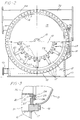
- the primary structural component of the screening apparatus shown in Figs. 1-3 is a cylindrical housing 10 which is mounted with its axis horizontal on a base 11 by brackets 12 or other suitable mounting means.
- a door 13 of domed configuration is provided with a hinged mounting 14 at the front end of the housing 10, and it also includes a centrally located outlet portion 15 for light reject material, as further described hereinafter. In its closed position, the door 13 is secured by bolts 16 to a flange 17 welded to the end of housing 10.
- a screening cylinder 20 within housing 10 is provided with perforations of any desired size and shape, e.g. round holes or slots.
- the cylinder 20 includes external reinforcing rings 21 by which it is supported at its inner end on an annular flange 22 welded to the inner surface of the housing 10, and at its middle on a ring 23 having a radially slotted outer peripheral portion 24 welded to the housing 10.
- the cylinder 20 is secured in position by a centering ring 25 secured by bolts 26 to the end ring 21 on cylinder 20 and a supplemental annular flange 27 welded to the end flange 17 on housing 10.
- the cylinder 20 separates the interior of the housing 10 into a screening chamber 30 inside the cylinder and an annular accepts chamber 31 between the cylinder and the housing which is provided with an outlet port 32, and the slotted portion 24 of ring 23 provides for free flow of liquid throughout the accepts chamber 31.
- the rotor assembly 33 which operates within screening cylinder 20 is described in detail hereinafter. It is mounted on the front end of a drive shaft 35 which extends through the open end of the housing 10 from a coupling 34 connecting it with another shaft 36 supported in a bearing housing 37 having a fixed mounting 38. The shaft 36 is in turn connected to any suitable drive 39 as indicated diagrammatically in Fig. 1.
- the inlet chamber 40 for stock to be screened is at the back or open end of the housing 10, and it is defined in part by a frustoconical wall 41 having its base welded to the back end of the housing 10 and its smaller end welded to a tubular member 42 having a reinforcing flange 43 at each end thereof.
- a tangential inlet port 44 delivers stock to be screened to the inlet chamber 40, and a tangential outlet port 45 leads from the bottom of the chamber 40 to a suitable receptacle for whatever heavy reject material may be entrained with the feed stock.
- the rotor assembly 33 which is received within the screening cylinder 20 includes a rotor body composed of an outer tubular wall 50, an inner tubular wall 51 of substantially smaller diameter than wall 50, an annular rear end wall 52, which is shown as an inwardly formed end portion of the outer wall 50, and an annular front end wall 53, all of these walls being welded together to enclose an annular sealed compartment 55. Within this compartment there may also be a partition wall 56 welded between the inner and outer walls 50 and 51 for increased stiffness.
- the rotor assembly 33 also includes a plurality of vanes 60 of airfoil shape in cross section, which are individually mounted on the outer surface of the tubular wall 50 by T-shaped brackets 61 welded to the associated vane 60 and bolted to boss members 62 welded at spaced locations on the outside of tubular member 50.
- the vanes 60 may be helically shaped as disclosed in the above Martindale patent, but satisfactory results are obtained if they are straight, and it is also desirable to utilize multiple vanes to minimize pulsing in the accepts chamber 31. Adjustment of the spacing between each vane and the inner surface of the screening cylinder 20 is readily effected by means of shims between each bracket 61 and its complementary boss 62.
- An annular hub 65 is positioned relatively centrally of the inner tubular wall 51 and is welded thereto to seal the inner end of the cylindrical space 66 which extends from hub 65 to the front end of the tubular wall 51.
- the hub 65 is internally bored with a taper to fit tightly on the complementarily tapered outer end of the drive shaft 35.
- the hub 65 is secured on the drive shaft by a plate 67 secured by bolts 68 to the end of the drive shaft 35 and the hub 65.
- the front end of the rotor assembly 33 is provided with a domed cover 70 which encloses the correspondingly dome-shaped space 71 connecting with the open space 66 in the outer end portion of the tubular wall 51 to form a second sealed compartment.
- the rim of the cover 70 is tightly secured to the remainder of the rotor assembly by bolts 72 threaded into the flange 73 on the end of the outer tubular wall 50, but which can be released to provide access to the hub 65 when the rotor assembly requires replacement.
- the drive shaft 35 is mounted in the open end of housing 10 by a drive cartridge 75 best illustrated in Fig. 4.
- the cartridge 75 include concentric outer and inner tubes 76 and 77 which are connected at their rearward ends by a ring 78, and at their forward ends by an annular bearing cap 80 having exterior spoke portions 81 to provide for drainage therebetween.
- the back end ring 78 is provided with drainage holes 82.
- the bearing cap 80 encloses bearings 83 which support the front end of the drive shaft 35, and the back end ring 78 similarly encloses supporting bearings 84 for the shaft 62.
- An annular plate 85 secured on the forward end of the outer tube 76 forms a sealed connection with a conventional seal assembly 86 secured on shaft 35.
- a slinger ring 88 is mounted on the shaft 35 just forward of the bearing cap 80 to throw to the outside any liquid which may leak past the seals 86, and such liquid can then drain between the spokes 81 on bearing cap 80 and the holes 82 in the end ring 78.
- This entire cartridge is removably mounted in the tube 42 by bolts 90 which secure a peripheral flange 91 on tube 76 to a flange 92 on the forward end of the tube 44, and by a ring 93 secured by bolts 94 to the end ring 78 and a flange 95 on the tubular wall 42.
- the rotor body be so proportioned that the annular compartment 55 and the second compartment 65/71, both of which are filled with air, provide the rotor assembly as a whole with buoyancy which will substantially counterbalance its weight when the housing 10 is filled with liquid stock.
- the rotor assembly as a whole is effectively weightless so that the drive cartridge 75 is relieved from having to support the weight of the rotor assembly which otherwise would be cantilevered therefrom.
- the feed stock enters the inlet chamber 40 tangentially through the inlet port 44 and swirls around that chamber before moving into the screening chamber 30.
- the combination of centrifugal force and gravity will therefore cause any heavy reject particles which may still be in the stock to collect along the wall of that portion of housing 10 which forms the outside of the inlet chamber, and then to exit through the reject outlet 45.
- the rotor assembly 33 will be driven to rotate in the same direction as the entering stock, i.e. clockwise as viewed in Fig.
- the vanes 60 will operate in the desired manner to create alternating positive and negative pulsations adjacent the inner ends of the perforations in the cylinder 30 to minimize the possibility of blocking of any of the perforations by the suspended fibers in the stock.
- Screening apparatus of the type of the present invention will most often be used just ahead of a paper making machine, and it is anticipated that during the preliminary preparation of that stock, at least the majority of heavy reject constituents will be eliminated. However, it is to be expected that the feed stock will still contain contaminant particles lighter than the paper making fibers, such particularly as bits of plastic film and foam too large to pass through the screening cylinder. The centrifuging action within the cylinder will cause this light reject material to be concentrated along the axis of the rotor assembly 33 in the space between the rotor cover 70 and the housing door 13, and it can be continuously bled off by maintaining a small flow of the resulting reject-rich suspension through the outlet 15 in the door.
- the housing be maintained filled with liquid stock at all times during operation of the apparatus. Therefore, the rotor assembly 33 will at all times be submerged in liquid, so that the buoyancy provided by the sealed air space comprising the annular chamber 55 and the additional chamber 66/71 can effectively counterbalance the weight of the motor assembly which would otherwise apply a downward bending moment to the drive shaft 35.
- the rotor assembly is thereby enabled to operate in accurately centered relation within the screening cylinder 20 and therefore to produce uniform action by all of the vanes 60 on its outer surface.
- Figs. 1-4 Servicing of the screening apparatus according to the invention as shown in Figs. 1-4 is greatly facilitated by the horizontal arrangement of the housing 10, to which access is readily provided by releasing the bolts 16 which hold the door 13 closed and opening this door.
- the screening cylinders in pressure screens commonly require replacement fairly often, and this operation is facilitated in screens according to the present invention by the structure and mounting of the rotor assembly 33, in that the cylinder 20 is more easily replaced if the rotor assembly is temporarily removed.
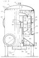
- the housing 110 is oriented vertically and is supported at its lower end by pedestal members 100, and it will be noted that while the corresponding end of the housing 100 is open, the housing 110 requires an annular bottom plate 101 and a tubular bracing member 102 extending between the inner periphery of the bottom 101 and the small end of the conical wall 141.
- the reject outlet 144 is located adjacent the bottom of the inlet chamber 140 to take maximum advantage of the gravitational forces in removing heavy reject material.
- the internal structure of the screening apparatus shown in Fig. 5 may be otherwise essentially identical with the corresponding structure already described in connection with Figs. 1-4, but the drive for the rotor assembly 133 will preferably comprise a sheave 105 on the lower end of the drive shaft 135.
- the buoyancy provided by the sealed air space in the rotor assembly will counterbalance the weight of the rotor assembly and thereby minimize the gravitational load on the bearings in the drive cartridge 175, thereby making it unnecessary to provide the heavy duty bearings and bearing housing which would otherwise normally be needed for a vertically mounted rotor assembly.
- the advantages of the invention are fully applicable to a vertically mounted screening apparatus as shown in Fig. 5.
Landscapes
- Engineering & Computer Science (AREA)
- Mechanical Engineering (AREA)
- Paper (AREA)
- Filtration Of Liquid (AREA)
Applications Claiming Priority (2)
| Application Number | Priority Date | Filing Date | Title |
|---|---|---|---|
| US615209 | 1990-11-19 | ||
| US07/615,209 US5072834A (en) | 1990-11-19 | 1990-11-19 | Screening apparatus for paper making stock |
Publications (2)
| Publication Number | Publication Date |
|---|---|
| EP0487224A1 true EP0487224A1 (de) | 1992-05-27 |
| EP0487224B1 EP0487224B1 (de) | 1996-06-05 |
Family
ID=24464456
Family Applications (1)
| Application Number | Title | Priority Date | Filing Date |
|---|---|---|---|
| EP91310262A Expired - Lifetime EP0487224B1 (de) | 1990-11-19 | 1991-11-06 | Sortiervorrichtung für Papierstoff |
Country Status (5)
| Country | Link |
|---|---|
| US (1) | US5072834A (de) |
| EP (1) | EP0487224B1 (de) |
| JP (1) | JPH04289291A (de) |
| CA (1) | CA2055025A1 (de) |
| DE (1) | DE69120031T2 (de) |
Cited By (6)
| Publication number | Priority date | Publication date | Assignee | Title |
|---|---|---|---|---|
| EP0638687A1 (de) * | 1993-08-06 | 1995-02-15 | J.M. Voith GmbH | Sortierer |
| WO1997012093A1 (de) * | 1995-09-25 | 1997-04-03 | Heinrich Fiedler Gmbh & Co. Kg | Sortiervorrichtung |
| US5960962A (en) * | 1996-02-19 | 1999-10-05 | Ahlstrom Machinery Oy | Screen |
| EP0970276A2 (de) * | 1996-02-19 | 2000-01-12 | Ahlstrom Machinery Oy | Sieb |
| US6029821A (en) * | 1995-09-25 | 2000-02-29 | Heinrich Fiedler Gmbh & Co. Kg | Screening device |
| EP1612326A1 (de) * | 2004-06-30 | 2006-01-04 | Voith Paper Patent GmbH | Drucksortierer zum Sieben einer Faserstoffsuspension |
Families Citing this family (2)
| Publication number | Priority date | Publication date | Assignee | Title |
|---|---|---|---|---|
| DE29515338U1 (de) * | 1995-09-25 | 1995-11-23 | Heinrich Fiedler GmbH & Co. KG, 93057 Regensburg | Flügel für Sortiervorrichtungen |
| EP0887459A1 (de) * | 1997-06-26 | 1998-12-30 | Voith Sulzer Papiertechnik Patent GmbH | Drucksortierer für Faserstoffsuspensionen |
Citations (4)
| Publication number | Priority date | Publication date | Assignee | Title |
|---|---|---|---|---|
| FR2377475A1 (fr) * | 1977-01-18 | 1978-08-11 | Finckh Maschf | Procede et installation de preparation et d'epuration de matiere fibreuse |
| GB2051600A (en) * | 1979-07-06 | 1981-01-21 | Lamort E & M | Paper pulp screen |
| DE3023902A1 (de) * | 1980-06-26 | 1982-01-14 | J.M. Voith Gmbh, 7920 Heidenheim | Vorrichtung zum entfernen von verunreinigungen aus einer faserstoffsuspension |
| US4328096A (en) * | 1980-03-17 | 1982-05-04 | The Black Clawson Company | Dual flow screening apparatus |
Family Cites Families (7)
| Publication number | Priority date | Publication date | Assignee | Title |
|---|---|---|---|---|
| GB1294980A (de) * | 1970-05-11 | 1972-11-01 | ||
| AT336392B (de) * | 1974-03-20 | 1977-05-10 | Finckh Metalltuch Maschf | Drucksichter fur faserstoffsuspensionen |
| DE2526657C3 (de) * | 1975-06-14 | 1978-10-26 | Hermann Finckh, Maschinenfabrik, 7417 Pfullingen | Drucksichter für Fasersuspensionen |
| DE2611886C3 (de) * | 1976-03-20 | 1981-09-03 | Hermann Finckh, Maschinenfabrik GmbH & Co, 7417 Pfullingen | Gerät zum Sortieren und Entstippen von Fasersuspensionen |
| FR2498650B2 (fr) * | 1981-01-23 | 1986-03-21 | Lamort E & M | Dispositif pour l'epuration et la recuperation de pate a papier |
| US4981583A (en) * | 1985-06-20 | 1991-01-01 | Beloit Corporation | High consistency pressure screen and method of separating accepts and rejects |
| US4855038A (en) * | 1985-06-20 | 1989-08-08 | Beloit Corporation | High consistency pressure screen and method of separating accepts and rejects |
-
1990
- 1990-11-19 US US07/615,209 patent/US5072834A/en not_active Expired - Fee Related
-
1991
- 1991-11-06 CA CA002055025A patent/CA2055025A1/en not_active Abandoned
- 1991-11-06 DE DE69120031T patent/DE69120031T2/de not_active Expired - Fee Related
- 1991-11-06 EP EP91310262A patent/EP0487224B1/de not_active Expired - Lifetime
- 1991-11-19 JP JP3303098A patent/JPH04289291A/ja active Pending
Patent Citations (4)
| Publication number | Priority date | Publication date | Assignee | Title |
|---|---|---|---|---|
| FR2377475A1 (fr) * | 1977-01-18 | 1978-08-11 | Finckh Maschf | Procede et installation de preparation et d'epuration de matiere fibreuse |
| GB2051600A (en) * | 1979-07-06 | 1981-01-21 | Lamort E & M | Paper pulp screen |
| US4328096A (en) * | 1980-03-17 | 1982-05-04 | The Black Clawson Company | Dual flow screening apparatus |
| DE3023902A1 (de) * | 1980-06-26 | 1982-01-14 | J.M. Voith Gmbh, 7920 Heidenheim | Vorrichtung zum entfernen von verunreinigungen aus einer faserstoffsuspension |
Cited By (6)
| Publication number | Priority date | Publication date | Assignee | Title |
|---|---|---|---|---|
| EP0638687A1 (de) * | 1993-08-06 | 1995-02-15 | J.M. Voith GmbH | Sortierer |
| WO1997012093A1 (de) * | 1995-09-25 | 1997-04-03 | Heinrich Fiedler Gmbh & Co. Kg | Sortiervorrichtung |
| US6029821A (en) * | 1995-09-25 | 2000-02-29 | Heinrich Fiedler Gmbh & Co. Kg | Screening device |
| US5960962A (en) * | 1996-02-19 | 1999-10-05 | Ahlstrom Machinery Oy | Screen |
| EP0970276A2 (de) * | 1996-02-19 | 2000-01-12 | Ahlstrom Machinery Oy | Sieb |
| EP1612326A1 (de) * | 2004-06-30 | 2006-01-04 | Voith Paper Patent GmbH | Drucksortierer zum Sieben einer Faserstoffsuspension |
Also Published As
| Publication number | Publication date |
|---|---|
| DE69120031D1 (de) | 1996-07-11 |
| CA2055025A1 (en) | 1992-05-20 |
| EP0487224B1 (de) | 1996-06-05 |
| US5072834A (en) | 1991-12-17 |
| JPH04289291A (ja) | 1992-10-14 |
| DE69120031T2 (de) | 1996-12-19 |
Similar Documents
| Publication | Publication Date | Title |
|---|---|---|
| US4107033A (en) | Apparatus for cleaning fibrous suspensions of low stock consistency | |
| SU776541A3 (ru) | Центрифуга дл отделени твердых частиц от жидкости | |
| US5072834A (en) | Screening apparatus for paper making stock | |
| SU1181556A3 (ru) | Устройство дл непрерывного экстрагировани жидкости из текущих суспензий | |
| NO324284B1 (no) | Apparat for fluid-bearbeiding og fremgangsmate. | |
| FI100728B (fi) | Pulssiton lajitin | |
| FI66036B (fi) | Silapparat foer massauppslamning | |
| US6955637B1 (en) | Separation device having a centrifugal rotor | |
| US4328096A (en) | Dual flow screening apparatus | |
| US5078859A (en) | Stock screening apparatus | |
| CA1163236A (en) | Dual flow screening apparatus | |
| JPH03199480A (ja) | 繊維セルローズパルプの懸濁物を濾過する装置 | |
| US5318186A (en) | Double screen basket apparatus | |
| US4851111A (en) | Apparatus for screening paper fiber stock | |
| EP0103966B1 (de) | Drehbare Filteranlage | |
| AU645778B2 (en) | Centrifugal jig pulsing system | |
| JP3067893B2 (ja) | 製紙用紙料のスクリーニング装置 | |
| US5032258A (en) | Filter centrifuge for separating suspensions with system to release accumulated gas | |
| US5078275A (en) | Screening apparatus for paper making stock | |
| US3276583A (en) | Paper machinery | |
| US2337113A (en) | Pulp screen | |
| NO139898B (no) | Anordning for rensning og fraksjonering av materialsuspensjoner | |
| US5938043A (en) | Centrifugal jig | |
| US842614A (en) | Apparatus for separating materials. | |
| US1331587A (en) | Centrifugal pulp-screen |
Legal Events
| Date | Code | Title | Description |
|---|---|---|---|
| PUAI | Public reference made under article 153(3) epc to a published international application that has entered the european phase |
Free format text: ORIGINAL CODE: 0009012 |
|
| AK | Designated contracting states |
Kind code of ref document: A1 Designated state(s): DE FR GB |
|
| 17P | Request for examination filed |
Effective date: 19921002 |
|
| 17Q | First examination report despatched |
Effective date: 19940728 |
|
| GRAH | Despatch of communication of intention to grant a patent |
Free format text: ORIGINAL CODE: EPIDOS IGRA |
|
| GRAA | (expected) grant |
Free format text: ORIGINAL CODE: 0009210 |
|
| AK | Designated contracting states |
Kind code of ref document: B1 Designated state(s): DE FR GB |
|
| RAP1 | Party data changed (applicant data changed or rights of an application transferred) |
Owner name: THE BLACK CLAWSON COMPANY |
|
| REF | Corresponds to: |
Ref document number: 69120031 Country of ref document: DE Date of ref document: 19960711 |
|
| ET | Fr: translation filed | ||
| PGFP | Annual fee paid to national office [announced via postgrant information from national office to epo] |
Ref country code: GB Payment date: 19961106 Year of fee payment: 6 |
|
| PGFP | Annual fee paid to national office [announced via postgrant information from national office to epo] |
Ref country code: FR Payment date: 19961120 Year of fee payment: 6 |
|
| PGFP | Annual fee paid to national office [announced via postgrant information from national office to epo] |
Ref country code: DE Payment date: 19961122 Year of fee payment: 6 |
|
| PLBE | No opposition filed within time limit |
Free format text: ORIGINAL CODE: 0009261 |
|
| STAA | Information on the status of an ep patent application or granted ep patent |
Free format text: STATUS: NO OPPOSITION FILED WITHIN TIME LIMIT |
|
| 26N | No opposition filed | ||
| PG25 | Lapsed in a contracting state [announced via postgrant information from national office to epo] |
Ref country code: GB Free format text: LAPSE BECAUSE OF NON-PAYMENT OF DUE FEES Effective date: 19971106 |
|
| PG25 | Lapsed in a contracting state [announced via postgrant information from national office to epo] |
Ref country code: FR Free format text: THE PATENT HAS BEEN ANNULLED BY A DECISION OF A NATIONAL AUTHORITY Effective date: 19971130 |
|
| GBPC | Gb: european patent ceased through non-payment of renewal fee |
Effective date: 19971106 |
|
| PG25 | Lapsed in a contracting state [announced via postgrant information from national office to epo] |
Ref country code: DE Free format text: LAPSE BECAUSE OF NON-PAYMENT OF DUE FEES Effective date: 19980801 |
|
| REG | Reference to a national code |
Ref country code: FR Ref legal event code: ST |