EP0487327B1 - Reiniger für Leitungswasser - Google Patents
Reiniger für Leitungswasser Download PDFInfo
- Publication number
- EP0487327B1 EP0487327B1 EP19910310702 EP91310702A EP0487327B1 EP 0487327 B1 EP0487327 B1 EP 0487327B1 EP 19910310702 EP19910310702 EP 19910310702 EP 91310702 A EP91310702 A EP 91310702A EP 0487327 B1 EP0487327 B1 EP 0487327B1
- Authority
- EP
- European Patent Office
- Prior art keywords
- valve body
- tap water
- flow path
- casing
- purifying barrel
- Prior art date
- Legal status (The legal status is an assumption and is not a legal conclusion. Google has not performed a legal analysis and makes no representation as to the accuracy of the status listed.)
- Expired - Lifetime
Links
- 239000008399 tap water Substances 0.000 title claims description 94
- 235000020679 tap water Nutrition 0.000 title claims description 94
- XLYOFNOQVPJJNP-UHFFFAOYSA-N water Chemical compound O XLYOFNOQVPJJNP-UHFFFAOYSA-N 0.000 claims description 38
- 239000008213 purified water Substances 0.000 claims description 27
- 230000002093 peripheral effect Effects 0.000 claims description 14
- 238000007789 sealing Methods 0.000 description 11
- ZAMOUSCENKQFHK-UHFFFAOYSA-N Chlorine atom Chemical compound [Cl] ZAMOUSCENKQFHK-UHFFFAOYSA-N 0.000 description 9
- 244000052616 bacterial pathogen Species 0.000 description 9
- 229910052801 chlorine Inorganic materials 0.000 description 9
- 239000000460 chlorine Substances 0.000 description 9
- 238000011109 contamination Methods 0.000 description 5
- XEEYBQQBJWHFJM-UHFFFAOYSA-N Iron Chemical compound [Fe] XEEYBQQBJWHFJM-UHFFFAOYSA-N 0.000 description 4
- 238000012856 packing Methods 0.000 description 4
- OKTJSMMVPCPJKN-UHFFFAOYSA-N Carbon Chemical compound [C] OKTJSMMVPCPJKN-UHFFFAOYSA-N 0.000 description 2
- 241000195493 Cryptophyta Species 0.000 description 2
- 229910052799 carbon Inorganic materials 0.000 description 2
- 239000000919 ceramic Substances 0.000 description 2
- 229910052742 iron Inorganic materials 0.000 description 2
- 230000001954 sterilising effect Effects 0.000 description 2
- 230000000740 bleeding effect Effects 0.000 description 1
- 230000000694 effects Effects 0.000 description 1
- JEIPFZHSYJVQDO-UHFFFAOYSA-N iron(III) oxide Inorganic materials O=[Fe]O[Fe]=O JEIPFZHSYJVQDO-UHFFFAOYSA-N 0.000 description 1
Images


Classifications
-
- B—PERFORMING OPERATIONS; TRANSPORTING
- B01—PHYSICAL OR CHEMICAL PROCESSES OR APPARATUS IN GENERAL
- B01D—SEPARATION
- B01D35/00—Filtering devices having features not specifically covered by groups B01D24/00 - B01D33/00, or for applications not specifically covered by groups B01D24/00 - B01D33/00; Auxiliary devices for filtration; Filter housing constructions
- B01D35/02—Filters adapted for location in special places, e.g. pipe-lines, pumps, stop-cocks
-
- C—CHEMISTRY; METALLURGY
- C02—TREATMENT OF WATER, WASTE WATER, SEWAGE, OR SLUDGE
- C02F—TREATMENT OF WATER, WASTE WATER, SEWAGE, OR SLUDGE
- C02F1/00—Treatment of water, waste water, or sewage
- C02F1/001—Processes for the treatment of water whereby the filtration technique is of importance
- C02F1/003—Processes for the treatment of water whereby the filtration technique is of importance using household-type filters for producing potable water, e.g. pitchers, bottles, faucet mounted devices
-
- B—PERFORMING OPERATIONS; TRANSPORTING
- B01—PHYSICAL OR CHEMICAL PROCESSES OR APPARATUS IN GENERAL
- B01D—SEPARATION
- B01D35/00—Filtering devices having features not specifically covered by groups B01D24/00 - B01D33/00, or for applications not specifically covered by groups B01D24/00 - B01D33/00; Auxiliary devices for filtration; Filter housing constructions
- B01D35/02—Filters adapted for location in special places, e.g. pipe-lines, pumps, stop-cocks
- B01D35/04—Plug, tap, or cock filters filtering elements mounted in or on a faucet
- B01D35/043—Reversible faucet filters
-
- C—CHEMISTRY; METALLURGY
- C02—TREATMENT OF WATER, WASTE WATER, SEWAGE, OR SLUDGE
- C02F—TREATMENT OF WATER, WASTE WATER, SEWAGE, OR SLUDGE
- C02F2307/00—Location of water treatment or water treatment device
- C02F2307/06—Mounted on or being part of a faucet, shower handle or showerhead
-
- Y—GENERAL TAGGING OF NEW TECHNOLOGICAL DEVELOPMENTS; GENERAL TAGGING OF CROSS-SECTIONAL TECHNOLOGIES SPANNING OVER SEVERAL SECTIONS OF THE IPC; TECHNICAL SUBJECTS COVERED BY FORMER USPC CROSS-REFERENCE ART COLLECTIONS [XRACs] AND DIGESTS
- Y10—TECHNICAL SUBJECTS COVERED BY FORMER USPC
- Y10T—TECHNICAL SUBJECTS COVERED BY FORMER US CLASSIFICATION
- Y10T137/00—Fluid handling
- Y10T137/8593—Systems
- Y10T137/85946—Faucet connected, sink drained
Definitions
- the invention relates to a tap water purifier to be directly coupled to a faucet pipe for purifying tap water from the faucet pipe.
- a tap water purifier to be directly coupled to a faucet pipe has been commonly used, which comprises a water purifying barrel filled with a filter medium such as active carbon, ceramics or hollow yarn.
- the purifying barrel is received in a receptacle which is fixedly connected to a changeover cock.
- the changeover cock is attached to the opening end of a faucet pipe so that the tap water flows from the faucet pipe into the purifying barrel in the receptacle through the changeover cock.
- the tap water is purified by the filter medium in the purifying barrel and then discharged from the lower end of the receptacle.
- the changeover cock includes a lever which can be turned through a given angle to switch the flow path in the changeover cock so that the tap water is discharged from the lower end of the changeover cock without passing through the receptacle and the purifying barrel.
- the purifying barrel is cartridge type which can be removed from the receptacle for exchange for a fresh one when the water purifier has been used for a long time and the purifying effect thereof is lowered.
- the tap water purifier has a problem that the purifying barrel is subject to internal contamination with the dirt, iron rust or algae contained in the tap water as it is used.
- the contamination causes a hotbed of germs.
- the contamination also results in the clogging of the filter medium. Therefore, it is desirable to periodically clean the purifying barrel in the receptacle to eliminate the contamination before it is exchanged for a fresh one.
- the tap water purifier has another problem that water channels are formed in the filter medium as it is used so that the tap water flows through the water channels without being purified effectively.
- GB-A-2156489 discloses a tap water purifier to be directly coupled to a faucet pipe comprising: a purifying barrel filled with a filter medium and having opposite opening ends; a casing including a cylindrical bore formed therein and having tap water inlet port means, tap water outlet port means and purified water outlet port means formed therein, said tap water inlet port means opening to said cylindrical bore of the casing; and a valve body inserted in said cylindrical bore of the casing.
- the present invention provides a simpler arrangement of port means, valve body and purifying barrel according to the characterising portion of claim 1 which solves the above-mentioned problems.
- a tap water purifier is illustrated, which is directly coupled to a faucet pipe 2 to purify tap water from the faucet pipe 2.
- the tap water purifier comprises a water purifying barrel 4 which is filled with a filter medium, such as active carbon, ceramics or hollow yarn, and inserted and received in a receptacle 6, as shown in Fig. 2.
- the purifying barrel 4 is cartridge tipe which can be removed from the receptacle 6 for exchange for a fresh one.
- the receptacle 6 includes a cover 7 which can be removed when exchanging the purifying barrel 4.
- the tap water purifier also includes a cylindrical valve body 8 which is integral with the purifying barrel 4.
- the receptacle 6 includes a cylindrical portion 10 projecting therefrom.
- the valve body 8 includes a central bore formed therein, the cylindrical portion 10 being inserted and received in the central bore.
- a fastening screw 12 is passed through a hole formed in the valve body 8 and fitted in and threadedly engaged with a hole formed in the cylindrical portion 10 whereby the receptacle 6 is fixedly attached to the valve body 8 and the valve body 8 and the purifying barrel 4 are integrated with each other.
- the tap water purifier further comprises a casing 14 including a cylindrical bore 16 formed therein for the valve body 8.
- the valve body 8 is inserted in the cylindrical bore 16 in the casing 14 for rotation about the longitudinal axis of the valve body 8, the receptacle 6 being disposed outwardly of the casing 14.
- a cap nut 18 is threadedly engaged with the outer thread of the casing 14 and abutted against the end surface of the valve body 8 to hold the valve body 8 in the cylindrical bore 16. Accordingly, the receptacle 6 can be operated to turn it integrally with the purifying barrel 4 and the valve body 8 about the longitudinal axis of the valve body 8.
- the casing 14 has a tap water inlet port 20, a pair of tap water outlet ports 22 and a purified water outlet port 24 formed therein.
- the tap water inlet port 20 and the tap water outlet port 24 extend in diametrical opposite directions to each other to open to the cylindrical bore 16 of the casing 14 at an angular distance of 180 ° from each other in the same axial position.
- the tap water outlet ports 24 extend radially of the casing 14 to open to the cylindrical bore 16 of the casing 14 in positions axially spaced from the purified water outlet port 24 on the opposite sides thereof.
- the casing 14 is attached to the opening end of the faucet pipe 2 by a cap nut 26 and a split ring 28 so that the fauce pipe 2 is communicated with the tap water inlet port 20 of the casing 14.
- the cap nut 26 is threadedly engaged with the outer thread of the casing 14, the split ring 28 being interposed between the cap nut 26 and the faucet pipe 2.
- a rubber packing 30 is interposed between the faucet pipe 2 and the casing 14 around the inlet port 20 for sealing.
- the valve body 8 extends horiontally below the opening end of the faucet pipe 2, the tap water inlet port 20 extending between the opening end of the faucet pipe 2 and the valve body 8, the tap water outlet ports 22 and the purified water outlet port 24 extending downwardly of the valve body 8.
- a shower head 32 comprising a cap nut is threadedly engaged with the outer thread of the casing 14.
- the shower head 32 includes a number of small holes 34 and a central hole 36 formed therein, the small holes 34 being communicated with the tap water outlet ports 22, the central hole 36 being communicated with the purified water outlet port 24.
- the valve body 8 includes first and second flow paths 38 and 40, the first flow path 38 comprising an axial hole 42 and a radial hole 44 formed in the valve body 8, the second flow path 40 comprising an axial hole 46 and a radial hole 48 formed in the valve body 8.
- the purifying barrel 4 has opposite opening ends 50 and 52, the axial hole 42 of the first flow path 38 being communicated with one opening end 50 of the purifying barrel 4 by means of a axial hole 54 formed in the cylindrical portion 10 and a flow channel 56 formed between the cover 7 and the purifying barrel 4.
- the axial hole 46 of the second flow path 40 is communicated with the other opening end 52 of the purifying barrel 4 by means of a axial hole 58 formed in the cylindrical portion 10 and a flow channel 60 formed between the receptacle 6 and the purifying barrel 4.
- the radial holes 44 and 48 of the first and second flow paths 38 and 40 extend in diametrical opposite directions to each other to open to the peripheral surface of the valve body 8 at an angular distance of 180° from each other in an axial position corresponding to the opening positions of the tap water inlet port 20 and the purified outlet port 24.
- the valve body 8 also includes a third flow path 62 which comprises an axial groove 64 formed in the peripheral surface of the valve body 8 in an angular position between the opening positions of the first and second flow paths 38 and 40, as shown in Fig. 3.
- the axial groove 64 extends axially of the valve body 8 to open to the peripheral surface of the valve body 8 in the angular position between the opening positions of the first and second flow paths 38 and 40 and in the axial position corresponding to the opening position of the tap water inlet port 20.
- the radial hole 44 and the axial groove 64 of the first and third flow paths 38 and 62 are positioned at an angular distance of 90° from each other, the radial hole 48 and the axial groove 64 of the second and third flow paths 40 and 62 being also positioned at an angular distance of 90 ° from each other.
- the third flow path 62 further comprises a pair of annular grooves 66 formed in the peripheral surface of the valve body 8 in positions axially spaced from the first and second flow paths 38 and 40 on the opposite sides thereof.
- the annular grooves 66 extend peripherally of the valve body 8 to be communicated with the axial groove 64 and the tap water outlet ports 22 of the casing 14.
- the valve body 8 includes a pair of sealing rings 68 extending around the opening positions of the first and second flow paths 38 and 40 and sealingly engaged with inner surface of the casing 14.
- the valve body 8 also includes a sealing ring 70 extending peripherally of the valve body 8 and sealingly engaged with inner surface of the casing 14.
- Sealing rings 72 are interposed between and sealingly engaged with the cylindrical portion 10 of the receptacle 6 and the valve body 8 on the outside and inside of the first and second flow paths 38 and 40.
- the receptacle 6 includes sealing rings 74 extending along the inner surface of the receptacle 6 and sealingly engaged with the purifying barrel 4 and the cover 7.
- a ball 76 and a spring 78 are installed between the valve body 8 and the casing 14.
- a plurality of recesses 80 are formed in the bottom of the casing 14.
- the recesses 80 are positioned at angular intervals in a circle extending about the longitudinal axis of the valve body 8.
- the ball 76 is resiliently urged by the spring 78 to fit in one of the recesses 80 every time the valve body 8 is turned through 90 ° so as to ascertain the angle of rotation of the valve body 8.
- the receptacle 6 can be operated to turn it integrally with the valve body 8 and the purifying barrel 4.
- the valve body 8 is turned to the angular position shown in Fig. 2.
- the first flow path 38 is therefore aligned and communicated with the tap water inlet port 20 of the casing 14.
- the second flow path 40 is simultaneously aligned and communicated with the purified water outlet port 24 of the casing 14.
- the tap water flows from the faucet pipe 2 to the flow channel 56 in the receptacle 6 through the tap water inlet port 20 and the first flow path 38 to enter the one opening end 50 of the purifying barrel 4.
- the tap water then passes through the purifying barrel 4 to be purified by the filter medium therein and discharged from the other opening end 52 of the purifying barrel 4.
- the purified water is directed to the purified water outlet port 24 through the flow channel 60 and the second flow path 40 and discharged from the central hole 36 of the shower head 32.
- the valve body 8 When the receptacle 6 and the purifying barrel 4 are turned through 90° from the vertical position shown in Fig. 1 to a horizontal position as shown in Fig. 4 and the ball 76 fits in another recess 80, the valve body 8 is also turned through 90° from the angular position shown in Fig. 2.
- the third flow path 62 is therefore aligned and communicated with the tap water inlet port 20 of the casing 14.
- the tap water flows from the faucet pipe 2 to the tap water outlet ports 22 through the tap water inlet port 20 and the third flow path 62 so that the tap water is discharged from the small holes 34 in the shower head 32 without passing through the receptacle 6 and the purifying barrel 4.
- the second flow path 40 is aligned and communicated with the tap water inlet port 20, contrary to the angular position shown in Fig. 2.
- the first flow path 38 is simultaneously aligned and communicated with the purified water outlet port 24. Accordingly, the tap water flows from the faucet pipe 2 to the flow channel 60 in the receptacle 6 through the tap water inlet port 20 and the second flow path 40 to enter the other opening end 52 of the purifying barrel 4 so that the tap water is forced to reversely flow through the purifying barrel 4.
- the tap water is then discharged from the one opening end 50 of the purifying barrel 4, directed to the purified water outlet port 24 through the flow channel 56 and the first flow path 38 and discharged from the central hole 36 of the shower head 32.
- the purifying barrel 4 can be cleaned by the reversely flowing water.
- it is merely required to simply turn the receptacle 6. Accordingly, it is easy to periodically clean the purifying barrel 4 so that the purifying barrel 4 is not subject to internal contamination with the dirt, iron or algae contained in the tap water. The germs will therefore not breed in the water purifying barrel 4.
- the filter medium in the purifying barrel 4 will be not clogged.
- water channels formed in the filter medium are broken by the reversely flowing water. Accordingly, the tap water can effectively purified by passing through the filter medium.
- the purified water is contained in the flow channel 60 in the receptacle 6 and the second flow path 40 in the valve body 8, the purified water including no chlorine.
- the tap water which is discharged from the faucet pipe 2 and not yet purified.
- the tap water includes chlorine therein, the chlorine having a sterilizing effect. Accordingly, when the tap water purifier is left unused for a long time, it is preferable that the receptacle 6 is turned through 180° from the vertical position shown in Fig.
- the second flow path 40 and the flow channnel 60 in which the purified water is contained the second flow path 40 is communicated with the tap water inlet port 20 which is connected to the facet pipe 2. Accordingly, the germs are shut out by the tap water in the faucet pipe 2, the germs never entering the second flow path 40. The germs therefore never enter and breed in the purifying barrel 4.
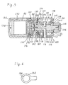
- FIG. 5 another embodiment of the invention is illustrated, which includes a water purifying barrel 82 received in a receptacle 84 for rotation about the longitudinal axis of a valve body 86.
- the purifying barrel 82 is attached to the valve body 86 for removal therefrom by means of a member 88 which is fixed to the valve body 86 by a fastening screw 90, the purifying barrel 82 being threadedly engaged with the outer thread of the member 88 so that the valve body 86 and the purifying barrel 82 are integrated with each other.
- a sealing ring 92 is interposed between and sealingly engaged with the purifying barrel 82 and the member 88.
- a sealing ring 94 is interposed between and sealingly engaged with the member 88 and valve body 86.
- a casing 96 includes a cylindrical bore 98 formed therein, the valve body 86 being inserted in the cylindrical bore 98 in the casing 96 for rotation about the longitudinal axis of the valve body 86.
- the receptacle 84 is disposed outwardly of the casing 96 and attached to the casing 96 for removal therefrom, the receptacle 84 being threadedly engaged with the outer thread of the casing 96.
- a sealing ring 100 is interposed between and sealingly engaged with the receptacle 84 and the casing 96.
- a lever 102 is disposed outwardly of the casing 96 and attached to the valve body 86 on the opposite side to the purifying barrel 82 and the receptacle 84.
- the lever 102 is fixed to the valve body 86 by a fastening screw 104 which is covered by a cap 106.
- the cap 106 is fitted in a recess formed in the lever 102.
- the lever 102 includes a handle as shown in Fig. 6.
- a cap nut 108 is used to attach the casing 96 to the opening end of a faucet pipe in a manner as described concerning the embodiment shown in Fig. 2.
- the casing 96 has a tap water inlet port 110, a pair of tap water outlet ports 112 and a purified water outlet port 114 formed therein and opening to the cylindrical bore 98 in the casing 96 in the same manner as said embodiment.
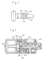
- the valve body 86 includes first, second and third flow paths 116, 118 and 120 opening to the peripheral surface of the valve body 86 in the same manner as said embodiment, as shown in Fig. 7.
- the valve body 86 is provided with a pair of sealing rings 122 extending around the opening positions of the first and second flow paths 116 and 118 and sealingly engaged with the inner surface of the casing 96.
- the valve body 86 further includes sealing rings 124 and 126 extending peripherally of the valve body 86 and sealingly engaged with the inner surface of the casing 96.
- the first flow path 116 is communicated with one opening end 128 of the purifying barrel 82 by means of an axial and radial hole 130 formed in the member 88 and a flow channel 132 formed between the receptacle 84 and the purifying barrel 82.
- the second flow path 118 is communicated with the other opening end 134 of the purifying barrel 82 by means of an axial hole 136 formed in the member 88.
- the casing 96 is provided with a ball 138 and a spring 140.
- a plurality of recesses 142 are formed in the peripheral surface of the valve body 86 at angular intervals in a circle extending along the peripheral surface of the valve body 86.
- the ball 138 is resiliently urged by the spring 140 to fit in one of the recesses 142 every time the valve body 86 is turned through 90 °, the spring 140 being engaged with and supported by the flange 144 of a sleeve 146 which is adhesively fixed to the casing 96.
- a shower head 148 includes a number of small holes 150 and a central hole, the shower head being threadedly engaged at the central hole with the outer thread of the sleeve 146.
- a sealing ring 152 is interposed between and sealingly engaged with the shower head 148 and the casing 96.
- the small holes 150 are communicated with the tap water outlet ports 112.
- the lever 102 can be operated to turn it integrally with the valve body 86 and the purifying barrel 82.
- the valve body 86 and the purifying barrel 82 are turned to the angular position shown in Figs. 5 and 6 and the ball 138 fits in one of the recesses 142, the first flow path 116 is aligned and communicated with the tap water inlet port 110 of the casing 96.
- the second flow path 118 is aligned and communicated with the purified water outlet port 114 of the casing 96.
- the tap water flows from the faucet pipe to the flow channel 132 in the receptacle 84 through the tap water inlet port 110 and the first flow path 116 to enter the one opening end 128 of the purifying barrel 82.
- the tap water then passes through the purifying barrel 82 to be purified by the filter medium therein and discharged from the other opening end 134 of the purifying barrel 82.
- the purified water is directed to the purified water outlet port 114 through the second flow path 118 and dischaged from the shower head 148.
- the third flow path 120 is aligned and communicated with the tap water inlet port 110. Accordingly, the tap water flows from the faucet pipe to the tap water outlet ports 112 through the tap water inlet port 110 and the third flow path 120 so that the tap water is discharged from the small holes 150 in the shower head 148 without passing through the receptacle 84 and the purifying barrel 82.
- the second flow path 118 is aligned with the tap water inlet port 110 of the casing 96, the first flow path 116 being aligned with the purified water outlet port 114 of the casing 96.
- the tap water is forced to reversely flow through the purifying barrel 82 so that the purifying barrel 82 can be cleaned by the reversely flowing water.
- the clogging of the filter medium can be broken by the reversely flowing water.
- the water channels formed in the filter medium can be also broken by the reversely flowing water. It is also possible to prevent the germs from entering and bleeding in the purifying barrel 82 when the tap water purifier is left unused for a long time, in the same manner as the embodiment shown in Fig. 2.
- Fig. 8 shows the other embodiment of the invention in which a purifying barrel 154 is disposed outwardly of the casing 158 and threadedly engaged with the inner thread formed in the valve body 160 to be attached thereto. Accordingly, the purifying barrel 154 can be removed from the valve body 160 for exchange for a fresh one.
- a rubber packing 162 is sandwiched between and sealingly engaged with the purifying barrel 154 and the valve body 160.
- the valve body 160 includes first and second flow paths 164 and 166, the first flow path 164 being communicated with one opening end 168 of the purifying barrel 154 by means of a through hole 170 formed in the rubber packing 162, the second flow path 166 being communicated with the other opening end 172 of the purifying barrel 154 by means of a through hole 174 formed in the rubber packing 162.
- Other parts and portions in this embodiment are substantially identical with the embodiment shown in Fig. 5.
Landscapes
- Chemical & Material Sciences (AREA)
- Engineering & Computer Science (AREA)
- Water Supply & Treatment (AREA)
- Chemical Kinetics & Catalysis (AREA)
- Life Sciences & Earth Sciences (AREA)
- Hydrology & Water Resources (AREA)
- Environmental & Geological Engineering (AREA)
- Organic Chemistry (AREA)
- Water Treatment By Sorption (AREA)
- Separation Using Semi-Permeable Membranes (AREA)
- Multiple-Way Valves (AREA)
- Taps Or Cocks (AREA)
Claims (6)
- Leitungswasserreiniger zur direkten Verbindung mit einem Wasserhahnrohr (2), mit- einem Reinigungsfaß (4, 82, 154), das mit einem Filtermedium gefüllt ist und gegenüberliegende Öffnungsenden (50, 52, 128, 134, 180, 172) hat,- einem Gehäuse (14, 96, 158), das eine darin ausgebildete zylindrische Bohrung (16, 98) umfaßt und eine Leitungswassereinlaßöffnungseinrichtung (20, 110), eine Leitungswasserauslaßöffnungseinrichtung (22, 112) und eine Auslaßöffnungseinrichtung (24, 114) für gereinigtes Wasser hat, die darin ausgebildet sind, wobei die Wassereinlaßöffnungseinrichtung (20, 110) in die zylindrische Bohrung (16, 98) des Gehäuses (14, 96, 158) mündet,- einem Ventilkörper (8, 86, 160), der in die zylindrische Bohrung (16, 98) des Gehäuses (14, 96, 158) eingesetzt ist,dadurch gekennzeichnet, daß die Auslaßöffnungseinrichtung (24, 114) außerdem in die zylindrische Bohrung (16, 98) des Gehäuses (14, 96, 158) unter einem Winkelabstand von 180° zur Leitungswassereinlaßöffnungseinrichtung (20, 110) in derselben axialen Position mündet, wobei der zylindrische Ventilkörper (8, 86, 160) mit dem Reinigungsfaß (4, 82, 154) für eine Drehung relativ zum Gehäuse um die Längsachse des Ventilkörpers (8, 86, 160) integral ausgebildet ist,
daß eine erste Strömungswegeinrichtung (38, 116, 164) in dem Ventilkörper (8, 86, 160) ausgebildet ist und mit einem Öffnungsende (50, 128, 168) des Reinigungsfasses (4, 82, 154) in Verbindung steht,
daß eine zweite Strömungswegeinrichtung (40, 118, 166) in dem Ventilkörper (8, 86, 160) ausgebildet ist und mit dem anderen Öffnungsende (52, 134, 172) des Reinigungsfasses (4, 82, 154) in Verbindung steht, wobei die ersten und zweiten Strömungswegeinrichtungen (38, 40, 116, 188, 164, 166) in die Umfangsfläche des Ventilkörpers (8, 86, 160) unter einem Winkelabstand von 180° voneinander in einer axialen Position münden, die den Mündungspositionen der Leitungswassereinlaßöffnungseinrichtung (20, 110) der Auslaßeinrichtung (24, 114) für gereinigtes Wasser so entspricht, daß die erste Strömungswegeinrichtung in einer Position des Ventilkörpers in Verbindung mit der Leitungswassereinlaßöffnungseinrichtung steht, während die zweite Strömungswegeinrichtung mit der Auslaßöffnungseinrichtung für gereinigtes Wasser in Verbindung steht, und wobei dann, wenn der Ventilkörper relativ zu dem Gehäuse um 180° gedreht worden ist, diese Verbindungen umgekehrt werden und die dritte Strömungswegeinrichtung in einer Drehzwischenposition eine Verbindung zwischen der Leitungswassereinlaßöffnungseinrichtung und der Leitungswasserauslaßöffnungseinrichtung herstellt, und
daß die dritte Strömungswegeinrichtung (62, 120) in dem Ventilkörper (8, 86, 160) ausgebildet ist und mit der Leitungswasserauslaßöffnungseinrichtung (22, 112) in Verbindung steht, wobei die dritte Strömungswegeinrichtung (62, 120) in die Umfangsfläche des Ventilkörpers (8, 86, 160) in einer Winkelposition zwischen den Mündungspositionen der ersten und zweiten Strömungswegeinrichtungen (38, 40, 116, 118, 164, 166) und in die axiale Position mündet, die der Mündungsposition der Leitungswassereinlaßöffnungseinrichtung (20, 110) entspricht. - Reiniger nach Anspruch 1, wobei die erste Strömungswegeinrichtung (38, 116, 164) ein axiales Loch (42) und ein radiales Loch (44) umfaßt, die in dem Ventilkörper (8, 86, 160) ausgebildet sind und miteinander in Verbindung stehen, wobei das axiale Loch (42) der ersten Strömungswegeinrichtung (38, 116, 164) mit dem einen Öffnungsende (50, 128, 168) des Reinigungsfasses (4, 82, 154) in Verbindung steht, wobei das radiale Loch (44) der ersten Strömungswegeinrichtung (38, 116, 164) in die Umfangsfläche des Ventilkörpers (8, 86, 160) mündet, wobei die zweite Strömungswegeinrichtung (40, 118, 166) ein axiales Loch (46) und ein radiales Loch (48) umfaßt, die in dem Ventilkörper (8, 86, 160) ausgebildet sind und miteinander in Verbindung stehen, wobei das axiale Loch (46) der zweiten Strömungswegeinrichtung (40, 118, 166) mit dem anderen Öffnungsende (52, 134, 142) des Reinigungsfasses (4, 82, 154) in Verbindung steht, wobei das radiale Loch (48) der zweiten Strömungswegeinrichtung (40, 118, 166) in die Umfangsfläche des Ventilkörpers (8, 86, 160) mündet.
- Reiniger nach Anspruch 2, wobei die dritte Strömungswegeinrichtung (62, 120) eine axiale Nuteinrichtung (64) umfaßt, die in der Umfangsfläche des Ventilkörpers (8, 86, 160) in einer Winkelposition zwischen den Mündungspositionen der ersten und zweiten Strömungswegeinrichtungen (38, 40, 116, 118, 164, 166) ausgebildet ist, wobei die axiale Nuteinrichtung (64) axial zum Ventilkörper (8, 86, 160) verläuft, um in die Umfangsfläche des Ventilkörpers (8, 86, 160) in der axialen Position zu münden, die der Mündungsposition der Leitungswassereinlaßöffnungseinrichtung (20, 110) entspricht, wobei die dritte Strömungswegeinrichtung (62, 120) außerdem eine ringförmige Nuteinrichtung (66) umfaßt, die in der Umfangsfläche des Ventilkörpers (8, 86, 160) ausgebildet ist, wobei die ringförmige Nuteinrichtung (66) um den Umfang des Ventilkörpers (8, 86, 160) verläuft, um in Verbindung mit der axialen Nuteinrichtung (64) und der Leitungswasserauslaßöffnungseinrichtung (22, 112) des Gehäuses (14, 96, 158) zu treten.
- Reiniger nach einem der Ansprüche 1 bis 3, wobei das Reinigungsfaß (4) in einem Behälter (6) zur Entnahme aus diesem aufgenommen ist, wobei der Behälter (6) außerhalb des Gehäuses (14) angeordnet und am Ventilkörper (8) zur Entnahme davon angebracht ist, so daß der Behälter (6) zur integralen Drehung mit dem Reinigungsfaß (4) und dem Ventilkörper (8) um die Längsachse des Ventilkörpers (8) betätigbar ist.
- Reiniger nach einem der Ansprüche 1 bis 3, wobei das Reinigungsfaß (82) in einem Behälter (84) zur Drehung um die Längsachse des Ventilkörpers (86) aufgenommen und am Ventilkörper (8) zur Entfernung davon angebracht ist, wobei der Behälter (84) außerhalb des Gehäuses (96) angeordnet und am Gehäuse (96) zur Entfernung davon angebracht ist und außerdem einen Hebel (102) umfaßt, der außerhalb des Gehäuses (96) angeordnet und am Ventilkörper (86) an der gegenüberliegenden Seite zum Reinigungsfaß (82) und zum Behälter (84) so angebracht ist, daß der Hebel (102) zur integralen Drehung mit dem Ventilkörper (86) und dem Reinigungsfaß (82) betätigbar ist.
- Reiniger nach einem der Ansprüche 1 bis 3, wobei das Reinigungsfaß (154) außerhalb des Gehäuses (158) angeordnet und am Ventilkörper (160) zur Entfernung davon angebracht ist und außerdem einen Hebel umfaßt, der außerhalb des Gehäuses (158) angeordnet und am Ventilkörper (160) an der gegenüberliegenden Seite des Reinigungsfasses (154) so angebracht ist, daß der Hebel zur integralen Drehung mit dem Ventilkörper (160) und dem Reinigungsfaß (154) betätigbar ist.
Applications Claiming Priority (4)
| Application Number | Priority Date | Filing Date | Title |
|---|---|---|---|
| JP319096/90 | 1990-11-21 | ||
| JP31909690 | 1990-11-21 | ||
| JP122562/91 | 1991-04-24 | ||
| JP12256291A JPH0736910B2 (ja) | 1990-11-21 | 1991-04-24 | 水道水栓パイプ直結浄水器 |
Publications (3)
| Publication Number | Publication Date |
|---|---|
| EP0487327A2 EP0487327A2 (de) | 1992-05-27 |
| EP0487327A3 EP0487327A3 (en) | 1992-08-12 |
| EP0487327B1 true EP0487327B1 (de) | 1995-01-25 |
Family
ID=26459660
Family Applications (1)
| Application Number | Title | Priority Date | Filing Date |
|---|---|---|---|
| EP19910310702 Expired - Lifetime EP0487327B1 (de) | 1990-11-21 | 1991-11-20 | Reiniger für Leitungswasser |
Country Status (7)
| Country | Link |
|---|---|
| US (1) | US5192436A (de) |
| EP (1) | EP0487327B1 (de) |
| JP (1) | JPH0736910B2 (de) |
| KR (1) | KR960001380B1 (de) |
| AU (1) | AU637725B2 (de) |
| CA (1) | CA2055879C (de) |
| DE (1) | DE69107023T2 (de) |
Families Citing this family (53)
| Publication number | Priority date | Publication date | Assignee | Title |
|---|---|---|---|---|
| US5017286A (en) * | 1990-03-05 | 1991-05-21 | Heiligman Randy B | Faucet-mounted water filter with wall inlet and annular chamber |
| US5525214A (en) * | 1994-03-08 | 1996-06-11 | Recovery Engineering, Inc. | Filter cartridge for water treatment device |
| US5527451A (en) * | 1994-03-08 | 1996-06-18 | Recovery Engineering, Inc. | Water treatment device with volume totalization valve |
| US5478467A (en) * | 1994-07-29 | 1995-12-26 | Lemire; George J. | Water purification device |
| JP3585586B2 (ja) * | 1995-07-28 | 2004-11-04 | 松下電器産業株式会社 | 浄水器付混合水栓 |
| USD374911S (en) | 1995-09-15 | 1996-10-22 | Dov Kahana | Filter housing |
| US5989425A (en) * | 1995-11-17 | 1999-11-23 | Toray Industries, Inc. | Multi-way valve and water purifier using the same |
| US6149801A (en) | 1997-08-08 | 2000-11-21 | Water Pik, Inc,. | Water treatment device with volumetric monitoring features |
| US6179130B1 (en) | 1997-08-08 | 2001-01-30 | Emhart Inc. | Faucet spout assembly |
| US5935426A (en) | 1997-08-08 | 1999-08-10 | Teledyne Industries, Inc., A California Corporation | Water treatment device with volumetric and time monitoring features |
| USD398703S (en) | 1997-09-09 | 1998-09-22 | The Clorox Company | Faucet mounted water treatment apparatus |
| USD398369S (en) | 1997-09-09 | 1998-09-15 | The Clorox Company | Faucet mounted water treatment device |
| USD410728S (en) | 1998-07-30 | 1999-06-08 | Omni Corporation | Faucet mount water filter unit |
| US6058971A (en) * | 1998-08-31 | 2000-05-09 | Seychelle Environmental Technologies, Inc. | Quick-connect diverter valve |
| RU2150987C1 (ru) * | 1998-09-17 | 2000-06-20 | Общество с ограниченной ответственностью "Аквафор" | Способ фильтрационной очистки жидкости, кран и устройство для фильтрационной очистки жидкости |
| US6251274B1 (en) | 1999-03-16 | 2001-06-26 | Envirogard Products Limited | Faucet attachment for treating water |
| US6258266B1 (en) | 1999-04-21 | 2001-07-10 | Sta-Rite Industries, Inc. | Faucet mount water filtration device |
| AU751875B2 (en) * | 1999-06-08 | 2002-08-29 | Lg Electronics Inc. | Filter housing assembly for refrigerators |
| USD441834S1 (en) | 1999-06-29 | 2001-05-08 | Kimberly-Clark Worldwide, Inc. | Sink sprayer |
| US6457589B1 (en) * | 2000-02-24 | 2002-10-01 | Kimberly-Clark Worldwide, Inc. | Fluid filtration and dispensing system |
| US6571960B2 (en) | 2000-05-01 | 2003-06-03 | Kimberly-Clark Worldwide, Inc. | Faucet-mounted water filtration device |
| JP2003065450A (ja) * | 2001-08-29 | 2003-03-05 | Satoru Setoguchi | コック |
| US6797156B2 (en) * | 2001-12-21 | 2004-09-28 | Yiu Chau Chau | Faucet water treatment |
| RU2194562C1 (ru) * | 2002-01-28 | 2002-12-20 | Егоров Владислав Геннадьевич | Фильтр очистки жидкости |
| RU2209652C1 (ru) * | 2002-03-04 | 2003-08-10 | Егоров Владислав Геннадьевич | Фильтр очистки жидкости |
| US7258781B2 (en) * | 2002-09-09 | 2007-08-21 | Clarity Filters Llc | Single-use long-life faucet-mounted water filtration devices |
| US7252757B2 (en) * | 2002-09-09 | 2007-08-07 | Clarity Filters Llc | Faucet-mounted water filtration device including gate position sensor |
| RU2244583C2 (ru) * | 2002-12-15 | 2005-01-20 | Егоров Владислав Геннадьевич | Способ очистки жидкости |
| WO2004106245A1 (ja) * | 2003-05-30 | 2004-12-09 | Toyobo Engineering Co., Ltd. | 浄水器 |
| USD498512S1 (en) | 2003-07-03 | 2004-11-16 | Clear Flow Corporation | Water filter |
| US20050035054A1 (en) * | 2003-08-12 | 2005-02-17 | Yi-Chin Chu | Skincare device for filtering tapwater |
| USD533622S1 (en) | 2003-10-01 | 2006-12-12 | Water Pik, Inc. | End-of-faucet filter |
| US7326334B2 (en) | 2003-10-01 | 2008-02-05 | Instapure Brands, Inc. | End-of-faucet filter |
| US7048129B2 (en) * | 2003-11-24 | 2006-05-23 | Skillings Roger B | System and method for processing liquid |
| RU2270050C1 (ru) * | 2004-06-24 | 2006-02-20 | Общество С Ограниченной Ответственностью "Акватория" (Ооо "Акватория") | Фильтр для воды |
| JP2006314964A (ja) * | 2005-05-16 | 2006-11-24 | Beeshitsuku Kk | 濾過装置 |
| USD541372S1 (en) | 2005-11-01 | 2007-04-24 | Clarity Filters Llc | Water filter |
| US7617939B2 (en) * | 2005-12-30 | 2009-11-17 | General Electric Company | Faucet mounted water filter |
| DE102006009118B4 (de) * | 2006-02-24 | 2008-05-29 | Carl Freudenberg Kg | Mobiler Wasserfilter |
| JP2007307509A (ja) * | 2006-05-19 | 2007-11-29 | Eco Creative Japan:Kk | 水処理装置 |
| AU2013202512B2 (en) * | 2007-09-05 | 2016-01-07 | Helen Of Troy Limited | Apparatus and methods for faucet-mounted water filtration systems |
| CN101279799B (zh) * | 2007-12-28 | 2011-06-01 | 詹诗君 | 一体化净水器 |
| JP2008178876A (ja) * | 2008-03-06 | 2008-08-07 | Mitsubishi Rayon Co Ltd | 浄水器 |
| USD592728S1 (en) * | 2008-07-18 | 2009-05-19 | Su-Li Wang | Infrared sensitive water feeder |
| JP5324406B2 (ja) * | 2009-12-04 | 2013-10-23 | ベーシック株式会社 | 浄水器 |
| US8268168B2 (en) * | 2009-12-18 | 2012-09-18 | Hoi Kwan Henry Mang | Filter unit for shower system |
| US8518255B2 (en) | 2011-04-06 | 2013-08-27 | Basic Co., Ltd. | Water purifier |
| JP5773259B2 (ja) * | 2011-06-10 | 2015-09-02 | 有限会社サージュコーポレーション | 蛇口取り付け型浄活水器 |
| US9604857B2 (en) | 2014-03-11 | 2017-03-28 | Basic Co., Ltd. | Water purifier |
| CN109386617B (zh) * | 2017-08-14 | 2024-03-05 | 温州得享家居科技有限公司 | 一种过滤三角阀 |
| USD861128S1 (en) * | 2018-03-27 | 2019-09-24 | Fujian Ospring Science Technology Development Co., Ltd. | Water purifier |
| US11649619B2 (en) * | 2018-11-21 | 2023-05-16 | Lixil Corporation | Faucet device |
| CN115531965B (zh) * | 2021-06-29 | 2024-06-04 | 杭州九阳净水系统有限公司 | 一种龙头净水器 |
Family Cites Families (9)
| Publication number | Priority date | Publication date | Assignee | Title |
|---|---|---|---|---|
| US3853761A (en) * | 1973-05-25 | 1974-12-10 | Aqua Chem Inc | Filter |
| DE2640115C2 (de) * | 1975-09-29 | 1986-06-19 | Teledyne Industries, Inc., Los Angeles, Calif. | Vorrichtung zur Wasserreinigung |
| US4147631A (en) * | 1977-09-23 | 1979-04-03 | Teledyne Industries, Inc. | Water control and distribution apparatus |
| US4271020A (en) * | 1979-10-22 | 1981-06-02 | Ryder International Corporation | Valve for filter device |
| DE3105677C2 (de) * | 1981-02-17 | 1984-08-02 | Standard Meßgerätefabrik GmbH, 4760 Werl | Filter für Flüssigkeiten, insbesondere Wasserfilter für die Trinkwasserversorgung |
| JPS6022984A (ja) * | 1983-07-15 | 1985-02-05 | Kubota Ltd | 加圧浮上濃縮装置 |
| JPS60179189A (ja) * | 1984-02-27 | 1985-09-13 | Hitachi Ltd | 浄水器 |
| US4686037A (en) * | 1985-03-27 | 1987-08-11 | Teledyne Industries, Inc. | Water filter apparatus |
| US4904382A (en) * | 1987-11-23 | 1990-02-27 | Everpure, Inc. | Filter cartridge security for locking between operating and non-operating positions |
-
1991
- 1991-04-24 JP JP12256291A patent/JPH0736910B2/ja not_active Expired - Lifetime
- 1991-11-18 AU AU87938/91A patent/AU637725B2/en not_active Ceased
- 1991-11-18 US US07/793,865 patent/US5192436A/en not_active Expired - Lifetime
- 1991-11-20 CA CA 2055879 patent/CA2055879C/en not_active Expired - Fee Related
- 1991-11-20 EP EP19910310702 patent/EP0487327B1/de not_active Expired - Lifetime
- 1991-11-20 DE DE69107023T patent/DE69107023T2/de not_active Expired - Fee Related
- 1991-11-21 KR KR1019910020802A patent/KR960001380B1/ko not_active Expired - Lifetime
Also Published As
| Publication number | Publication date |
|---|---|
| AU8793891A (en) | 1992-05-28 |
| KR920009445A (ko) | 1992-06-25 |
| US5192436A (en) | 1993-03-09 |
| DE69107023D1 (de) | 1995-03-09 |
| DE69107023T2 (de) | 1995-05-18 |
| JPH04250878A (ja) | 1992-09-07 |
| KR960001380B1 (ko) | 1996-01-26 |
| EP0487327A2 (de) | 1992-05-27 |
| JPH0736910B2 (ja) | 1995-04-26 |
| CA2055879C (en) | 1996-04-02 |
| EP0487327A3 (en) | 1992-08-12 |
| CA2055879A1 (en) | 1992-05-22 |
| AU637725B2 (en) | 1993-06-03 |
Similar Documents
| Publication | Publication Date | Title |
|---|---|---|
| EP0487327B1 (de) | Reiniger für Leitungswasser | |
| CA1097228A (en) | Water purifier with bypass | |
| US7763170B2 (en) | Keyed filter assembly | |
| US7407148B2 (en) | Rotary valve assembly for fluid filtration system | |
| US6258266B1 (en) | Faucet mount water filtration device | |
| US4212743A (en) | Filter | |
| US5653868A (en) | Diverter and water purifier having same | |
| KR940010775B1 (ko) | 여과기용 절환밸브장치 | |
| KR20220074312A (ko) | 수전용 정수장치 | |
| JP2000210661A (ja) | 多方弁および浄水器 | |
| JP3049769U (ja) | ろ水器用水流切換弁 | |
| JP3779566B2 (ja) | 浄水装置及びその設置施工方法 | |
| JPH09264441A (ja) | 切換弁および浄水器 | |
| JP4077564B2 (ja) | 浄水器 | |
| JP2839848B2 (ja) | 浄水器 | |
| JP3718292B2 (ja) | 浄水器 | |
| JP7850466B2 (ja) | 浄水装置用フィルターヘッドモジュール | |
| JP3586007B2 (ja) | 切換コック | |
| JP3032805U (ja) | アンダーシンク型浄水器用水栓 | |
| JPH0741237B2 (ja) | カ−トリッジ用コネクタ− | |
| JPH0746393Y2 (ja) | 浄水器 | |
| JP2544202Y2 (ja) | 浄水器の弁機構 | |
| JPH0624788U (ja) | 浄水器 | |
| CA1135633A (en) | Water purifier | |
| TW199107B (de) |
Legal Events
| Date | Code | Title | Description |
|---|---|---|---|
| PUAI | Public reference made under article 153(3) epc to a published international application that has entered the european phase |
Free format text: ORIGINAL CODE: 0009012 |
|
| AK | Designated contracting states |
Kind code of ref document: A2 Designated state(s): DE FR GB |
|
| PUAL | Search report despatched |
Free format text: ORIGINAL CODE: 0009013 |
|
| 17P | Request for examination filed |
Effective date: 19920508 |
|
| AK | Designated contracting states |
Kind code of ref document: A3 Designated state(s): DE FR GB |
|
| 17Q | First examination report despatched |
Effective date: 19931130 |
|
| GRAA | (expected) grant |
Free format text: ORIGINAL CODE: 0009210 |
|
| AK | Designated contracting states |
Kind code of ref document: B1 Designated state(s): DE FR GB |
|
| REF | Corresponds to: |
Ref document number: 69107023 Country of ref document: DE Date of ref document: 19950309 |
|
| ET | Fr: translation filed | ||
| PLBE | No opposition filed within time limit |
Free format text: ORIGINAL CODE: 0009261 |
|
| STAA | Information on the status of an ep patent application or granted ep patent |
Free format text: STATUS: NO OPPOSITION FILED WITHIN TIME LIMIT |
|
| 26N | No opposition filed | ||
| REG | Reference to a national code |
Ref country code: GB Ref legal event code: IF02 |
|
| PGFP | Annual fee paid to national office [announced via postgrant information from national office to epo] |
Ref country code: DE Payment date: 20071123 Year of fee payment: 17 |
|
| PGFP | Annual fee paid to national office [announced via postgrant information from national office to epo] |
Ref country code: GB Payment date: 20071120 Year of fee payment: 17 Ref country code: FR Payment date: 20071122 Year of fee payment: 17 |
|
| GBPC | Gb: european patent ceased through non-payment of renewal fee |
Effective date: 20081120 |
|
| REG | Reference to a national code |
Ref country code: FR Ref legal event code: ST Effective date: 20090731 |
|
| PG25 | Lapsed in a contracting state [announced via postgrant information from national office to epo] |
Ref country code: DE Free format text: LAPSE BECAUSE OF NON-PAYMENT OF DUE FEES Effective date: 20090603 |
|
| PG25 | Lapsed in a contracting state [announced via postgrant information from national office to epo] |
Ref country code: GB Free format text: LAPSE BECAUSE OF NON-PAYMENT OF DUE FEES Effective date: 20081120 |
|
| PG25 | Lapsed in a contracting state [announced via postgrant information from national office to epo] |
Ref country code: FR Free format text: LAPSE BECAUSE OF NON-PAYMENT OF DUE FEES Effective date: 20081130 |