EP0487436A1 - Caisson de volet roulant - Google Patents
Caisson de volet roulant Download PDFInfo
- Publication number
- EP0487436A1 EP0487436A1 EP91440084A EP91440084A EP0487436A1 EP 0487436 A1 EP0487436 A1 EP 0487436A1 EP 91440084 A EP91440084 A EP 91440084A EP 91440084 A EP91440084 A EP 91440084A EP 0487436 A1 EP0487436 A1 EP 0487436A1
- Authority
- EP
- European Patent Office
- Prior art keywords
- panel
- internal
- vertical panel
- wall
- box
- Prior art date
- Legal status (The legal status is an assumption and is not a legal conclusion. Google has not performed a legal analysis and makes no representation as to the accuracy of the status listed.)
- Granted
Links
- 125000006850 spacer group Chemical group 0.000 claims abstract description 13
- 238000004090 dissolution Methods 0.000 claims description 5
- 230000000903 blocking effect Effects 0.000 claims 1
- 230000002950 deficient Effects 0.000 description 1
- 238000003780 insertion Methods 0.000 description 1
- 230000037431 insertion Effects 0.000 description 1
- 238000012423 maintenance Methods 0.000 description 1
- 238000007789 sealing Methods 0.000 description 1
Images
Classifications
-
- E—FIXED CONSTRUCTIONS
- E06—DOORS, WINDOWS, SHUTTERS, OR ROLLER BLINDS IN GENERAL; LADDERS
- E06B—FIXED OR MOVABLE CLOSURES FOR OPENINGS IN BUILDINGS, VEHICLES, FENCES OR LIKE ENCLOSURES IN GENERAL, e.g. DOORS, WINDOWS, BLINDS, GATES
- E06B9/00—Screening or protective devices for wall or similar openings, with or without operating or securing mechanisms; Closures of similar construction
- E06B9/02—Shutters, movable grilles, or other safety closing devices, e.g. against burglary
- E06B9/08—Roll-type closures
- E06B9/11—Roller shutters
- E06B9/17—Parts or details of roller shutters, e.g. suspension devices, shutter boxes, wicket doors, ventilation openings
- E06B9/17007—Shutter boxes; Details or component parts thereof
- E06B9/17023—Shutter boxes; Details or component parts thereof made of more than two pieces
Definitions
- the invention relates to a roller shutter box made up of plastic panels consisting of an upper horizontal panel, a lower horizontal panel, an external vertical panel, an internal vertical panel and two shutter side covers. the two lateral ends of the box, each panel being formed by an internal wall and an external wall connected to each other by parallel spacers integral with the internal faces of the internal wall respectively of the external wall.
- Document DE-A-2,715,910 already discloses roller shutter boxes made of plastic panels. These boxes have an upper horizontal panel and a lower horizontal panel. These horizontal panels are interconnected by an external vertical panel and by an internal vertical panel. The side ends of these boxes are closed off with side covers.
- Each panel is formed by an inner wall and an outer wall.
- the internal faces of these walls are connected together by parallel spacers.
- the longitudinal ends of the internal wall and of the external wall are interconnected by spacers constituting the longitudinal edges of the panel.
- clipping means are composed, on the one hand, of a longitudinal groove produced in the internal face and located near one of the longitudinal edges of the panel and, on the other hand, of a corresponding lip projecting from the other longitudinal edge and arranged perpendicularly to the latter.
- This box contains a tree on which rolls up or unwinds the roller shutter deck. However, it is necessary to access this tree housed in the box and the internal vertical panel serves as an access hatch to said tree.
- a tapered tool which is, in general, a flat head screwdriver. After this insertion, a pull is exerted on the handle of the tool to obtain a dislocation of the lip of the lower horizontal panel out of the groove of the internal face of the internal vertical panel. Then, the internal vertical panel is lifted which pivots around the upper link formed by the projecting lip of the internal vertical panel and the groove of the internal face of the upper horizontal panel.
- connection between the lower horizontal panel and the internal vertical panel is damaged and one or the other of these panels is damaged in line with their connection. Not only does it deteriorate the aesthetic appearance of the box but it also risks destroying the connection between the lower horizontal panel and the internal vertical panel. Therefore, the maintenance of the internal vertical panel is defective and the stiffening and sealing of the box are no longer ensured.
- the present invention aims to remedy these drawbacks.
- the invention as characterized in the claims solves the problem of creating a roller shutter box made of plastic panels consisting of an upper horizontal panel, a lower horizontal panel of an external vertical panel , an internal vertical panel and two lateral covers closing the two lateral ends of the box, each panel being formed by an internal wall and an external wall connected to one another by parallel spacers integral with the internal faces of the internal wall , respectively of the outer wall, box comprising at the right of the connection between the lower horizontal panel and the inner vertical panel of the gripping means allowing the dissolution of this connection.
- the gripping means ensuring the dissolution of the connection between the lower horizontal panel and the internal vertical panel, connection formed by a protruding lip of the longitudinal edge of the lower horizontal panel and a groove made in the internal face of the internal vertical panel, are at least two holes drilled, after assembly of the box, in the lower edge of the internal vertical panel and directed from bottom to top.
- the advantages obtained thanks to this invention consist essentially in the fact that the internal vertical panel can be raised without damaging the panels to the right of the connection while facilitating the manipulation of said internal vertical panel to access the elements housed in the box.
- a second advantage arising from the first resides in the fact that the quality of the tightness of the box is maintained after the internal vertical panel has been folded down while retaining the initial stiffness of the box.
- the roller shutter box 1 is made of plastic panels forming an enclosure in which is housed a shaft on which is wound and from which the deck (not shown) takes place.
- the box 1 is composed of an upper horizontal panel 2, an inner horizontal panel 3 having a light 4 through which the deck driven by said shaft moves, an external vertical panel 5 and an internal vertical panel 6.
- the two ends 7 of the box 1 are closed by a side cover 8.
- Each plastic panel 2, 3, 5 and 6 is formed by an internal wall 9, located on the side of the shaft, and an external wall 10.
- the two walls 9, 10 are connected by longitudinal spacers 11 , 12, 13, 14, 15, 16 parallel to each other and arranged perpendicularly to the internal face 18 of the internal wall 9 and to the internal face 19 of the external wall 10, it being understood that these spacers 11 to 16 are integral with said internal faces 18, 19.
- the end spacer for example 11 and 22 serves as edge 23 for the panel 2, 3, 5 and 6.
- connection 24 The assembly of the panels 2 to 6 is ensured by connections 24, 25, 26, 27 one of which will be described below, it being understood that the four connections 24 to 27 are identical.
- the connection 24, the description of which is given relates to the connection between the lower horizontal panel 3 and the internal vertical panel 6. Indeed, because it is necessary to access the elements housed in the box 1, the internal vertical panel 6 serves as an access hatch. To this end, the internal vertical panel 6 is raised, which can pivot around the link 25 located between the upper horizontal panel 2 and the upper end 28 of the internal vertical panel 6.
- connection 24 is formed, on the one hand, by a lip 29 projecting relative to the spacer 22, that is to say relative to the edge 23 of the lower horizontal panel 3 and, on the other hand, by a groove 30 produced in the internal face 18 of the internal wall 9 of the internal vertical panel 6, this groove 30 being parallel to the edge 2.1 of said internal vertical panel 6.
- the lip 29 of one of the panels comes to fit into the groove 30 of the other panel.
- the lip 29 of the lower horizontal panel 3 fits into the groove 30 of the internal vertical panel 6.
- the box 1 comprises, at the right of this connection 24, gripping means 11 allowing said dissolution.
- These gripping means 31 are two holes 32 made after assembly of the box 1 in the lower edge 30 of the internal vertical panel 6. These holes 32 are directed from bottom to top and have a certain length. These holes 32 are each located near each lateral end of the lower edge 23 of the vertical panel internal 6. Depending on the width of the box 1, intermediate holes are made between the holes 32. Thus, not only is the edge 23 pierced but also several spacers 12, 13, 14, 15 of the internal vertical panel 6.
- the vertical axis 33 of the holes 32 is at such a distance 34 from the internal wall 9 of the internal vertical panel 6 that the lip 29 of the lower horizontal panel 3 is also drilled.
- the hole 35 made in the lip 29 opens onto the edge 36 of this projecting lip 29.
- an operating element 37 which may be by way of non-limiting example a screwdriver with a pointed end or other pointed element.
- the sum of the fracture resistances of the plurality of pierced spacers 11 12, 13 14, 15 is greater than the force necessary to disengage the lip 29 from the groove 30.
Landscapes
- Engineering & Computer Science (AREA)
- Structural Engineering (AREA)
- Architecture (AREA)
- Civil Engineering (AREA)
- Catching Or Destruction (AREA)
- Specific Sealing Or Ventilating Devices For Doors And Windows (AREA)
- Spinning Or Twisting Of Yarns (AREA)
- Operating, Guiding And Securing Of Roll- Type Closing Members (AREA)
- Air-Flow Control Members (AREA)
- Refuse Collection And Transfer (AREA)
- Refuge Islands, Traffic Blockers, Or Guard Fence (AREA)
- Assembled Shelves (AREA)
- Blinds (AREA)
- Building Awnings And Sunshades (AREA)
Abstract
Description
- L'invention concerne un caisson de volet roulant constitué de panneaux en matière plastique se composant d'un panneau horizontal supérieur, d'un panneau horizontal inférieur, d'un panneau vertical externe, d'un panneau vertical interne et de deux couvercles latéraux obturant les deux extrémités latérales du caisson, chaque panneau étant formé d'une paroi interne et d'une paroi externe reliées entre elles par des entretoises parallèles solidaires des faces internes de la paroi interne respectivement de la paroi externe.
- On connaît déjà par le document DE-A-2.715.910 des caissons de volet roulant constitués de panneaux en matière plastique. Ces caissons comportent un panneau horizontal supérieur et un panneau horizontal inférieur. Ces panneaux horizontaux sont reliés entre eux par un panneau vertical externe et par un panneau vertical interne. On obture les extrémités latérales de ces caissons par des couvercles latéraux.
- Chaque panneau est formé d'une paroi interne et d'une paroi externe. Les faces internes de ces parois sont reliées entre elles par des entretoises parallèles. De même, les extrémités longitudinales de la paroi interne et de la paroi externe sont reliées entre elles par des entretoises constituant les chants longitudinaux du panneau.
- Pour assembler entre-eux les différents panneaux, on préconise l'utilisation de moyens de clipage. Ces moyens de clipage sont composés, d'une part, d'une rainure longitudinale réalisée dans la face interne et située à proximité de l'un des chants longitudinaux du panneau et, d'autre part, d'une lèvre correspondante faisant saillie de l'autre chant longitudinal et disposée perpendiculairement à ce dernier.
- Ainsi, la lèvre d'un des panneaux vient s'emboîter dans la rainure longitudinale de l'autre panneau. De ce fait, on obtient un caisson dont la section est pratiquement carrée.
- Ce caisson renferme un arbre sur lequel s'enroule ou duquel se déroule le tablier du volet roulant. Toutefois, il s'avère nécessaire d'accéder à cet arbre logé dans le caisson et le panneau vertical interne sert de trappe d'accès audit arbre. Pour cela, on insère entre le chant du panneau horizontal inférieur et la face interne du panneau vertical interne l'extrémité d'un outil effilée qui est, en général, un tournevis à tête plat. Après cette insertion, on exerce sur le manche de l'outil une traction pour obtenir un déboîtement de la lèvre du panneau horizontal inférieur hors de la rainure de la face interne du panneau vertical interne. Puis, on soulève le panneau vertical interne qui pivote autour de la liaison supérieure constituée par la lèvre saillante du panneau vertical interne et la rainure de la face interne du panneau horizontal supérieur.
- Toutefois, il s'est avéré qu'en agissant ainsi on détériore la liaison entre le panneau horizontal inférieur et le panneau vertical interne et on endommage l'un ou l'autre de ces panneaux au droit de leur liaison. Non seulement, on détériore l'aspect esthétique du caisson mais on risque également de détruire la liaison entre le panneau horizontal inférieur et le panneau vertical interne. De ce fait, le maintien du panneau vertical interne est défectueux et la rigidification et l'étanchéité du caisson ne sont plus assurées.
- La présente invention a pour but de remédier à ces inconvénients. L'invention telle qu'elle est caractérisée dans les revendications résout le problème consistant à créer un caisson de volet roulant constitué de panneaux en matière plastique se composant d'un panneau horizontal supérieur, d'un panneau horizontal inférieur d'un panneau vertical externe, d'un panneau vertical interne et de deux couvercle latéraux obturant les deux extrémités latérales du caisson, chaque panneau étant formé d'une paroi interne et d'une paroi externe reliées entre elles par des entretoises parallèles solidaires des faces internes de la paroi interne, respectivement de la paroi externe, caisson comportant au droit de la liaison entre le panneau horizontal inférieur et le panneau vertical interne des moyens de préhension permettant la dissolution de cette liaison.
- Selon une caractéristique de l'invention, les moyens de préhension assurant la dissolution de la liaison entre le panneau horizontal inférieur et le panneau vertical interne, liaison formée d'une lèvre saillante du chant longitudinal du panneau horizontal inférieur et d'une rainure réalisée dans la face interne du panneau vertical interne, sont au moins deux perçages pratiqués, après assemblage du caisson, dans le chant inférieur du panneau vertical interne et dirigés de bas vers le haut.
- Les avantages obtenus grâce à cette invention consistent essentiellement dans le fait que l'on peut relever le panneau vertical interne sans endommager les panneaux au droit de la liaison tout en facilitant la manipulation dudit panneau vertical interne pour accéder aux éléments logés dans le caisson. Un avantage second découlant du premier réside dans le fait que l'on maintient la qualité de l'étanchéité du caisson après rabattement du panneau vertical interne tout en conservant au caisson sa rigidité initiale.
- L'invention est exposée ci-après plus en détail à l'aide de dessins représentant seulement un mode d'exécution.
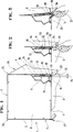
- . la figure 1 représente, en vue en perspective partielle, le caisson de volet roulant conforme à l'invention.
- . la figure 2 représente, en vue en perspective partielle, l'extrémité latérale du caisson dans laquelle est introduit un élément de manoeuvre.
- . la figure 3 représente, en vue en perspective partielle, l'extrémité latérale du caisson en phase de relèvement du panneau vertical interne.
- On se réfère aux trois figures.
- Le caisson de volet roulant 1 es t constitué de panneaux en matière plastique formant une enceinte dans laquelle est logé un arbre sur lequel s'enroule et duquel se déroule le tablier (non représenté).
- A cet effet, le caisson 1 est composé d'un panneau horizontal supérieur 2, d'un panneau horizontal intérieur 3 présentant une lumière 4 à travers laquelle se déplace le tablier entraîné par ledit arbre, d'un panneau vertical externe 5 et d'un panneau vertical interne 6. Les deux extrémités 7 du caisson 1 sont obturées par un couvercle latéral 8.
- Chaque panneau en matière plastique 2, 3, 5 et 6 est formé d'une paroi interne 9, située du côté de l'arbre, et d'une paroi externe 10. On relie les deux parois 9, 10 par des entretoises longitudinales 11, 12, 13, 14, 15, 16 parallèles entre elles et disposées perpendiculairement à la face interne 18 de la paroi interne 9 et à la face interne 19 de la paroi externe 10, étant entendu que ces entretoises 11 à 16 sont solidaires desdites faces internes 18, 19. L'entretoise d'extrémité par exemple 11 et 22 sert de chant 23 au panneau 2, 3, 5 et 6.
- L'assemblage des panneaux 2 à 6 est assuré par des liaisons 24, 25, 26, 27 dont une sera décrite ci-dessous, étant entendu que les quatre liaisons 24 à 27 sont identiques. La liaison 24 dont la description est faite concerne la liaison entre le panneau horizontal inférieur 3 et le panneau vertical interne 6. En effet, du fait qu'il est nécessaire d'accéder aux éléments logés dans le caisson 1, le panneau vertical interne 6 sert de trappe d'accès. A cet effet, on relève le panneau vertical interne 6 qui peut pivoter autour de la liaison 25 située entre le panneau horizontal supérieur 2 et l'extrémité supérieure 28 du panneau vertical interne 6.
- La liaison 24 est formée, d'une part, par une lèvre 29 faisant saillie par rapport à l'entretoise 22, c'est-à-dire par rapport au chant 23 du panneau horizontal inférieur 3 et, d'autre part, par une rainure 30 réalisée dans la face interne 18 de la paroi interne 9 du panneau vertical interne 6, cette rainure 30 étant parallèle au chant 2,1 dudit panneau vertical interne 6.
- Lors de l'assemblage des panneaux 2,3, 5 et 6, la lèvre 29 de l'un les panneaux vient s'emboîter dans la rainure 30 de l'autre panneau. Ainsi, la lèvre 29 du panneau horizontal inférieur 3 vient s'emboîter dans la rainure 30 du panneau vertical interne 6.
- Après assemblage, il est donc nécessaire de dissoudre la coopération des deux moyens 29, 30 de la liaison 24. Conformément à l'invention, le caisson 1 comporte au droit de cette liaison 24 des moyens de préhension 11 permettant ladite dissolution.
- Ces moyens de préhension 31 sont deux perçages 32 pratiqués après assemblage du caisson 1 dans le chant inférieur 30 du panneau vertical interne 6. Ces perçages 32 sont dirigés de bas vers le haut et présentent une certaine longueur. Ces perçages 32 sont situés chacun à proximité de chaque extrémité latérale du chant inférieur 23 du panneau vertical interne 6. Selon la largeur du caisson 1, on réalise des perçages intermédiaires entre les perçages 32. Ainsi, non seulement, le chant 23 est percé mais également plusieurs entretoises 12, 13, 14, 15 du panneau vertical interne 6.
- L'axe vertical 33 des perçages 32 est à une telle distance 34 de la paroi interne 9 du panneau vertical interne 6 que l'on perce également la lèvre 29 du panneau horizontal inférieur 3. Le trou 35 pratiqué dans la lèvre 29 débouche sur le chant 36 de cette lèvre saillante 29.
- On introduit dans ces perçages 32 un élément de manoeuvre 37 qui peut être à titre d'exemple non limitatif un tournevis à extrémité pointue ou autre élément pointu. La somme des résistances à la cassure de la pluralité des entretoises percées 11 12, 13 14, 15 est supérieure à la force nécessaire pour dégager la lèvre 29 de la rainure 30.
Claims (6)
- Caisson de volet roulant constitué de panneaux en matière plastique se composant d'un panneau horizontal supérieur (2) d'un panneau horizontal inférieur (3), d'un panneaux vertical externe (5), d'un panneau vertical interne (6) et de deux couvercles latéraux (8) obsturant les deux extrémités latérales (7) du caisson (1) chaque panneau (2, 3, 5 et 6) étant formé d'une paroi interne (9) et d'une paroi externe (10) reliée entre elles par des entretoises parallèles (11, 12, 13, 14, 15, 16) solidaires des faces internes (18, 19) de la paroi interne (9), respespectivement de la paroi externe (10), caisson (1) caractérisé en ce qu'il comporte au droit de la liaison (24) entre le panneau horizontal inférieur (3) et le panneaux vertical interne (6) des moyens de préhension (31) permettant la dissolution de cette liaison (24).
- Caisson selon la revendication 1 , caractérisé en ce que les moyens de préhension (31) assurant la dissolution de la liaison (24) entre le panneau horizontal inférieur (3) et le panneau vertical interne (6), liaison formée d'une lèvre (29) saillante du chant longitudinal (23) du panneau horizontal inférieur (3) et d'une rainure (30) réalisée dans la paroi interne (9) du panneau vertical interne (6), sont au moins deux perçages (32) pratiqués après assemblage du caisson (1) dans le chant inférieur (23) du panneau vertical interne (6) et dirigés de bas vers le haut.
- Caisson selon la revendication 2, caractérisé en ce que les deux perçages (32) sont situés chacun à proximité de chaque extrémité latérale du chant inférieur (23) du panneau vertical interne (6).
- Caisson selon la revendication 2, caractérisé en ce que les deux perçages (32) s'étendent depuis le chant inférieur (23) du panneau vertical interne (6) et traversent plusieurs entretoises parallèles (12, 13, 14, 15) reliant les faces internes (18, 19) de la paroi interne (9) et de la paroi externe (10) du panneau vertical interne (3).
- Caisson selon la revendication 2, caractérisé en ce que l'axe vertical (33) de perçage (32) est à une distance (34) de la paroi interne (9) du panneaux vertical interne (6) telle que le perçage (32) traverse la lèvre saillante (29) du panneau horizontal inférieur (3).
- Caisson selon la revendication 5, caractérisé en ce que le trou (35), réalisé dans la lèvre saillante (29) du panneau horizontal inférieur (3), débouche sur le chant ( 36) de cette lèvre saillante (29).
Applications Claiming Priority (2)
| Application Number | Priority Date | Filing Date | Title |
|---|---|---|---|
| FR9014709 | 1990-11-20 | ||
| FR9014709A FR2669372B1 (fr) | 1990-11-20 | 1990-11-20 | Caisson de volet roulant. |
Publications (2)
| Publication Number | Publication Date |
|---|---|
| EP0487436A1 true EP0487436A1 (fr) | 1992-05-27 |
| EP0487436B1 EP0487436B1 (fr) | 1994-09-21 |
Family
ID=9402568
Family Applications (1)
| Application Number | Title | Priority Date | Filing Date |
|---|---|---|---|
| EP91440084A Expired - Lifetime EP0487436B1 (fr) | 1990-11-20 | 1991-10-22 | Caisson de volet roulant |
Country Status (5)
| Country | Link |
|---|---|
| EP (1) | EP0487436B1 (fr) |
| AT (1) | ATE112012T1 (fr) |
| DE (1) | DE69104168T2 (fr) |
| ES (1) | ES2060336T3 (fr) |
| FR (1) | FR2669372B1 (fr) |
Cited By (1)
| Publication number | Priority date | Publication date | Assignee | Title |
|---|---|---|---|---|
| EP0740045A3 (fr) * | 1995-04-28 | 1998-04-08 | Johann Henkenjohann | Caisson pour volet roulant |
Citations (3)
| Publication number | Priority date | Publication date | Assignee | Title |
|---|---|---|---|---|
| DE2231626A1 (de) * | 1972-06-28 | 1974-01-10 | Karl Wohnhaas | Rolladenkasten zum nachtraeglichen einbau in wandoeffnungen |
| FR2375425A2 (fr) * | 1976-12-22 | 1978-07-21 | Le Bihan Et Le Mouel Sa | Coffre de volet roulant |
| DE2715910A1 (de) * | 1977-04-09 | 1978-10-19 | Hans Udo Reichstadt | Rolladen-kasten |
-
1990
- 1990-11-20 FR FR9014709A patent/FR2669372B1/fr not_active Expired - Fee Related
-
1991
- 1991-10-22 EP EP91440084A patent/EP0487436B1/fr not_active Expired - Lifetime
- 1991-10-22 DE DE69104168T patent/DE69104168T2/de not_active Expired - Fee Related
- 1991-10-22 AT AT91440084T patent/ATE112012T1/de not_active IP Right Cessation
- 1991-10-22 ES ES91440084T patent/ES2060336T3/es not_active Expired - Lifetime
Patent Citations (3)
| Publication number | Priority date | Publication date | Assignee | Title |
|---|---|---|---|---|
| DE2231626A1 (de) * | 1972-06-28 | 1974-01-10 | Karl Wohnhaas | Rolladenkasten zum nachtraeglichen einbau in wandoeffnungen |
| FR2375425A2 (fr) * | 1976-12-22 | 1978-07-21 | Le Bihan Et Le Mouel Sa | Coffre de volet roulant |
| DE2715910A1 (de) * | 1977-04-09 | 1978-10-19 | Hans Udo Reichstadt | Rolladen-kasten |
Cited By (1)
| Publication number | Priority date | Publication date | Assignee | Title |
|---|---|---|---|---|
| EP0740045A3 (fr) * | 1995-04-28 | 1998-04-08 | Johann Henkenjohann | Caisson pour volet roulant |
Also Published As
| Publication number | Publication date |
|---|---|
| FR2669372A1 (fr) | 1992-05-22 |
| ATE112012T1 (de) | 1994-10-15 |
| DE69104168T2 (de) | 1995-03-09 |
| FR2669372B1 (fr) | 1993-01-29 |
| DE69104168D1 (de) | 1994-10-27 |
| EP0487436B1 (fr) | 1994-09-21 |
| ES2060336T3 (es) | 1994-11-16 |
Similar Documents
| Publication | Publication Date | Title |
|---|---|---|
| CA2059422A1 (fr) | Dispositif de fermeture de l'extremite d'un profile | |
| EP0628695B1 (fr) | Dispositif de fermeture des extrémités latérales de coffres de volet roulant | |
| BE1009323A6 (fr) | Structure de decor repliable. | |
| EP0935562B1 (fr) | Boite d'emballage comportant un fond en carton et un couvercle transparent | |
| FR2608192A1 (fr) | Couverture repliable pour veranda ou abri similaire | |
| EP0487436A1 (fr) | Caisson de volet roulant | |
| EP2832949B1 (fr) | Système de commande de lames de jalousie et jalousie correspondante | |
| EP1524399B1 (fr) | Portillon de sécurité | |
| FR2614929A1 (fr) | Tablier pour volet roulant | |
| FR2593219A1 (fr) | Serrure a broche rotative dotee d'un pene transversal pour coffret | |
| EP1164083B1 (fr) | Emballage octogonal | |
| EP0684672A1 (fr) | Coffret notamment pour appareillage électrique basse tension | |
| EP2065538A1 (fr) | Abri pour bassin de piscine | |
| FR2765616A1 (fr) | Perfectionnements a des volets roulants | |
| EP0944791B1 (fr) | Joint destine a etre dispose circonferentiellement autour d'un element globalement cylindrique | |
| FR2755466A1 (fr) | Dispositif de montage d'un panneau coulissant | |
| BE1003318A3 (fr) | Sceau de securite. | |
| CH618495A5 (en) | Folding blind | |
| FR2854194A1 (fr) | Dispositif pour le coffrage de volet roulant, notamment pour construction legere, telle que veranda | |
| FR2705390A1 (fr) | Dispositif de protection pour ouvertures dans les murs ou analogues. | |
| FR2742187A1 (fr) | Volet roulant muni de moyens de blocage de la lame finale | |
| FR2581825A1 (fr) | Perfectionnements a la fermeture etanche des coffrets ou armoires | |
| FR2777939A1 (fr) | Grille metallique | |
| FR2618468A1 (fr) | Couvercle pour regard ou analogue | |
| FR2769040A1 (fr) | Persiennes coulissantes destinees a la fermeture de fenetres portes-fenetres ou portes |
Legal Events
| Date | Code | Title | Description |
|---|---|---|---|
| PUAI | Public reference made under article 153(3) epc to a published international application that has entered the european phase |
Free format text: ORIGINAL CODE: 0009012 |
|
| AK | Designated contracting states |
Kind code of ref document: A1 Designated state(s): AT BE CH DE DK ES GB GR IT LI LU NL SE |
|
| 17P | Request for examination filed |
Effective date: 19920918 |
|
| 17Q | First examination report despatched |
Effective date: 19930624 |
|
| GRAA | (expected) grant |
Free format text: ORIGINAL CODE: 0009210 |
|
| AK | Designated contracting states |
Kind code of ref document: B1 Designated state(s): AT BE CH DE DK ES GB GR IT LI LU NL SE |
|
| PG25 | Lapsed in a contracting state [announced via postgrant information from national office to epo] |
Ref country code: NL Effective date: 19940921 Ref country code: GR Free format text: LAPSE BECAUSE OF FAILURE TO SUBMIT A TRANSLATION OF THE DESCRIPTION OR TO PAY THE FEE WITHIN THE PRESCRIBED TIME-LIMIT Effective date: 19940921 Ref country code: GB Effective date: 19940921 Ref country code: DK Effective date: 19940921 Ref country code: AT Effective date: 19940921 |
|
| REF | Corresponds to: |
Ref document number: 112012 Country of ref document: AT Date of ref document: 19941015 Kind code of ref document: T |
|
| ITF | It: translation for a ep patent filed | ||
| REF | Corresponds to: |
Ref document number: 69104168 Country of ref document: DE Date of ref document: 19941027 |
|
| PG25 | Lapsed in a contracting state [announced via postgrant information from national office to epo] |
Ref country code: SE Effective date: 19941221 |
|
| NLV1 | Nl: lapsed or annulled due to failure to fulfill the requirements of art. 29p and 29m of the patents act | ||
| GBV | Gb: ep patent (uk) treated as always having been void in accordance with gb section 77(7)/1977 [no translation filed] |
Effective date: 19940921 |
|
| REG | Reference to a national code |
Ref country code: CH Ref legal event code: PUE Owner name: ETABLISSEMENTS BUBENDORFF SOCIETE ANONYME Ref country code: CH Ref legal event code: PLI Owner name: BUBENDORFF S.A. |
|
| ITPR | It: changes in ownership of a european patent |
Owner name: CESSIONE;ETABLISSEMENTS BUBENDORF S.A. |
|
| PLBE | No opposition filed within time limit |
Free format text: ORIGINAL CODE: 0009261 |
|
| STAA | Information on the status of an ep patent application or granted ep patent |
Free format text: STATUS: NO OPPOSITION FILED WITHIN TIME LIMIT |
|
| REG | Reference to a national code |
Ref country code: ES Ref legal event code: PC2A Owner name: ETABLISSEMENTS BUBENDORFF, S.A. |
|
| 26N | No opposition filed | ||
| PGFP | Annual fee paid to national office [announced via postgrant information from national office to epo] |
Ref country code: LU Payment date: 19951001 Year of fee payment: 5 |
|
| PG25 | Lapsed in a contracting state [announced via postgrant information from national office to epo] |
Ref country code: LU Free format text: LAPSE BECAUSE OF NON-PAYMENT OF DUE FEES Effective date: 19961022 |
|
| PGFP | Annual fee paid to national office [announced via postgrant information from national office to epo] |
Ref country code: CH Payment date: 19971106 Year of fee payment: 7 |
|
| PGFP | Annual fee paid to national office [announced via postgrant information from national office to epo] |
Ref country code: BE Payment date: 19971211 Year of fee payment: 7 |
|
| PG25 | Lapsed in a contracting state [announced via postgrant information from national office to epo] |
Ref country code: LI Free format text: LAPSE BECAUSE OF NON-PAYMENT OF DUE FEES Effective date: 19981031 Ref country code: CH Free format text: LAPSE BECAUSE OF NON-PAYMENT OF DUE FEES Effective date: 19981031 Ref country code: BE Free format text: LAPSE BECAUSE OF NON-PAYMENT OF DUE FEES Effective date: 19981031 |
|
| BERE | Be: lapsed |
Owner name: ETS BUBENDORFF S.A. Effective date: 19981031 |
|
| REG | Reference to a national code |
Ref country code: CH Ref legal event code: PL |
|
| PGFP | Annual fee paid to national office [announced via postgrant information from national office to epo] |
Ref country code: DE Payment date: 20061019 Year of fee payment: 16 |
|
| PGFP | Annual fee paid to national office [announced via postgrant information from national office to epo] |
Ref country code: IT Payment date: 20061031 Year of fee payment: 16 |
|
| PGFP | Annual fee paid to national office [announced via postgrant information from national office to epo] |
Ref country code: ES Payment date: 20061124 Year of fee payment: 16 |
|
| PG25 | Lapsed in a contracting state [announced via postgrant information from national office to epo] |
Ref country code: DE Free format text: LAPSE BECAUSE OF NON-PAYMENT OF DUE FEES Effective date: 20080501 |
|
| REG | Reference to a national code |
Ref country code: ES Ref legal event code: FD2A Effective date: 20071023 |
|
| PG25 | Lapsed in a contracting state [announced via postgrant information from national office to epo] |
Ref country code: ES Free format text: LAPSE BECAUSE OF NON-PAYMENT OF DUE FEES Effective date: 20071023 |
|
| PG25 | Lapsed in a contracting state [announced via postgrant information from national office to epo] |
Ref country code: IT Free format text: LAPSE BECAUSE OF NON-PAYMENT OF DUE FEES Effective date: 20071022 |