EP0487726B1 - Messvorrichtung für die blutströmungsgeschwindigkeit und des flussvolumens in der aorta - Google Patents
Messvorrichtung für die blutströmungsgeschwindigkeit und des flussvolumens in der aorta Download PDFInfo
- Publication number
- EP0487726B1 EP0487726B1 EP90909486A EP90909486A EP0487726B1 EP 0487726 B1 EP0487726 B1 EP 0487726B1 EP 90909486 A EP90909486 A EP 90909486A EP 90909486 A EP90909486 A EP 90909486A EP 0487726 B1 EP0487726 B1 EP 0487726B1
- Authority
- EP
- European Patent Office
- Prior art keywords
- blood flow
- pressure
- pulse wave
- period
- flow velocity
- Prior art date
- Legal status (The legal status is an assumption and is not a legal conclusion. Google has not performed a legal analysis and makes no representation as to the accuracy of the status listed.)
- Expired - Lifetime
Links
- 230000017531 blood circulation Effects 0.000 title claims abstract description 241
- 210000000709 aorta Anatomy 0.000 title claims abstract description 71
- 238000001514 detection method Methods 0.000 claims description 110
- 230000035487 diastolic blood pressure Effects 0.000 claims description 38
- 230000035488 systolic blood pressure Effects 0.000 claims description 35
- 230000008859 change Effects 0.000 claims description 20
- 230000003247 decreasing effect Effects 0.000 claims description 20
- 210000001367 artery Anatomy 0.000 claims description 19
- 230000007423 decrease Effects 0.000 claims description 8
- 230000003205 diastolic effect Effects 0.000 abstract 2
- 238000005259 measurement Methods 0.000 description 30
- 238000000034 method Methods 0.000 description 27
- 239000008280 blood Substances 0.000 description 13
- 210000004369 blood Anatomy 0.000 description 13
- 230000000717 retained effect Effects 0.000 description 12
- 238000004364 calculation method Methods 0.000 description 6
- 230000006870 function Effects 0.000 description 6
- 230000000644 propagated effect Effects 0.000 description 6
- 210000001765 aortic valve Anatomy 0.000 description 5
- 238000006243 chemical reaction Methods 0.000 description 5
- 230000004087 circulation Effects 0.000 description 5
- CURLTUGMZLYLDI-UHFFFAOYSA-N Carbon dioxide Chemical compound O=C=O CURLTUGMZLYLDI-UHFFFAOYSA-N 0.000 description 4
- 239000003153 chemical reaction reagent Substances 0.000 description 4
- 238000003745 diagnosis Methods 0.000 description 3
- 201000010099 disease Diseases 0.000 description 3
- 208000037265 diseases, disorders, signs and symptoms Diseases 0.000 description 3
- 210000004072 lung Anatomy 0.000 description 3
- 230000002093 peripheral effect Effects 0.000 description 3
- 230000008569 process Effects 0.000 description 3
- 238000012545 processing Methods 0.000 description 3
- 230000000630 rising effect Effects 0.000 description 3
- QVGXLLKOCUKJST-UHFFFAOYSA-N atomic oxygen Chemical compound [O] QVGXLLKOCUKJST-UHFFFAOYSA-N 0.000 description 2
- 210000004204 blood vessel Anatomy 0.000 description 2
- 229910002092 carbon dioxide Inorganic materials 0.000 description 2
- 239000001569 carbon dioxide Substances 0.000 description 2
- 238000010586 diagram Methods 0.000 description 2
- 239000012530 fluid Substances 0.000 description 2
- 230000000977 initiatory effect Effects 0.000 description 2
- 229910052760 oxygen Inorganic materials 0.000 description 2
- 239000001301 oxygen Substances 0.000 description 2
- 230000035485 pulse pressure Effects 0.000 description 2
- 230000029058 respiratory gaseous exchange Effects 0.000 description 2
- 230000009471 action Effects 0.000 description 1
- 238000004458 analytical method Methods 0.000 description 1
- 230000036772 blood pressure Effects 0.000 description 1
- 230000008602 contraction Effects 0.000 description 1
- 238000007796 conventional method Methods 0.000 description 1
- 230000001419 dependent effect Effects 0.000 description 1
- 238000005516 engineering process Methods 0.000 description 1
- 238000007689 inspection Methods 0.000 description 1
- 210000005246 left atrium Anatomy 0.000 description 1
- 210000005240 left ventricle Anatomy 0.000 description 1
- 238000012544 monitoring process Methods 0.000 description 1
- 210000004165 myocardium Anatomy 0.000 description 1
- 230000000737 periodic effect Effects 0.000 description 1
- 210000005245 right atrium Anatomy 0.000 description 1
- 210000005241 right ventricle Anatomy 0.000 description 1
- 238000004904 shortening Methods 0.000 description 1
- 210000003462 vein Anatomy 0.000 description 1
- 230000002861 ventricular Effects 0.000 description 1
Images


Classifications
-
- A—HUMAN NECESSITIES
- A61—MEDICAL OR VETERINARY SCIENCE; HYGIENE
- A61B—DIAGNOSIS; SURGERY; IDENTIFICATION
- A61B5/00—Measuring for diagnostic purposes; Identification of persons
- A61B5/02—Detecting, measuring or recording for evaluating the cardiovascular system, e.g. pulse, heart rate, blood pressure or blood flow
- A61B5/021—Measuring pressure in heart or blood vessels
- A61B5/022—Measuring pressure in heart or blood vessels by applying pressure to close blood vessels, e.g. against the skin; Ophthalmodynamometers
- A61B5/02208—Measuring pressure in heart or blood vessels by applying pressure to close blood vessels, e.g. against the skin; Ophthalmodynamometers using the Korotkoff method
-
- A—HUMAN NECESSITIES
- A61—MEDICAL OR VETERINARY SCIENCE; HYGIENE
- A61B—DIAGNOSIS; SURGERY; IDENTIFICATION
- A61B5/00—Measuring for diagnostic purposes; Identification of persons
- A61B5/02—Detecting, measuring or recording for evaluating the cardiovascular system, e.g. pulse, heart rate, blood pressure or blood flow
- A61B5/021—Measuring pressure in heart or blood vessels
- A61B5/022—Measuring pressure in heart or blood vessels by applying pressure to close blood vessels, e.g. against the skin; Ophthalmodynamometers
- A61B5/0225—Measuring pressure in heart or blood vessels by applying pressure to close blood vessels, e.g. against the skin; Ophthalmodynamometers the pressure being controlled by electric signals, e.g. derived from Korotkoff sounds
-
- A—HUMAN NECESSITIES
- A61—MEDICAL OR VETERINARY SCIENCE; HYGIENE
- A61B—DIAGNOSIS; SURGERY; IDENTIFICATION
- A61B5/00—Measuring for diagnostic purposes; Identification of persons
- A61B5/02—Detecting, measuring or recording for evaluating the cardiovascular system, e.g. pulse, heart rate, blood pressure or blood flow
- A61B5/026—Measuring blood flow
- A61B5/029—Measuring blood output from the heart, e.g. minute volume
-
- A—HUMAN NECESSITIES
- A61—MEDICAL OR VETERINARY SCIENCE; HYGIENE
- A61B—DIAGNOSIS; SURGERY; IDENTIFICATION
- A61B5/00—Measuring for diagnostic purposes; Identification of persons
- A61B5/02—Detecting, measuring or recording for evaluating the cardiovascular system, e.g. pulse, heart rate, blood pressure or blood flow
- A61B5/026—Measuring blood flow
- A61B5/0285—Measuring or recording phase velocity of blood waves
Definitions
- This invention relates to an apparatus for measuring a blood flow velocity, specifically an apparatus for detecting a passage of a pulse wave by a cuff put around an upper arm, and, based on this detection result, obtaining a blood flow velocity of the aorta.
- a method which has been conventionally used for measuring blood flow velocity and blood flow volume of aortas is blood vessel catheter measuring method in which a catheter is inserted into an aorta.
- a pair of pressure sensors are attached at a set interval to the leading end of the catheter.
- the catheter is inserted until its leading end reaches an aorta under X-ray inspection to detect pulse waves as a pressure change by both pressure sensors, whereby a blood flow velocity of the aorta is obtained based on a phase difference of the detected pulse waves.
- a blood flow volume is given by multiplying a blood flow effective sectional area of the aorta by the blood flow velocity.
- a reagent is poured from the leading end of the catheter to measure a lung circulation time of the reagent, whereby an averaged stroke volume per minute is given.
- This known device includes a volume measuring device secured to a specific part of a human being for measuring changes in the blood flow volume therethrough, and a pressure measuring device, also secured to the specific part and spaced from the volume measuring device at the pre-determined distance.
- Transducers convert the sensed volume and pressure values into electrical signals which are transmitted to suitable recording means whereby such recorded values, which are functions of time, may be utilized for determining the blood flow rate.
- this device comprises a forward sensor for detecting the forward pulse wave at a first point of an artery, a rear sensor for detecting a rear pulse wave at a second point on the artery, the first and second point being located with a distance therebetween so that the rear sensor detects the rear pulse after a delay time.
- the known device comprises calculating means for dividing the distance by a delay time to obtain a quotient and outputting the quotient as a blood flow velocity.
- An object of this invention is to provide an apparatus for measuring the blood flow velocity of an aorta by a non-invasive and simple method.
- the present invention is related to an apparatus for measuring a blood flow velocity in an aorta, comprising:
- the present invention is also related to an apparatus for measuring a blood flow velocity in an aorta, comprising:
- the present invention is also related to an apparatus for measuring a blood flow velocity in an aorta, comprising:
- the present invention is also related to an apparatus for measuring a blood flow volume in an aorta, comprising:
- the present invention is also related to an apparatus for measuring a blood flow volume in an aorta, comprising:
- the apparatus according to this invention is for measuring the blood flow velocity and blood flow volume of an aorta, and its primary characteristic lies in detecting pulse waves non invasively and obtaining a blood flow velocity and blood flow volume, based on the detected information.
- FIG. 1 shows the general waveform of pulse waves (aortic waves) observed in the aortas. As shown in FIG. 1, the waveform is shown by taking time on the horizontal axis and pressures on the vertical axis. The waveform of aortic waves is indicative of blood pressure changes near the heart, and represents a motion of the left ventricular myocardium as it is. This waveform gives very significant information for the diagnosis of circulatory diseases.
- the heart contracts, raising the pressure of the aorta up from a diastolic pressure DP to a systolic pressure SP. Subsequently the heart expands at the time t2. Resultantly from the time t2 to the time t3 a pressure of the aorta is decreased, but since the aortic valve closes at the time t3, a peak takes place. Resultantly a trough called dicroticnotch occurs at the time t3. The pressure at the time t3 is called dicroticnotch pressure DNP. After the time t4 the pressure is slowly decreased back to the diastolic pressure DP at the time t5.
- the process from the time t1 to the time t5 is periodically repeated every pulse of the heart.
- the period from the time t1 to the time t3 in which the aortic valve opens is called high pressure period T1
- the period from the time t3 to the time t5 in whcih the aortic valve closes is called low pressure period T2.
- FIG. 2 shows a model of the circulation passage of the blood.
- the blood which has taken in air in the lung 10 enters the left ventricle 12 from the left atrium 11 to be sent out into the arteries 14 through the aortic valve 13.
- This blood passes through the peripheral vessels 15 to supply the oxygen to cells, taking in carbon dioxide.
- the blood passes through the veins 16 and then into the right atrium 17 and the valvular tricuspidalis 18 back to the lung 10 from the right ventricle 19 to discharge the carbon dioxide and take in oxygen.
- This is the circulation passage of the blood.
- a pressure change in the arteries 14 is a pulse wave.
- the pulse wave varies depending on detection locations.
- the pulse wave is a pulse wave WA and corresponds to the aortic wave of FIG. 1.
- the pulse wave is detected as pulse waves WB to WE respectively at locations 14b to 14e of the artery.
- the pulse wave has the waveform having an increased high frequency component as the pulse wave WF. Accordingly the peak value of the pulse wave WF or peripheral systolic pressure PSP is higher than a systolic pressure SP.
- the blood flow velocity and blood flow volume to be measured by the apparatus according to this invention are blood flow velocity and blood flow volume in the aorta 14a.
- a catheter is inserted up to the aorta 14a to measure the blood flow velocity and volume.
- a characteristic of the apparatus according to this invention is that a blood flow velocity and blood flow volume in the aorta 14a can be given by putting a cuff around a part of an artery 14f near the periphery (e.g., an upper arm), and based on information of pulse waves detected by retaining the cuff at given pressures, obtaining a blood flow velocity and blood flow volume of the aorta 14a.
- FIG. 3 is a block diagram of a basic structure of the apparatus for measuring the blood flow velocity and volume according to one emobodiment of this invention.
- This apparatus largely comprises two component parts of an apparatus body 100 (enclosed by an one dot chain line), and a cuff 200.
- the cuff 200 includes a blood flow shutting bag 220 (indicated by an one dot chain line), a forward detection bag 210 (indicated by a broken line) for detecting a pulse wave heading to the blood flow shutting bag 220, and a rear detection bag 230 (indicated by a two dot chain line) for detecting a pulse wave which has cleared the blood flow shutting bag 220.
- the blood flow shutting bag 220 and the rear detection bag 230 are communicated with each other by an intermediate connection passage 225.
- a conduit 240 for passing air is extended outside from the forward detection bag 210, and similarly a conduit 250 is extended outside from the rear detection bag 230.
- This cuff 200 is put around an upper arm as viewed in FIG. 4. When air is fed into the respective bags of the cuff put around in this state to apply a pressure, an artery 300 is pressed by the respective bags as shown in the sectional view of FIG. 5 (in FIG.
- the respective bags are spaced from one another for the convenience of explanation but less spaced actually in the cuff).
- the pressure is raised sufficiently high, the blood flow of the artery 300 is completely shut.
- the blood flow shutting bag 220 has a large volume and high resistance, the high frequency component is prevented by the blood flow shutting bag 220 from reaching the rear detection bag 230.
- the pulse wave When the pulse wave is permitted to clear the blood flow shutting bag 220 as the pressure is decreased, the pulse wave clears the bag 220 to impinge on the rear detection bag 230.
- the forward detection bag 210 is always detecting a pulse wave, but the rear detection bag 230 detects a pulse wave only when the pulse wave clears the blood flow shutting bag 220.
- the apparatus body 100 has the following structure.
- a piping 102 connected to the conduit 240 is connected to a forward sensor 110
- a piping 101 connected to the conduit 250 is connected to a rear sensor 120.
- the forward sensor 110 measures a pressure of the forward detection bag 210
- the rear sensor 120 measures a pressure of the rear detection bag 230.
- the respective sensors are designed so as to sufficiently detect a frequency band of the pulse wave.
- An analog signal detected by the forward sensor 110 is amplified by an amplifier 111 and is converted to a digital signal by an A/D converter 112 to be supplied to a CPU 130.
- a signal detected by the forward sensor 120 is amplified by an amplifier 121 and is converted to a digital signal by an A/D converter 122 to be supplied to the CPU 130.
- An air pump 140 and a leak valve 150 are connected to the piping 102. The air pump 140 and the leak valve 150 are controlled by the CPU 130.
- the piping 101 and the piping 102 are interconnected, and the blood flow shutting bag 220 and the rear detection bag 230 are interconnected by the intermediate passage 225. Accordingly the blood flow shutting bag 220 and the detection bags 210, 230 intrinsically have the same pressure. But because of a large capacity and resistance of the blood flow shutting bag 220, a pressure change of a high frequency is found only by the forward detection bag 210 and the rear detection bag 230. Accordingly it is preferable that the forward sensor 110 and the rear sensor 120 are disposed near the conduit 102 and the conduit 101.
- a memory 160 for storing data, a display device 170 for displaying the data, and a printer 180 are connected to the CPU
- FIG. 6 shows a graph explaining the basic operation of this apparatus.
- this apparatus includes the air pump 140 and the leak valve 150 to control the pressure of the blood flow shutting bag 220 and the detection bags 210, 230. That is, when their pressure is raised, the air pump 140 is actuated to feed air into the bags, and when the presure is decreased, the leak valve 150 is opened to let out the air in the bags.
- the cuff 200 is put around an upper arm of a person to be measured as shown in FIG. 4, and a measurement initiating switch (not shown) is turned on.
- the graph of FIG. 6 shows changes of a pressure of the bags immediately after the initiation of a measuring operation. That is, when the operation is started, the CPU 130 actuates the air pump 140 to feed air into the bags to gradually raise a pressure in the bags (from Point A toward B in the graph).
- the blood flow shutting bag 220 gradually presses the artery, and soon its pressure reaches a pressure which completely shuts the blood flow (Point B).
- the relationship between the cuff 200 (the blood flow shutting bag 220 and both detection bags 210, 230) with the artery 300 at this time is shown by the sectional view of FIG. 8a.
- the left side of the view is the heart, and the right side of the view is the periphery, and a pulse wave is propagated from the left to the right.
- a high frequency component of the pulse wave can clear the forward detection bag 210, but none of the frequency components of the pulse wave can clear the blood flow shutting bag 220 because of a higher pressure of the blood flow shutting bag 220.
- the forward sensor 110 detects the pulse wave heading to the blood flow shutting bag 220, but the rear sensor 120 can detect none of the pulse wave.
- the pressure value at this time is maintained for a some time (Points B to C) to confirm the presence of air leakage of the bag. Then the CPU 130 slowly opens the leak valve 150 to decrease the pressure (from Point C toward D). Then a Korotkoff sound is generated at Point D.
- the waveform K in the graph indicates amplitudes of Korotkoff sounds of respective pulses obtained for respective pressure values when the pressure is gradually decreased from Point D (in this embodiment a sound wave sensor for detecting a Korotkoff sound is not included). It is because a part of the pulse wave 310 begins to clear the blood flow shutting bag 220 against a pressure of the blood flow shutting bag 220 as shown in FIG. 8b that a Korotkoff sound is generated past Point D.
- a pressure at Point D is a systolic pressure SP.
- the pulse wave 310 can clear the blood flow shutting bag 220 with more ease as shown in FIG. 8c, and the Korotkoff sound becomes maximum at Point E.
- the Korotkoff sound gradually diminishes, and at Point F the Korotkoff sound is very small and continuously has constant amplitudes.
- a pressure at Point F is a diastolic pressure DP, and this state corresponds to that of FIG. 8d.
- the Korotkoff sound dies out at Point G, and the pressure finally reaches Point H.
- the cuff 200 is afloat on the artery 300 as shown in FIG. 8e.
- a pulse wave is a change of an internal pressure of the artery 300 and accordingly is measured in a pressure value.
- a pulse wave propagated from the heart impinges first on the forward detection bag 210.
- the forward sensor 110 detects a pressure change due to this impingement of the pulse wave with the detection bag 210.
- the rear sensor 230 detects a pressure change due to the impingement of the pulse wave which has cleared the blood flow shutting bag 220.
- the amplitude of the pulse wave which clears the blood flow shutting bag 220 depends on a pressure of the bag 220.
- FIG. 6 shows this reference internal presure.
- Pressures actually detected by the sensors are the reference internal pressure multiplexed with pulse pressures.
- the reference internal pressure is decreased with time from Point C to Point D as shown in FIG. 6.
- a pressure value detected by the forward sensor 110 is, as shown in FIG. 7, the reference internal pressure (indicated by an one dot chain line) multiplexed with a pulse pressure (indicated by a broken line). Accordingly, the waveform of the pulse wave is given by subtracting the reference internal pressure from the detected pressure value of the sensor 110.
- FIG. 9 shows various waveforms of pulse waves detected from Point D to Point H in the graph of FIG. 6.
- the broken line waveforms are of a pulse wave detected by the forward sensor 110 (hereinafter called forward pulse wave).
- the solid line waveforms are of a pulse wave detected by the rear sensor 120 (hereinafter called rear pulse wave).
- the letters above the respective pulse waves indicate that the pulse waves were detected at points indicated by the letters in the graph of FIG. 6.
- the absence of a letter above a pulse wave means that the pulse wave was detected intermediate between points with the letters above.
- the apparatus For the measurement of a blood flow velocity of the aorta in the high pressure period, based on this innovational measurement principle, the apparatus according to this embodiment is operated as follows.
- the cuff 200 is put around an upper arm of a person to be measured, and the reference internal pressure of the respective bags is changed to those at Points A, B, C and D along the graph of FIG. 6.
- a pressure at this time (a systolic pressure SP) is retained for some time.
- the arrival of the pressure at Point D can be recognized by the rear sensor 120 beginning to detect a rear pulse wave.
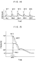
- a time difference between a forward pulse wave detected by the forward sensor 110, and a rear pulse wave detected by the rear sensor 120 is measured.
- FIG. 11 shows at the lower part a sectional view of the artery 300 whose blood flow is shut by the respective detection bags 210, 220, 230 having the reference internal pressure retained at a systolic pressure SP.
- the pulse wave When a pulse wave is propagated from the left to the right, the pulse wave first impinges on the forward detection bag 210. A part of the pulse wave clears the pressing blood flow shutting bag 220 to impinge on the rear detection bag 230.
- the detected pulse wave at this time is shown upper in FIG. 11.
- the broken line positions of the detection bags indicate those of the detection bags retained at the reference internal pressure (a systolic pressure SP).
- the one dot chain line positions of the detection bags indicate those of the detection bags pushed up by the passing pulse wave (at this time a detected pressure is SP').
- the forward pulse wave Wf is detected by the forward detection bag 210
- the rear pulse wave Wb is detected by the rear detection bag 230. Since FIG.
- FIG. 11 shows a state of a pulse wave being propagated from the left to the right, the waveform of the pulse wave is horizontally reversed to that in FIG. 10 (in FIG. 10 time is taken on the horizontal axis, but in FIG.11 spacing is taken on the horizontal axis).
- the rear pulse wave Wb is propagated over a distance L to be detected by the rear detection bag 230. Accordingly the rear pulse wave Wb is detected behind the forward pulse wave Wf by a delay time SPdt which the pulse wave takes to travel.
- the inventor of the present application has thus found that the propagation speed Vsp is approximate to a blood flow velocity VH of the aorta in the high pressure period. In this way, this apparatus enables an approximate value of a blood flow velocity of the aorta in the high pressure period to be given.
- a propagation velocity Vdp of a pulse wave clearing the pressing cuff when the pressure of the cuff (the reference internal pressure of the bags) is retained at a diastolic pressure DP is equal to a pulse wave propagation velocity at a part with the cuff put around. Accordingly by conduction the same measurement as described above with the reference internal pressure retained at a diastolic pressure DP, a pulse wave propagation velocity can be also measured.
- a blood flow velocity VL VH/R
- R (SP-DP)/(DNP-DP) .
- SP, DP and DNP respectively represent a systolic pressure, diastolic pressure and dicroticnotch pressure.
- a blood flow velocity in the high pressure period T1 is R times a blood flow velocity in the low pressure period T2.
- a blood flow velocity VL in the low pressure period can be given using Equation (2).
- a blood flow velocity VL thus given by the conversion and the result of the actual measurement obtained by inserting a catheter into the aorta agree with each other with considerably high experimental precision.
- This apparatus has a function of detecting an approximate aortic wave as shown in FIG. 1, and these pressure values can be given from the approximate aortic wave.
- the function of detecting an approximate aortic wave will be explained later in good detail.
- SH and SL represent blood flow effective sectional areas respectively in the high pressure period T1 and in the low pressure period T2
- VH and VL represent blood flow velocity respectively in the high pressure period T1 and in the low pressure period T2. Since the blood flow velocities VH, VL can be given by the above described methods, a blood flow volume Q per pulse can be calculated by Equation (5) if blood flow effective sectional areas SH, SL are known.
- the blood flow effective sectional area of the aorta will be considered.
- a characteristic of the blood flow results from periodic pulse waves.
- the section of the aorta is perfectly circular, the sectional area of this circle varies with time, based on aortic waves. This will be explained with reference to FIG. 12.
- a section of the aorta is shown on the left side of FIG. 12, and on the right side is shown an aortic wave WA.
- the pressure of the vessel wall of the aorta has a diastolic pressure DP.
- the section of the aorta is an rDP radius circle as shown on the left side of FIG.
- the vessel section of the aorta follows the process of expanding from the rDP radius circle to the rSP radius circle at every pulse of the heart, and returning to the rDP radius circle.
- the hatched portion with oblique lines is an expanded region due to a pulse wave. It is considered that only this region is a blood flow effective section which contributes to the flow of the blood. This is because only pulse waves cause the blood to flow. Without pulse waves, the section of the aorta is the shaded portion with dots in FIG. 12 (inside of the rDP radius circle), and the blood stagnates in this portion. Accordingly a blood flow effective area is an area of the hatched portion with oblique lines, and this area varies with a time and in accordance with an aortic wave WA.
- blood flow effective sectional areas SH in the high pressure period T1 and that SL in the low pressure period T2 are given as follows.
- an aortic wave WA is bisected in two portion of the high pressure period T1 and the low pressure period T2, and integrated values S1, S2 for the respective portions (corresponding to an area of the hatched portion with oblique lines) are calculated.
- the blood flow effective section for the high pressure period T1 is an rT1 radius circle C1
- that for the low pressure period T2 is an rT2 radius circle C2.
- an average blood flow effective sectional area SH for the high pressure period T1 and that SL for the low pressure period T2 can be defined as follows.
- SH ⁇ x rT1 2
- SL ⁇ x rT2 2
- the pulse wave of the upper arm (e.g., the pulse wave WF) is different from the aortic wave WA.
- the inventor of the present application has found that a pulse wave detected by the rear detection bag 230 when the blood flow shutting bag 220 is retained at a diastolic pressure DP is approximate to an aortic wave although the pulse wave is detected on the upper arm. It is difficult to theoretically analyze the reason for this precisely, but the inventor of the present application thinks that the blood flow shutting bag 220 functions as a low pass filter to cut off a high frequency component of the pulse wave. As shown in FIG. 2, a pulse wave has a high frequency component increased as it further travels to the periphery.
- the high frequency component is cut off when the pulse wave (pulse wave WF) of an upper arm clears the blood flow shutting bag 220 and is filtered into a pulse wave approximate to an aortic wave WA. Accordingly it is necessary that the blood flow shutting bag 220 has a width sufficient to function as the low pass filter, but it has been experimentally confirmed that for this function its width equal to or larger than 9 cm is sufficient for the general standard body. Since a pulse wave approximate to an aortic wave can be obtained when a pressure of the blood flow shutting bag 220 is equal to a diastolic pressure DP, the reference internal pressure is maintained constant when it has reached a diastolic pressure DP at Point F in the graph of FIG.
- a rear pulse wave is detected while the reference internal pressure is being maintained at the diastolic pressure DP.
- the detected rear pulse wave can be taken as an aortic wave. That is, in FIG. 9, the rear pulse indicated by the solid line at F is an approximate aortic wave.
- FIG. 9 is a view of forward pulses (broken line) and rear pulses (solid line) obtained when a pressure value of a blood flow shutting bag 220 is changed.
- FIG.9 suggests an effective method for judging whether the reference internal pressure of the cuff has reached Point F, i.e., whether or not a pressure value has decreased to a diastolic pressure DP.
- a forward pulse wave (broken line) and a rear pulse wave (solid line) detected at Point F have the lower parts perfectly agreed with each other.
- the reference internal pressure of the cuff is a diastolic pressure DP.
- FIG. 15 is a view explaining the comparison between the forward pulse wave Wf3 and the rear pulse wave Wb3 in good detail.
- the rear pulse wave Wb3 is behind the forward pulse wave Wf3 by a delay time DPdt, but the forward pulse wave Wf3 is moved to Wf3' so that the rising parts of both pulse waves agree with each other, and the lower parts of the pulse wave Wf3' and the pulse wave Wb3 are compared with each other.
- the parts of pulse waves below a dicroticnotch pressure DNP are compared as the lower parts.
- the part of the waveforms below the dicroticnotch pressure DNP are in perfect agreement with each other. But since actually such perfect agreement cannot be expected, it is preferable that agreements with a given error (e.g., an error equal to or lower than ⁇ 3%) are judged "Agreement".
- a rear pulse wave obtained at a time when "Agreement" is thus judged is an approximate aortic wave.
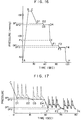
- the leak valve 150 is opened at Point C to decrease the reference internal pressure at a given rate (e.g., 2 mmHg/sec) from Point C to Point H.
- a given rate e.g. 2 mmHg/sec
- Point D where the reference internal pressure has reached a systolic pressure SP
- Point F where the reference internal pressure has reached a diastolic pressure DP
- a propagation velocity of a pulse wave clearing the cuff is obtained.
- the propagation velocity is given as a quotient obtained by dividing a distance L between the forward detection bag 210 and the rear detection bag 230 by a delay time SPdt of a rear pulse wave with respect to a forward pulse wave. This velocity is a high pressure period blood flow velocity VH of the aorta.
- the arrival of the reference internal pressure at Point D is recognized at a time when the rear detection bag 230 detects the pulse wave for the first time.
- waveform of the rear pulse wave at point F is recorded as a waveform of the approximate aortic wave.
- the arrival of the reference internal pressure at Point F is recognized by the agreement of the lower part of the forward pulse wave with that of the rear pulse wave with a given precision.
- a mere calculation processing follows the above described processing to determine all the necessary values. That is, since a diastolic pressure DP and a systolic pressure SP have been already given, and an approximate waveform of an aortic wave has been recorded, a dicroticnotch pressure DNP and pressure values in the high and low pressure periods T1, T2 can be determined.
- a low pressure period blood flow velocity VL can be given by Equation (2), and a blood flow volume per pulse Q is given by Equation (5).
- the forward sensor 110 detects a forward pulse wave, but the rear sensor 120 has not yet detected a rear pulse wave. But as the pressure is lowered, soon the rear sensor 120 detects a rear pulse wave for the first time. This point is Point D1 of the graph.
- the CPU 130 closes the leak valve 150 to retain a pressure SP1 at this time for a given measuring period (Point D1 to Point D2 of the graph).
- the leak valve 150 is instantaneously opened so as to lower the pressure by a trace of amount (e.g., 3 mmHg), and again this pressure SP2 is maintained for a given measuring period (Point D3 to Point D4 of the graph).
- a pressure value dP is preset constant (e.g., 30 mmHg). Since a next job of the CPU 130 is to recognize a diastolic pressure DP, the pressure is rapidly lowered from Point D4 to Point I so that a diastolic pressure DP can be obtained fastly. At Point I, the lower parts of the forward pulse wave and of the rear pulse wave have not yet agreed with each other. But as the pressure is lowered, soon the agreement within a set error range is detected between both pulse waves. This is found at Point F1. When the agreement within a set error range is found for the first time, the CPU 130 closes the leak valve 150 to maintain a pressure DP1 at this time for a set measuring period of time (from Point F1 to Point F2).
- the leak valve 150 When the measuring period has passed, the leak valve 150 is instantaneously opened to lower the pressure by a trace of amount (e.g., 3 mmHg), and again a pressure DP2 is retained for a set measuring period of time (Point F3 to Point F4 in the graph). This operation is repeated until the condition for determining a diastolic pressure DP (which will be explained later) is satisfied (repeated twice in the graph of FIG. 16). When the condition for determining a diastolic pressure DP is satisfied, the leak valve 150 is opened to decrease the pressure rapidly (Point F4 to Point H in the graph). What has been described above is the total procedure of the actual measuring operation of this apparatus.
- a trace of amount e.g., 3 mmHg
- FIG. 17 is a graph of pressure values detected by the respective sensors in accordance with the measuring operation shown in the graph of FIG. 16.
- Points C, D1 to D4, I, and F1 to F4 correspond to the respective points in the graph of FIG. 16, and the broken line depicts forward pulse waves detected by the forward sensor 110, and the solid line depicts rear pulse waves detected by the rear sensor 120.
- a set measuring period of time in which a pressure is retained constant is a period corresponding to three pulses, but actually it is preferable to set a period of time of 10 or more pulses.
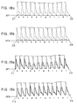
- FIG. 18a to 19b show detection results for measuring periods of time each of 12 pulses.
- FIG. 18a is a graph of pulse waves detected in Periods D1 to D2
- FIG. 18b is a graph of pulse waves detected in Periods D3 to D4
- FIG. 19a is a graph of pulse waves detected in Periods F1 to F2
- FIG. 19b is a graph of pulse waves detected in Periods F3 to F4.
- forward pulse waves are depicted by borken lines
- rear pulse waves are depicted by solid lines.
- the detected pulse waves have deviations although a pressure of the cuff is maintained constant.
- the one dot chain line connecting the peak positions of the forward pulse waves clearly indicate the deviations. These deviations largely result from respirations of a person to be measured. Accordingly to obtain measuring results of high precision, it is preferable to set a measuring period of at least one respiration period.
- a pressure is gradually lowered from Point C in the graph of FIG. 16 to recognize Point D1 where a rear pulse wave is detected for the first time.
- the judgement "whether or not a rear pulse wave has been detected” is actually to judge whether or not the peak value of a pulse wave outputted from the rear sensor 120 has exceeded a set "detection threshold value”.
- a pressure SP1 at Point D1 is maintained for a measuring period of time of 12 pulses (Points D1 to D2). The passage of this period of time can be recognized easily by counting 12 forward pulse waves.
- the pulse waves detected during this period of time are as shown in FIG. 18a.
- the forward pulse waves (broken lines) are clearly detected, but the rear pulse waves (solid lines) are so small that all the rear pulse waves have not exceeded a "detection threshold value".
- a detection accuracy is 5/12.
- a detection accuracy is obtained, and when a detection accuracy exceeds a preset detection accuracy, the condition for determining a systolic pressure SP has been satisfied. If the allowance for the detection accuracy is preset at 8/12, the above described measurement at SP1 has not satisfied the condition for determining a systolic pressure SP.
- a pressure of the cuff is a little lowered, a pulse wave can clear the pressing cuff with more ease, and a little generally larger pulse wave can be detected. If it is assumed that at this time eleven pulse waves out of 12 rear pulse waves a to l except a rear pulse wave e have exceeded a "detection threshold value", the detection accuracy is 11/12, which exceeds an allowance of 8/12. Accordingly the condition for determining a systolic pressure SP has been satisfied. The measuring operation can proceed to a next measuring step for determining a diastolic pressure DP.
- a value of systolic pressure SP which is finally determined, is an average of pressure values SP1 and SP2.
- a delay time SPdt to be used in determining a high pressure period blood flow velocity VH in an aortic wave is an average between a delay time obtained in the measurement at the pressure SP1 and a delay time obtained in the measurement at the pressure SP2.
- a diastolic pressure DP is performed by the following method.
- the pressure is gradually lowered from Point I in the graph of FIG. 16 to recognize Point F1 where the lower parts of both pulse waves agree with each other within a set allowance for error.
- the pressure DP1 at this point is maintained, and a measuring period of time of 12 pulses is taken (Point F1 to Point F2).
- the passage of this measuring period of time can be easily recognized by counting twelve forward pulse waves.
- the pulse waves detected during this measuring period of time are exemplified in FIG. 19a. All twelve pairs of forward and rear pulse waves do not always exhibit the agreement within the set allowance for error.
- the agreement accuracy is 5/12.
- An allowance value for this agreement accuracy is preset, and when an agreement accuracy exceeds this allowance, it is judged that the condition for determining a diastolic pressure DP is satisfied. If the allowance for the agreement accuracy is set at 8/12, the above described measurement at the pressure DP1 has not yet satisfied the condition for determining the diastolic pressure DP. Then the pressure is a little lowered to repeat the measurement at the pressure DP2.
- results of this measurement is shown in FIG. 19b.
- a final value of the diastolic pressure DP can be an average of the pressures DP1 and DP2.
- the waveform of an approximate aortic wave can be an average of a plurality of rear pulse waveforms.
- Various data can be obtained by the above described measuring operation.
- the data are stored in the memory 160 so that effective data for diagnoses can be displayed on the display device 170 or can be outputted to the printer 180.
- the following information are outputted as the measuring results.
- a systolic pressure SP and a diastolic pressure DP are recognized based on pulse waves detected by the pressure sensors. But it is possible to recognize them based on Korotkoff sounds detected by a sound wave sensor. That is, as indicated by the waveform K in FIG. 6, as the cuff pressure is decreased, at a systolic pressure SP a Korotkoff sound begins to be generated, and when the pressure exceeds a diastolic pressure DP the amplitude of the korotkoff sound becomes constant. Accordingly by monitoring the Korotkoff sounds by a sound wave sensor, the arrival at a systolic pressure SP and a diastolic pressure DP can be recognized.
- the blood flow velocity and blood flow volume measuring apparatus disclosed in the present application is usable for the diagnosis of circulaton diseases. Since this apparatus can provide measurement results simply by putting around the cuff on an upper arm and is very useful compared with the conventional invasive measuring methods. This invention will much contribute to the present medical diagnostic technology.
Landscapes
- Health & Medical Sciences (AREA)
- Life Sciences & Earth Sciences (AREA)
- Cardiology (AREA)
- Vascular Medicine (AREA)
- Biomedical Technology (AREA)
- Molecular Biology (AREA)
- Physiology (AREA)
- Biophysics (AREA)
- Pathology (AREA)
- Engineering & Computer Science (AREA)
- Veterinary Medicine (AREA)
- Heart & Thoracic Surgery (AREA)
- Medical Informatics (AREA)
- Physics & Mathematics (AREA)
- Surgery (AREA)
- Animal Behavior & Ethology (AREA)
- General Health & Medical Sciences (AREA)
- Public Health (AREA)
- Ophthalmology & Optometry (AREA)
- Hematology (AREA)
- Measuring Pulse, Heart Rate, Blood Pressure Or Blood Flow (AREA)
Claims (6)
- Vorrichtung zum Messen einer Blutströmungsgeschwindigkeit in einem lebenden Körper, umfassend:a) einen vorderen Sensor (110) zum Nachweisen einer vorderen Pulswelle (Wf) an einem ersten Punkt auf einer Arterie;b) einen hinteren Sensor (120) zum Nachweisen einer hinteren Pulswelle (Wb) an einem zweiten Punkt auf der Arterie, wobei der erste und der zweite Punkt einen Abstand L voneinander haben, so daß der hintere Sensor die hintere Pulswelle mit einer Zeitverzögerung dt, nachdem der vordere Sensor die vordere Pulswelle erfaßt hat, feststellt; undc) eine Berechnungseinrichtung (130) zum Dividieren des Abstands L durch die Zeitverzögerung dt, um einen Quotienten zu bilden und den Quotienten als Blutströmungsgeschwindigkeit auszugeben,dadurch gekennzeichnet, daß die Vorrichtung außerdem aufweist:d) eine Manschette (200) mit drei Taschen, bestehend aus einer Blutstromsperrtasche (220) zum Sperren eines Blutstroms in einem Oberarm, einer vorderen Nachweistasche (210) zum Nachweisen einer zu der Blutstromsperrtasche strebenden Pulswelle, und einer hinteren Nachweistasche (230) zum Nachweisen einer Pulswelle, die an der Blutstromsperrtasche vorbeigelangt ist, wobei eine in der vorderen Nachweistasche erzeugte Druckänderung als vordere Pulswelle (Wf) von dem vorderen Sensor erfaßt wird, und eine in der hinteren Nachweistasche erzeugte Druckänderung als hintere Pulswelle (Wb) von dem hinteren Sensor erfaßt wird; unde) eine Drucksteuereinrichtung (130, 140, 150) zum allmählichen Verringern eines Referenz-Innendrucks der Blutstromsperrtasche und der jeweiligen Nachweistaschen von einem ausreichend hohen Druck ausgehend, um einen Blutstrom zu sperren und um den Referenz-Innendruck als einen Druck SP zu halten, wenn der hintere Sensor zum ersten Mal eine hintere Pulswelle nachweist;f) wobei die Berechnungseinrichtung eine Division vornimmt, indem sie den Abstand L durch eine Zeitverzögerung SPdt dividiert, die erhalten wird, wenn die Drucksteuereinrichtung den Referenzinnendruck auf dem Druck SP halt, um einen Quotienten zu bilden und den Quotienten als Blutströmungsgeschwindigkeit VH einer Aorta in einer Zeitspanne hohen Drucks auszugeben.
- Vorrichtung zum Messen einer Blutströmungsgeschwindigkeit in einem lebenden Körper gemäß Anspruch 1, wobei die Vorrichtung weiterhin aufweist:a) eine Einrichtung (130) zum Erhalten eines systolischen Drucks SP, eines diastolischen Drucks DP und eines Dikrotik-Kerben-Drucks DNP;b) wobei die Berechnungseinrichtung eine zusätzlichen Funktion zum Berechnen eines Koeffizienten R anhand der Gleichung

- Vorrichtung zum Messen einer Blutströmungsgeschwindigkeit in einem lebenden Körper nach Anspruch 1, gekennzeichnet durch:a) eine Übereinstimmungs-Beurteilungseimichtung (130) zum Verzögern der vorderen Pulswelle um die Verzögerungszeit dt, um die vordere Pulswelle der hinteren Pulswelle zu überlagern, und um zu beurteilen, ob die unteren Teile der beiden Pulswellen miteinander bei eingestellter Genauigkeit übereinstimmen oder nicht;b) wobei die Drucksteuereirrichtung eine zusätzliche Funktion aufweist, um den Referenz-Innendruck allmählich zu verringern, nachdem eine erste Zeitspanne zum Halten des Referenz-Innendrucks auf dem Druck SP vonüber ist, und um den Referenz-Innendruck als einen Druck DP während seiner zweiten Zeitspanne zu halten, wenn die Übereinstimmungs-Beurteilungseimichtung Übereinstimmung feststellt; undc) wobei die Berechnungseinrichtung eine zusätzliche Funktion aufweist, um eine von dem hinteren Sensor nachgewiesene hintere Pulswelle in der zweiten Zeitspanne, als angenäherte Aortenwelle in der Nähe des Herzens zu erkennen, um einen systolischen Druck SP, einen diastolischen Druck DP und einen Dikrotik-Kerben-Druck DNP auf der Grundlage der angenäherten Aortenwelle zu erhalten, einen Koeffizienten R anhand der Gleichung

- Vorrichtung zum Messen eines Blutströmungsdurchsatzes, die die Vorrichtung nach Anspruch 3 beinhaltet;a) dadurch gekennzeichnet, daß die Berechnungseinrichtung die weitere zusätzliche Funktion aufweist, umb) eine wirksame Blutströmungsquerschnittsfläche SH der Aorta in der Zeitspanne hohen Drucks zu bilden aus der Zeit T1 mit Hilfe der Gleichung
 c) die Blutströmungsgeschwindigkeit VH in dem Zeitraum hohen Drucks zu multiplizieren mit der wirksamen Blutströmungsquerschnittsfläche SH in der Zeitspanne hohen Drucks, um ein Produkt zu bilden; undd) das gebildete Produkt als Blutströmungsdurchsatz in der Zeitspanne hohen Drucks auszugeben.
 - Vorrichtung zum Messen eines Blutströmungsdurchsatzes, die die Vorrichtung nach Anspruch 3 enthält;a) dadurch gekennzeichnet, daß die Berechnungseinrichtung die weitere Funktion aufweist, umb) eine wirksame Blutströmungsquerschnittsfläche SL der Aorta in der Zeitspanne niedrigen Drucks der Zeit T2 durch die Gleichung
 c) die Blutströmungsgeschwindigkeit VL in der Zeitspanne niedrigen Drucks zu multiplizieren mit der wirksamen Blutströmungsquerschnittsfläche SL in der Zeitspanne niedrigen Drucks, um ein Produkt zu bilden; undd) das erhaltene Produkt als Blutströmungsdurchsatz in der Zeitspanne niedrigen Drucks auszugeben.
 - Vorrichtung zum Messen eines Blutströmungsdurchsatzes, die die Vorrichtung gemäß Anspruch 3 enthält;
dadurch gekennzeichnet, daß die Berechnungseinrichtung die weitere Funktion aufweist, uma) eine wirksame Blutströmungsquerschnittsfläche SH der Aorta in der Zeitspanne hohen Drucks in der Zeit T3 zu bilden anhand der Gleichung b) die Blutströmungsgeschwindigkeit VH in der Zeitspanne hohen Drucks zu multiplizieren mit der wirksamen Blutströmungsquerschnittsfläche SH in der Zeitspanne hohen Drucks, um ein erstes Produkt zu bilden;c) eine wirksame Blutströmungsquerschnittsfläche SL der Aorta in der Zeitspanne niedrigen Drucks der Zeit T2 zu erhalten anhand der Gleichung
 d) die Blutströmungsgeschwindigkeit VL in der Zeitspanne niedrigen Drucks zu multiplizieren mit der wirksamen Blutströmungsquerschnittsfläche SL in der Zeitspanne niedrigen Drucks, um ein zweiten Produkt zu bilden;e) das erste Produkt und das zweite Produkt zu addieren, um eine Summe zu bilden; undf) die gebildete Summe als einen Blutströmungsdurchsatz Q pro Puls anzugeben.
Applications Claiming Priority (1)
| Application Number | Priority Date | Filing Date | Title |
|---|---|---|---|
| PCT/JP1990/000813 WO1991019451A1 (fr) | 1990-06-19 | 1990-06-19 | Dispositif de mesure de la vitesse et du volume du debit sanguin dans l'aorte |
Publications (3)
| Publication Number | Publication Date |
|---|---|
| EP0487726A1 EP0487726A1 (de) | 1992-06-03 |
| EP0487726A4 EP0487726A4 (en) | 1992-08-26 |
| EP0487726B1 true EP0487726B1 (de) | 1996-09-11 |
Family
ID=13986595
Family Applications (1)
| Application Number | Title | Priority Date | Filing Date |
|---|---|---|---|
| EP90909486A Expired - Lifetime EP0487726B1 (de) | 1990-06-19 | 1990-06-19 | Messvorrichtung für die blutströmungsgeschwindigkeit und des flussvolumens in der aorta |
Country Status (5)
| Country | Link |
|---|---|
| US (1) | US5301675A (de) |
| EP (1) | EP0487726B1 (de) |
| JP (1) | JP2877951B2 (de) |
| DE (1) | DE69028538T2 (de) |
| WO (1) | WO1991019451A1 (de) |
Families Citing this family (29)
| Publication number | Priority date | Publication date | Assignee | Title |
|---|---|---|---|---|
| US5316005A (en) * | 1990-05-17 | 1994-05-31 | Mitsuei Tomita | Apparatus for detecting and displaying blood ciculatory information |
| JP3006123B2 (ja) * | 1991-03-18 | 2000-02-07 | ソニー株式会社 | 動脈硬さ観測装置 |
| US5766130A (en) * | 1994-08-16 | 1998-06-16 | Selmonosky; Carlos A. | Vascular testing method |
| FR2726457B1 (fr) * | 1994-11-08 | 1998-08-28 | Lavoisier Pierre | Procede de mesure concernant la rigidite d'un penis et dispositif pour la mise en oeuvre de ce procede |
| JP3602880B2 (ja) * | 1995-02-17 | 2004-12-15 | コーリンメディカルテクノロジー株式会社 | 末梢循環状態監視装置 |
| AU722135B2 (en) * | 1995-03-17 | 2000-07-20 | Atcor Medical Pty Ltd | Non-invasive determination of aortic flow velocity waveforms |
| AUPN179895A0 (en) * | 1995-03-17 | 1995-04-13 | Pwv Medical Pty Ltd | Non-invasive determination of aortic flow velocity waveforms |
| US6010457A (en) * | 1996-03-15 | 2000-01-04 | Pmv Medical Pty Ltd | Non-invasive determination of aortic flow velocity waveforms |
| DE69618187T2 (de) * | 1996-08-14 | 2002-08-22 | Colin Corp., Komaki | Gerät zur Überwachung der peripherischen Blutströmung |
| WO1999063883A1 (en) * | 1998-06-11 | 1999-12-16 | S.P.O. Medical Equipment Ltd. | Physiological stress detector device and method |
| IL124787A0 (en) * | 1998-06-07 | 1999-01-26 | Itamar Medical C M 1997 Ltd | Pressure applicator devices particularly useful for non-invasive detection of medical conditions |
| US6331162B1 (en) | 1999-02-01 | 2001-12-18 | Gary F. Mitchell | Pulse wave velocity measuring device |
| US6196971B1 (en) * | 1999-04-02 | 2001-03-06 | Agilent Technologies, Inc. | Chord propagation velocity measurement system and method for an ultrasound imaging system |
| IL130939A (en) * | 1999-07-14 | 2005-11-20 | Itamar Medical Ltd | Probe devices particularly useful for non-invasivedetection of medical conditions |
| WO2001035822A1 (en) | 1999-11-12 | 2001-05-25 | Mitsuei Tomita | Device for detecting pain sensation |
| JP3400417B2 (ja) * | 2000-08-11 | 2003-04-28 | 日本コーリン株式会社 | 中枢動脈圧波形推定装置 |
| US6585660B2 (en) * | 2001-05-18 | 2003-07-01 | Jomed Inc. | Signal conditioning device for interfacing intravascular sensors having varying operational characteristics to a physiology monitor |
| JP3631979B2 (ja) * | 2001-06-06 | 2005-03-23 | コーリンメディカルテクノロジー株式会社 | 心機能評価機能付き血圧測定装置 |
| US7192403B2 (en) * | 2001-08-17 | 2007-03-20 | Russell Ted W | Methods, apparatus and articles-of-manufacture for noninvasive measurement and monitoring of peripheral blood flow, perfusion, cardiac output biophysic stress and cardiovascular condition |
| US7491173B2 (en) * | 2001-10-10 | 2009-02-17 | Team Medical, Llc | Method and system for obtaining dimension related information for a flow channel |
| US6540688B1 (en) | 2001-10-11 | 2003-04-01 | Datex-Ohmeda, Inc. | Method and system for assessing collateral blood flow to a tissue region of interest |
| TW570769B (en) * | 2002-04-26 | 2004-01-11 | Chin-Yu Lin | Method and device for measuring pulse signals for simultaneously obtaining pulse pressure and blood flow rate |
| AT412613B (de) * | 2003-04-01 | 2005-05-25 | Cnsystems Medizintechnik Gmbh | Vorrichtung und verfahren zur kontinuierlichen, nicht-invasiven messung des blutdruckes |
| TWI245621B (en) * | 2003-10-03 | 2005-12-21 | Rossmax Int Ltd | Hemadynamometer |
| DE102008008840A1 (de) | 2008-02-13 | 2009-09-24 | Up Management Gmbh | Verfahren und Vorrichtung zur nicht-invasiven Messung von dynamischen Herz-Lungen Interaktionsparametern |
| JP5223566B2 (ja) * | 2008-09-26 | 2013-06-26 | オムロンヘルスケア株式会社 | 血圧情報測定装置 |
| CN101810474B (zh) * | 2010-01-22 | 2011-09-21 | 徐亮禹 | 一种实现无创测量血压和脉搏波速度的装置 |
| CN109152541A (zh) * | 2016-05-20 | 2019-01-04 | 皇家飞利浦有限公司 | 使用脉管内压力测量和外部超声成像来确定脉搏波速度以及相关联的设备、系统和方法 |
| CN110420014A (zh) * | 2019-06-13 | 2019-11-08 | 东北大学 | 基于脉搏波智能分解的可穿戴心血管功能评价系统及方法 |
Citations (1)
| Publication number | Priority date | Publication date | Assignee | Title |
|---|---|---|---|---|
| US3920004A (en) * | 1973-07-30 | 1975-11-18 | Ryu Nakayama | Device and method for noninvasive measurement of blood pressure, resistance inertance, compliance, impedance, blood flow rate, kinetic energy, flow velocity and pulse velocity of a segment in man |
Family Cites Families (3)
| Publication number | Priority date | Publication date | Assignee | Title |
|---|---|---|---|---|
| US3908640A (en) * | 1974-11-25 | 1975-09-30 | Robert E Page | Cardiovascular instrument |
| US4245648A (en) * | 1978-09-20 | 1981-01-20 | Trimmer Gordon A | Method and apparatus for measuring blood pressure and pulse rate |
| US4396018A (en) * | 1981-03-16 | 1983-08-02 | Sibley Alfred E | Apparatus and method for detecting Korotkoff sounds |
-
1990
- 1990-06-19 EP EP90909486A patent/EP0487726B1/de not_active Expired - Lifetime
- 1990-06-19 DE DE69028538T patent/DE69028538T2/de not_active Expired - Fee Related
- 1990-06-19 US US07/834,253 patent/US5301675A/en not_active Expired - Fee Related
- 1990-06-19 JP JP2508965A patent/JP2877951B2/ja not_active Expired - Fee Related
- 1990-06-19 WO PCT/JP1990/000813 patent/WO1991019451A1/ja not_active Ceased
Patent Citations (1)
| Publication number | Priority date | Publication date | Assignee | Title |
|---|---|---|---|---|
| US3920004A (en) * | 1973-07-30 | 1975-11-18 | Ryu Nakayama | Device and method for noninvasive measurement of blood pressure, resistance inertance, compliance, impedance, blood flow rate, kinetic energy, flow velocity and pulse velocity of a segment in man |
Also Published As
| Publication number | Publication date |
|---|---|
| US5301675A (en) | 1994-04-12 |
| DE69028538D1 (de) | 1996-10-17 |
| JP2877951B2 (ja) | 1999-04-05 |
| DE69028538T2 (de) | 1997-02-06 |
| EP0487726A4 (en) | 1992-08-26 |
| WO1991019451A1 (fr) | 1991-12-26 |
| EP0487726A1 (de) | 1992-06-03 |
Similar Documents
| Publication | Publication Date | Title |
|---|---|---|
| US5301675A (en) | Apparatus for measuring blood flow velocity and blood flow volume in aortas | |
| US5423324A (en) | Apparatus for detecting and displaying blood circulatory information | |
| EP0483355B1 (de) | Vorrichtung zur abnahme und zur anzeige von kreislauf-parametern | |
| US4245648A (en) | Method and apparatus for measuring blood pressure and pulse rate | |
| US6733461B2 (en) | Methods and apparatus for measuring arterial compliance, improving pressure calibration, and computing flow from pressure data | |
| US5651369A (en) | Apparatus for detecting and displaying blood circulatory information | |
| US7361148B2 (en) | Cuff volumetric pulse wave obtaining apparatus, cuff volumetric pulse wave analyzing apparatus, pressure pulse wave obtaining apparatus, and pressure pulse wave analyzing apparatus | |
| US6814705B2 (en) | Arteriosclerosis-degree evaluating apparatus | |
| Hegrenaes et al. | Aortic stenosis in adults. Non-invasive estimation of pressure differences by continuous wave Doppler echocardiography. | |
| US8905939B2 (en) | Method and apparatus for continuous assessment of a cardiovascular parameter using the arterial pulse pressure propagation time and waveform | |
| SMALL | Survey of automated noninvasive blood pressure monitors | |
| EP0826334B1 (de) | Gerät zur Auswertung der Herzfunktion eines Lebewesens | |
| US5265615A (en) | Method and apparatus for continuous measurement of cardiac output and SVR | |
| EP2074942B1 (de) | Verfahren und Vorrichtung zur durchgehenden, nicht invasiven und nichtobstruktiven Überwachung des Blutdrucks | |
| US20080015451A1 (en) | Method and Apparatus for Continuous Assessment of a Cardiovascular Parameter Using the Arterial Pulse Pressure Propagation Time and Waveform | |
| US20030139675A1 (en) | Arteriosclerosis inspecting apparatus | |
| JPWO1991019451A1 (ja) | 大動脈における血流速度および血流量を測定する装置 | |
| US6969355B2 (en) | Arteriostenosis diagnosing apparatus | |
| EP1159914A3 (de) | Blutdruckmessgerät | |
| Ohlsson et al. | Noninvasive assessment of valve area in patients with aortic stenosis | |
| JP2882797B2 (ja) | 末梢抵抗検査出装置 | |
| EP1402813A1 (de) | Blutdruck-Messgerät mit Pulswellen-Detektionsfunktion | |
| KR100585848B1 (ko) | 말초혈관 혈류 측정을 이용한 비관혈적 혈압 측정 시스템 | |
| EP0456859B1 (de) | Gerät zur Messung der Dehnbarkeit von Arterien | |
| CN120000188B (zh) | 一种高精度快速无创血压测量方法及装置 |
Legal Events
| Date | Code | Title | Description |
|---|---|---|---|
| PUAI | Public reference made under article 153(3) epc to a published international application that has entered the european phase |
Free format text: ORIGINAL CODE: 0009012 |
|
| 17P | Request for examination filed |
Effective date: 19920213 |
|
| AK | Designated contracting states |
Kind code of ref document: A1 Designated state(s): DE FR GB |
|
| A4 | Supplementary search report drawn up and despatched |
Effective date: 19920709 |
|
| AK | Designated contracting states |
Kind code of ref document: A4 Designated state(s): DE FR GB |
|
| 17Q | First examination report despatched |
Effective date: 19940609 |
|
| GRAH | Despatch of communication of intention to grant a patent |
Free format text: ORIGINAL CODE: EPIDOS IGRA |
|
| RAP1 | Party data changed (applicant data changed or rights of an application transferred) |
Owner name: TOMITA, MITSUEI |
|
| GRAH | Despatch of communication of intention to grant a patent |
Free format text: ORIGINAL CODE: EPIDOS IGRA |
|
| GRAA | (expected) grant |
Free format text: ORIGINAL CODE: 0009210 |
|
| AK | Designated contracting states |
Kind code of ref document: B1 Designated state(s): DE FR GB |
|
| REF | Corresponds to: |
Ref document number: 69028538 Country of ref document: DE Date of ref document: 19961017 |
|
| ET | Fr: translation filed | ||
| PLBE | No opposition filed within time limit |
Free format text: ORIGINAL CODE: 0009261 |
|
| STAA | Information on the status of an ep patent application or granted ep patent |
Free format text: STATUS: NO OPPOSITION FILED WITHIN TIME LIMIT |
|
| 26N | No opposition filed | ||
| REG | Reference to a national code |
Ref country code: GB Ref legal event code: IF02 |
|
| PGFP | Annual fee paid to national office [announced via postgrant information from national office to epo] |
Ref country code: GB Payment date: 20030526 Year of fee payment: 14 |
|
| PGFP | Annual fee paid to national office [announced via postgrant information from national office to epo] |
Ref country code: FR Payment date: 20030618 Year of fee payment: 14 |
|
| PGFP | Annual fee paid to national office [announced via postgrant information from national office to epo] |
Ref country code: DE Payment date: 20030821 Year of fee payment: 14 |
|
| PG25 | Lapsed in a contracting state [announced via postgrant information from national office to epo] |
Ref country code: GB Free format text: LAPSE BECAUSE OF NON-PAYMENT OF DUE FEES Effective date: 20040619 |
|
| PG25 | Lapsed in a contracting state [announced via postgrant information from national office to epo] |
Ref country code: DE Free format text: LAPSE BECAUSE OF NON-PAYMENT OF DUE FEES Effective date: 20050101 |
|
| GBPC | Gb: european patent ceased through non-payment of renewal fee |
Effective date: 20040619 |
|
| PG25 | Lapsed in a contracting state [announced via postgrant information from national office to epo] |
Ref country code: FR Free format text: LAPSE BECAUSE OF NON-PAYMENT OF DUE FEES Effective date: 20050228 |
|
| REG | Reference to a national code |
Ref country code: FR Ref legal event code: ST |