EP0487738B1 - Systeme pour corriger une grandeur de deformation d'un outil - Google Patents
Systeme pour corriger une grandeur de deformation d'un outil Download PDFInfo
- Publication number
- EP0487738B1 EP0487738B1 EP91910154A EP91910154A EP0487738B1 EP 0487738 B1 EP0487738 B1 EP 0487738B1 EP 91910154 A EP91910154 A EP 91910154A EP 91910154 A EP91910154 A EP 91910154A EP 0487738 B1 EP0487738 B1 EP 0487738B1
- Authority
- EP
- European Patent Office
- Prior art keywords
- tool
- deformation amount
- deformation
- amount
- correcting
- Prior art date
- Legal status (The legal status is an assumption and is not a legal conclusion. Google has not performed a legal analysis and makes no representation as to the accuracy of the status listed.)
- Expired - Lifetime
Links
Images
Classifications
-
- G—PHYSICS
- G05—CONTROLLING; REGULATING
- G05B—CONTROL OR REGULATING SYSTEMS IN GENERAL; FUNCTIONAL ELEMENTS OF SUCH SYSTEMS; MONITORING OR TESTING ARRANGEMENTS FOR SUCH SYSTEMS OR ELEMENTS
- G05B19/00—Program-control systems
- G05B19/02—Program-control systems electric
- G05B19/18—Numerical control [NC], i.e. automatically operating machines, in particular machine tools, e.g. in a manufacturing environment, so as to execute positioning, movement or co-ordinated operations by means of program data in numerical form
- G05B19/404—Numerical control [NC], i.e. automatically operating machines, in particular machine tools, e.g. in a manufacturing environment, so as to execute positioning, movement or co-ordinated operations by means of program data in numerical form characterised by control arrangements for compensation, e.g. for backlash, overshoot, tool offset, tool wear, temperature, machine construction errors, load, inertia
Definitions
- the present invention relates to a system for correcting a tool deformation amount by which the amount of deformation of a tool is corrected for machining, and more specifically, to a system for correcting an amount of deformation of a tool by which the tool deformation amount is determined from the rigidity and the like of the tool.
- a tool deformation amount is processed by the operator based on personal experience, together with a tool length correction amount and tool diameter correction amount, and the like.
- a tool deformation amount can be accurately determined by using a method of a trial cutting of a workpiece, but much time is lost if a trial cutting must be carried out every time, and further when an expensive workpiece is involved, the trial cutting is undesirable.
- JP-A-57138562 discloses a tool holder which, in order to compensate for machining errors, has a memory containing tool correction information.
- ZWF Zeitschrift Fur Boatlichetechniktechnik und Automatmaschine, No2, Feb 1990, Kunststoff, pages 86 to 90, discloses a machining system providing parameter storage. Taking the above into consideration, an object of the present invention is to provide a tool deformation amount correction system by which a tool deformation amount can be accurately determined thereby to carry out an accurate machining.
- a system for correcting a tool deformation amount by which the amount of deformation of a tool is corrected for machining comprising: a memory for storing tool deformation parameters for calculating a tool deformation amount; a tool correction means for calculating a tool correction amount; an adder for adding said tool correction amount to a movement command and determining an amount of movement; and an interpolation means for interpolating said amount of movement; characterised by: a preprocessing arithmetic operation means for reading a machining program and outputting machining conditions; a tool deformation amount calculation means for determining the tool deformation amount from said tool deformation parameters and said machining conditions; and the adder also adding the tool deformation amount to the movement command.
- the tool deformation amount calculation means reads the tool deformation parameters such as the rigidity of the tool and the like from the memory, the preprocessing arithmetic operation means reads the machining program and supplies the machining conditions such as a cutting speed and the like necessary for the calculation of the tool deformation amount to the tool deformation amount calculation means, and the tool deformation amount calculation means calculates the tool deformation amount from the tool deformation parameters and machining conditions. Further, the tool correction means determines the tool correction amount, and the tool deformation amount and tool correction amount are added to the movement command to determine the amount of movement interpolated by the interpolation means.
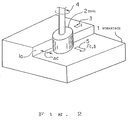
- Figure 2 is a diagram showing the relationship between a tool and a workpiece.
- a tool 2 machines the machining surface 1a of a workpiece 1, wherein the tool 2 travels in the direction shown by the arrow 3 and rotates in the direction shown by the arrow 4. At this time, the tool 2 is deformed by a deformation amount ⁇ , due to the action thereon of a cutting reaction force Fc, in the direction shown by the arrow 5.
- This deformation amount ⁇ is determined by tool deformation parameters and machining conditions.
- the tool deformation parameters include the rigidity Ts of the tool 2 and the hardness Wh of the workpiece 1 and the like, and the machining conditions include a cutting depth ⁇ c, cutting speed f, rpm of a spindle S, and directions of rotation of the spindle Sd (up-cutting) or down-cutting) and the like.
- a tool deformation amount is calculated based on these tool deformation parameters and machining conditions and the tool deformation amount can be corrected, thereby obtain a more accurate machining, by adding the thus determined tool deformation amount to a movement command in the same way as a tool correction amount.
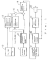
- Figure 1 is a block diagram of a tool deformation amount correction system according to the present invention, where in a preprocessing arithmetic operation means 12 reads a machining program 11 and supplies the machining conditions including the cutting depth ⁇ c, cutting speed f, rpm of a spindle S, and direction of rotation of the spindle Sd and the like to a tool deformation amount calculation means 13, which reads the tool deformation parameters including the rigidity Ts of the tool 2 and the hardness Wh of the workpiece 1 and the like, from a memory 15.
- a preprocessing arithmetic operation means 12 reads a machining program 11 and supplies the machining conditions including the cutting depth ⁇ c, cutting speed f, rpm of a spindle S, and direction of rotation of the spindle Sd and the like to a tool deformation amount calculation means 13, which reads the tool deformation parameters including the rigidity Ts of the tool 2 and the hardness Wh of the workpiece 1 and the like, from a memory 15.
- the tool deformation amount calculation means 13 calculates the tool deformation amount from these tool deformation parameters and machining conditions.
- a calculation formula for determining the tool deformation amount is predetermined by experiments and the like. Further, the calculation formula also can be arranged as a data table in accordance with materials and workpieces.
- a tool correction means 14 reads an offset amount R from the memory 15 and determines an offset vector.
- the tool deformation amount is generally determined as the amount of change of the directions of the offset vector, and as a result, when the offset vector and tool deformation amount are added by an adder 16, an offset vector including the tool deformation amount can be determined.
- This offset vector is added to a movement command from the preprocessing arithmetic operation means 12, by the adder 17, and supplied to an interpolation means 18, which interpolates this value and outputs an interpolation pulse.
- the output interpolation pulse is accelerated or decelerated by a speed acceleration/deceleration means 19 and supplied to a position control circuit 20, which converts the interpolation pulse to a speed command signal and supplies same to a servo amplifier 21, which amplifies this speed command signal to thereby drive a servo motor 22.
- the servo motor 22 contains a pulse coder by which a position feedback pulse is fed back to the position control circuit 20.
- the tool deformation amount is calculated as a component in the same direction as that of the offset vector
- the tool deformation amount may be determined as an independent tool deformation vector and added to the offset vector.
- the present invention can be applied in the same way to a cutting tool used in a lathe.
- the tool correction means determines a tool length as a correction amount
- the tool deformation amount is determined as a Z-axis component and Y-axis component (vertical component).
- the Z-axis component can be corrected in the same way as a usual tool length correction, but the Y-axis component must be corrected by being converted into an X-axis component.
- a tool deformation amount is calculated from tool deformation parameters and machining conditions, and then corrected, a machining can be accurately carried out, and thus a trial cutting becomes unnecessary, and accordingly, the machining time can be shortened.
Landscapes
- Engineering & Computer Science (AREA)
- Human Computer Interaction (AREA)
- Manufacturing & Machinery (AREA)
- Physics & Mathematics (AREA)
- General Physics & Mathematics (AREA)
- Automation & Control Theory (AREA)
- Numerical Control (AREA)
Abstract
Claims (7)
- Un système pour corriger une grandeur de déformation d'un outil par lequel la grandeur de déformation d'un outil (2) est corrigée en vue d'un usinage, comprenant :
une mémoire (15) pour stocker des paramètres de déformation d'outil afin de calculer une grandeur de déformation d'outil ;
des moyens de correction d'outil (14) pour calculer une grandeur de correction d'outil ;
un additionneur (17) pour ajouter ladite grandeur de correction d'outil à un ordre de déplacement et pour déterminer une grandeur de déplacement ; et
des moyens d'interpolation (18) pour interpoler ladite grandeur de déplacement ; caractérisé par :
des moyens à fonctionnement arithmétique de prétraitement (12) pour lire un programme d'usinage et délivrer des conditions d'usinage ;
des moyens de calcul de grandeur de déformation d'outil (13) pour déterminer la grandeur de déformation d'outil à partir desdits paramètres de déformation d'outil et desdites conditions d'usinage ; et
l'additionneur (17) ajoutant également la grandeur de déformation d'outil à l'ordre de déplacement. - Un système pour corriger une grandeur de déformation d'un outil selon la revendication 1, dans lequel lesdits paramètres de déformation d'outil comprennent au moins un parmi une rigidité d'un outil (2) et une dureté d'une pièce d'ouvrage (1).
- Un système pour corriger une grandeur de déformation d'un outil selon la revendication 1, dans lequel lesdites conditions d'usinage comprennent au moins un parmi une profondeur de découpe, une vitesse de découpe, un tpm d'une broche (5) et un sens de rotation de la broche.
- Un système pour corriger une grandeur de déformation d'un outil selon la revendication 1, dans lequel ledit outil (2) est un outil de fraisage et lesdits moyens de correction d'outil (14) sont des moyens de correction du trajet de l'outil.
- Un système pour corriger une grandeur de déformation d'un outil selon la revendication 4, dans lequel ladite grandeur de déformation d'outil est déterminée en tant que grandeur de variation d'une direction d'un vecteur décalé.
- Un système pour corriger une grandeur de déformation d'un outil selon la revendication 1, dans lequel ledit outil (2) est un outil de découpe et lesdits moyens de correction d'outil (14) sont des moyens de correction de la longueur de l'outil.
- Un système pour corriger une grandeur de déformation d'un outil selon la revendication 6, dans lequel une composante de déformation d'axe Y de ladite grandeur de déformation d'outil est convertie en une composante d'axe X.
Applications Claiming Priority (3)
| Application Number | Priority Date | Filing Date | Title |
|---|---|---|---|
| JP162087/90 | 1990-06-20 | ||
| JP2162087A JPH0452908A (ja) | 1990-06-20 | 1990-06-20 | 工具変形量補正方式 |
| PCT/JP1991/000753 WO1991019592A1 (fr) | 1990-06-20 | 1991-06-04 | Systeme pour corriger une grandeur de deformation d'un outil |
Publications (3)
| Publication Number | Publication Date |
|---|---|
| EP0487738A1 EP0487738A1 (fr) | 1992-06-03 |
| EP0487738A4 EP0487738A4 (en) | 1992-08-19 |
| EP0487738B1 true EP0487738B1 (fr) | 1996-01-03 |
Family
ID=15747838
Family Applications (1)
| Application Number | Title | Priority Date | Filing Date |
|---|---|---|---|
| EP91910154A Expired - Lifetime EP0487738B1 (fr) | 1990-06-20 | 1991-06-04 | Systeme pour corriger une grandeur de deformation d'un outil |
Country Status (5)
| Country | Link |
|---|---|
| US (1) | US5479353A (fr) |
| EP (1) | EP0487738B1 (fr) |
| JP (1) | JPH0452908A (fr) |
| DE (1) | DE69116112T2 (fr) |
| WO (1) | WO1991019592A1 (fr) |
Families Citing this family (12)
| Publication number | Priority date | Publication date | Assignee | Title |
|---|---|---|---|---|
| JPH087614B2 (ja) * | 1992-03-27 | 1996-01-29 | 株式会社牧野フライス製作所 | 工作機械の工具長補正方法及び装置 |
| US5621294A (en) * | 1995-11-21 | 1997-04-15 | Universal Instruments Corporation | Apparatus and method for force compensation in a variable reluctance motor |
| AU762544B2 (en) * | 1997-06-30 | 2003-06-26 | Fuji Photo Film Co., Ltd. | Image communication system and method |
| US6582166B1 (en) | 1999-10-22 | 2003-06-24 | Gerber Scientific Products, Inc. | Method of compensating for cutter deflection |
| CA2427702A1 (fr) * | 2000-11-03 | 2002-05-10 | Synthes (U.S.A.) | Determination de deformations d'instruments chirurgicaux |
| JP4778631B2 (ja) * | 2001-05-15 | 2011-09-21 | 富士重工業株式会社 | 試験模型の移動シミュレーション試験方法及びその装置 |
| US20030163147A1 (en) * | 2002-02-22 | 2003-08-28 | Rabiner Robert A. | Apparatus and method for using a vascular introducer with an ultrasonic probe |
| WO2008011845A1 (fr) * | 2006-07-28 | 2008-01-31 | Siemens Aktiengesellschaft | Compensation de la compliance dépendant de la position pour une machine-outil |
| JP5465922B2 (ja) * | 2009-05-15 | 2014-04-09 | Dmg森精機株式会社 | 加工方法及び加工システム |
| JP6011353B2 (ja) * | 2013-01-17 | 2016-10-19 | 日立金属株式会社 | 加工条件予測装置および加工条件予測方法 |
| JP7112375B2 (ja) | 2019-07-24 | 2022-08-03 | 株式会社日立製作所 | Ncプログラム生成システム及びncプログラム生成方法 |
| JP7517814B2 (ja) * | 2019-12-04 | 2024-07-17 | ファナック株式会社 | 数値制御装置、及び制御方法 |
Family Cites Families (13)
| Publication number | Priority date | Publication date | Assignee | Title |
|---|---|---|---|---|
| AU461290B2 (en) * | 1970-12-29 | 1975-05-22 | Toshiba Machine Co. Ltd. | Method and apparatus for in-feed control for improving the accuracy of machining of a workpiece |
| US4031368A (en) * | 1972-04-17 | 1977-06-21 | Verkstadsteknik Ab | Adaptive control of cutting machining operations |
| US4078195A (en) * | 1976-01-13 | 1978-03-07 | Macotech Corporation | Adaptive control system for numerically controlled machine tools |
| JPS5341872A (en) * | 1976-09-29 | 1978-04-15 | Okuma Mach Works Ltd | System for automatically controlling serviceable life of tools |
| IT1165014B (it) * | 1979-03-27 | 1987-04-22 | Innocenti Santeustacchio Spa | Sistema di controllo geometrico,per aumentare la precisione du una macchina utensile,particolarmente di una macchina utensile di grandi dimensioni |
| JPS57138562A (en) * | 1981-02-20 | 1982-08-26 | Okuma Mach Works Ltd | Correction device for tool |
| US4620281A (en) * | 1981-09-22 | 1986-10-28 | General Electric Company | In-process cutting tool condition compensation and part inspection |
| JPS5981705A (ja) * | 1982-11-02 | 1984-05-11 | Fanuc Ltd | Nc工作機械における補正方法 |
| JPS59212909A (ja) * | 1983-05-17 | 1984-12-01 | Toyoda Mach Works Ltd | 工具寸法補正制御装置 |
| JPS6179549A (ja) * | 1984-09-28 | 1986-04-23 | Takaaki Nagao | 曲面加工装置 |
| JPS62213945A (ja) * | 1986-03-12 | 1987-09-19 | Toshiba Mach Co Ltd | 工作機械の熱変位補正装置 |
| JPS63272447A (ja) * | 1987-04-30 | 1988-11-09 | Mitsubishi Heavy Ind Ltd | たわみ量補正付送り制御装置 |
| US5025592A (en) * | 1988-05-09 | 1991-06-25 | Brother Kogyo Kabushiki Kaisha | Machine tool having workpiece machining dimension and tool length measuring functions |
-
1990
- 1990-06-20 JP JP2162087A patent/JPH0452908A/ja active Pending
-
1991
- 1991-06-04 DE DE69116112T patent/DE69116112T2/de not_active Expired - Fee Related
- 1991-06-04 EP EP91910154A patent/EP0487738B1/fr not_active Expired - Lifetime
- 1991-06-04 WO PCT/JP1991/000753 patent/WO1991019592A1/fr not_active Ceased
- 1991-06-04 US US07/828,971 patent/US5479353A/en not_active Expired - Fee Related
Also Published As
| Publication number | Publication date |
|---|---|
| WO1991019592A1 (fr) | 1991-12-26 |
| DE69116112T2 (de) | 1996-05-15 |
| US5479353A (en) | 1995-12-26 |
| EP0487738A1 (fr) | 1992-06-03 |
| DE69116112D1 (de) | 1996-02-15 |
| EP0487738A4 (en) | 1992-08-19 |
| JPH0452908A (ja) | 1992-02-20 |
Similar Documents
| Publication | Publication Date | Title |
|---|---|---|
| US6097168A (en) | Position control apparatus and method of the same, numerical control program preparation apparatus and method of the same, and methods of controlling numerical control machine tool | |
| US5404308A (en) | Numerical control (NC) device to control feed speed of tool based on speed of spindle and amount of change of spindle speed | |
| KR100354878B1 (ko) | 절삭 공구에 의한 오비트 가공용 서보 제어 방법 및 오비트 가공용 서보 제어 장치 | |
| EP0487738B1 (fr) | Systeme pour corriger une grandeur de deformation d'un outil | |
| EP0268887B1 (fr) | Commande numérique d'avancement pour une machine-outil | |
| EP0098309B1 (fr) | Systeme d'usinage a commande numerique | |
| GB1395683A (en) | Closed loop control system | |
| JPH0736514A (ja) | 3次元工具径補正方式 | |
| WO2008053601A1 (fr) | Dispositif de contrôle de travail et son programme | |
| JP2003005815A (ja) | 数値制御工作機械の送り速度・加速度制御方法および数値制御装置 | |
| CA1334864C (fr) | Methode et dispositif de commande pour machines-outils telles un tour | |
| EP0453571A1 (fr) | Procede de correction des fluctuations de position d'une machine | |
| JP5334932B2 (ja) | パラメータ設定方法およびパラメータ設定装置 | |
| JPH04323705A (ja) | 回転軸同期繰り返し制御方法及び装置 | |
| JP3445474B2 (ja) | 位置制御装置および位置制御方法 | |
| JP4982170B2 (ja) | 加工制御装置および加工制御プログラム | |
| JP2800124B2 (ja) | 数値制御工作機械の制御方法及びそのための制御装置 | |
| JP3454616B2 (ja) | Nc工作機械の送り軸制御方法および装置 | |
| JP4036502B2 (ja) | Ncプログラム作成方法、作成装置及びnc工作機械の制御方法 | |
| JP2926524B2 (ja) | 試切削機能を有する数値制御装置 | |
| JPS6239160A (ja) | 数値制御装置付き工作機械 | |
| JPS6299020A (ja) | ねじ切り制御方式 | |
| JPH044405A (ja) | 数値制御装置 | |
| JPS62176739A (ja) | 工作機械の真直度補正装置 | |
| JP2579911B2 (ja) | 倣い動作による高速nc加工装置 |
Legal Events
| Date | Code | Title | Description |
|---|---|---|---|
| PUAI | Public reference made under article 153(3) epc to a published international application that has entered the european phase |
Free format text: ORIGINAL CODE: 0009012 |
|
| 17P | Request for examination filed |
Effective date: 19920311 |
|
| AK | Designated contracting states |
Kind code of ref document: A1 Designated state(s): DE FR IT |
|
| A4 | Supplementary search report drawn up and despatched |
Effective date: 19920702 |
|
| AK | Designated contracting states |
Kind code of ref document: A4 Designated state(s): DE FR IT |
|
| 17Q | First examination report despatched |
Effective date: 19940629 |
|
| GRAA | (expected) grant |
Free format text: ORIGINAL CODE: 0009210 |
|
| AK | Designated contracting states |
Kind code of ref document: B1 Designated state(s): DE FR IT |
|
| PG25 | Lapsed in a contracting state [announced via postgrant information from national office to epo] |
Ref country code: FR Effective date: 19960103 |
|
| REF | Corresponds to: |
Ref document number: 69116112 Country of ref document: DE Date of ref document: 19960215 |
|
| ITF | It: translation for a ep patent filed | ||
| EN | Fr: translation not filed | ||
| PGFP | Annual fee paid to national office [announced via postgrant information from national office to epo] |
Ref country code: DE Payment date: 19960612 Year of fee payment: 6 |
|
| PLBE | No opposition filed within time limit |
Free format text: ORIGINAL CODE: 0009261 |
|
| STAA | Information on the status of an ep patent application or granted ep patent |
Free format text: STATUS: NO OPPOSITION FILED WITHIN TIME LIMIT |
|
| 26N | No opposition filed | ||
| PG25 | Lapsed in a contracting state [announced via postgrant information from national office to epo] |
Ref country code: DE Free format text: LAPSE BECAUSE OF NON-PAYMENT OF DUE FEES Effective date: 19980303 |
|
| PG25 | Lapsed in a contracting state [announced via postgrant information from national office to epo] |
Ref country code: IT Free format text: LAPSE BECAUSE OF NON-PAYMENT OF DUE FEES Effective date: 20050604 |