EP0487772B1 - Procédé et dispositif de traitement de viande - Google Patents
Procédé et dispositif de traitement de viande Download PDFInfo
- Publication number
- EP0487772B1 EP0487772B1 EP90122740A EP90122740A EP0487772B1 EP 0487772 B1 EP0487772 B1 EP 0487772B1 EP 90122740 A EP90122740 A EP 90122740A EP 90122740 A EP90122740 A EP 90122740A EP 0487772 B1 EP0487772 B1 EP 0487772B1
- Authority
- EP
- European Patent Office
- Prior art keywords
- meat
- separation
- stage
- drum
- disintegrating
- Prior art date
- Legal status (The legal status is an assumption and is not a legal conclusion. Google has not performed a legal analysis and makes no representation as to the accuracy of the status listed.)
- Expired - Lifetime
Links
- 235000013372 meat Nutrition 0.000 title claims description 68
- 238000000034 method Methods 0.000 title claims description 42
- 238000012545 processing Methods 0.000 title description 4
- 238000000926 separation method Methods 0.000 claims description 63
- 238000005520 cutting process Methods 0.000 claims description 26
- 230000008569 process Effects 0.000 claims description 14
- 238000005188 flotation Methods 0.000 claims description 3
- 230000007704 transition Effects 0.000 claims description 3
- 230000005484 gravity Effects 0.000 claims description 2
- 238000003801 milling Methods 0.000 claims description 2
- 230000000712 assembly Effects 0.000 claims 1
- 238000000429 assembly Methods 0.000 claims 1
- 230000007423 decrease Effects 0.000 claims 1
- 239000012858 resilient material Substances 0.000 claims 1
- 230000000007 visual effect Effects 0.000 claims 1
- 210000003205 muscle Anatomy 0.000 description 18
- 210000002808 connective tissue Anatomy 0.000 description 13
- 210000000988 bone and bone Anatomy 0.000 description 12
- 210000000845 cartilage Anatomy 0.000 description 9
- 238000013461 design Methods 0.000 description 9
- 238000010586 diagram Methods 0.000 description 7
- 210000003041 ligament Anatomy 0.000 description 6
- 230000029087 digestion Effects 0.000 description 5
- 238000004537 pulping Methods 0.000 description 5
- 238000011144 upstream manufacturing Methods 0.000 description 5
- 238000002474 experimental method Methods 0.000 description 4
- 210000002435 tendon Anatomy 0.000 description 4
- 238000011161 development Methods 0.000 description 3
- 210000003195 fascia Anatomy 0.000 description 3
- 239000000463 material Substances 0.000 description 3
- 230000002093 peripheral effect Effects 0.000 description 3
- 238000003825 pressing Methods 0.000 description 3
- 210000001519 tissue Anatomy 0.000 description 3
- 238000010521 absorption reaction Methods 0.000 description 2
- 230000015572 biosynthetic process Effects 0.000 description 2
- 235000013622 meat product Nutrition 0.000 description 2
- 239000003755 preservative agent Substances 0.000 description 2
- 238000007790 scraping Methods 0.000 description 2
- 238000012216 screening Methods 0.000 description 2
- 238000012360 testing method Methods 0.000 description 2
- 239000004278 EU approved seasoning Substances 0.000 description 1
- 206010035148 Plague Diseases 0.000 description 1
- 241000607479 Yersinia pestis Species 0.000 description 1
- 239000002253 acid Substances 0.000 description 1
- 150000007513 acids Chemical class 0.000 description 1
- 230000009471 action Effects 0.000 description 1
- 230000006978 adaptation Effects 0.000 description 1
- 210000000577 adipose tissue Anatomy 0.000 description 1
- CUZMQPZYCDIHQL-VCTVXEGHSA-L calcium;(2s)-1-[(2s)-3-[(2r)-2-(cyclohexanecarbonylamino)propanoyl]sulfanyl-2-methylpropanoyl]pyrrolidine-2-carboxylate Chemical compound [Ca+2].N([C@H](C)C(=O)SC[C@@H](C)C(=O)N1[C@@H](CCC1)C([O-])=O)C(=O)C1CCCCC1.N([C@H](C)C(=O)SC[C@@H](C)C(=O)N1[C@@H](CCC1)C([O-])=O)C(=O)C1CCCCC1 CUZMQPZYCDIHQL-VCTVXEGHSA-L 0.000 description 1
- 239000000470 constituent Substances 0.000 description 1
- 238000010276 construction Methods 0.000 description 1
- 230000003247 decreasing effect Effects 0.000 description 1
- 239000013013 elastic material Substances 0.000 description 1
- 210000003608 fece Anatomy 0.000 description 1
- 235000011194 food seasoning agent Nutrition 0.000 description 1
- 239000007788 liquid Substances 0.000 description 1
- 230000003287 optical effect Effects 0.000 description 1
- 238000002360 preparation method Methods 0.000 description 1
- 230000009467 reduction Effects 0.000 description 1
- 150000003839 salts Chemical class 0.000 description 1
- 239000007787 solid Substances 0.000 description 1
- 238000012549 training Methods 0.000 description 1
- XLYOFNOQVPJJNP-UHFFFAOYSA-N water Substances O XLYOFNOQVPJJNP-UHFFFAOYSA-N 0.000 description 1
Images
Classifications
-
- A—HUMAN NECESSITIES
- A22—BUTCHERING; MEAT TREATMENT; PROCESSING POULTRY OR FISH
- A22C—PROCESSING MEAT, POULTRY, OR FISH
- A22C17/00—Other devices for processing meat or bones
- A22C17/0006—Cutting or shaping meat
- A22C17/0026—Mincing and grinding meat
-
- A—HUMAN NECESSITIES
- A22—BUTCHERING; MEAT TREATMENT; PROCESSING POULTRY OR FISH
- A22C—PROCESSING MEAT, POULTRY, OR FISH
- A22C17/00—Other devices for processing meat or bones
- A22C17/0006—Cutting or shaping meat
- A22C17/002—Producing portions of meat with predetermined characteristics, e.g. weight or particular dimensions
-
- A—HUMAN NECESSITIES
- A22—BUTCHERING; MEAT TREATMENT; PROCESSING POULTRY OR FISH
- A22C—PROCESSING MEAT, POULTRY, OR FISH
- A22C17/00—Other devices for processing meat or bones
- A22C17/04—Bone cleaning devices
Definitions
- the present invention relates to a method and an apparatus for processing meat, as known from document DE-A-1507972, the meat being comminuted in a first step and subjected to a one- or multi-stage separation process in a subsequent further step.
- This preparation consists in separating the actual muscle tissue from bones, ligaments, cartilages, fascia, connective tissue, fat and the like.
- the "pure" muscle tissue obtained in this way can then be processed further to the desired meat product, while the separated components are processed, processed or disposed of in separate work steps for other purposes.
- the separation of the muscle tissue from the above-mentioned components causes considerable problems in practice.
- the solid components such as the bones or cartilage, can still be separated relatively easily and completely from the soft components, such as the muscle tissue and the fat.
- relatively soft components such as fat, soft connective tissue or similar components are to be separated from soft muscle tissue. Even using modern procedures and devices, only a relatively unsatisfactory degree of separation can be achieved.
- a common, known procedure consists, for example, in a first step of comminuting the meat, including bones or bone parts and other components, in a type of meat grinder, and passing the comminuted product in this way between a press belt and a sieve drum (see, for example, DE -OS 38 44 301 or DE-AS 17 82 800).
- the comminution in the meat grinder creates a mixed meat mass, the soft components of which are then squeezed through the perforation of the drum in a kind of passing process over the press belt.
- components of softer and harder consistency can be separated. Separating soft components from one another, such as, for example, separating them into muscle tissue, soft connective tissue and fat, is not possible or is possible only inadequately with this procedure.
- the muscle tissue is also caused in the upstream comminution step and in particular in the subsequent separation step the squeezing processes, high pressures, shear forces and other mechanical loads, which largely destroy the structure of the muscle tissue, so that no high-quality result can be achieved.
- This object is achieved in that the chopping takes place in the first step by dividing the meat into flat pieces of a certain thickness, and in a second step between the first step and the single-stage or multi-stage separation process, a disintegration tailored to this separation process flat pieces is made so that their structure is deliberately broken.
- Mechanical disintegration has long been known in meat processing.
- Mechanical "unlocking” is understood to mean a mechanical action on the meat which specifically breaks up the structure of the meat. In this way it is possible, for example, to improve the absorption of preservatives and / or seasonings (feces) or to increase the "tenderness" of the meat due to the reduction in strength.
- the meat is carefully divided into flat pieces, such as slices, strips or cutlets.
- the material present in flat pieces is then mechanically disrupted prior to the actual separation process in such a way that the “disintegration pattern” is precisely matched to the “pattern” used in the subsequent separation process.
- the separation process is carried out using a sieve drum or sieve belt arrangement, the incision, notch or puncture pattern of the mechanical unlocking process is precisely matched to the perforation pattern of the sieve drum or sieve belt arrangement.
- the incisions or punctures of the mechanical unlocking process are placed in such a way that a cutting grid is created, by means of which each meat section lying within the cuts can be gently squeezed out in the subsequent cutting process.
- the type and consistency of the meat play an important role. For example, in the case of a separation process using a press belt sieve drum arrangement with the same cutting pattern and the same pressure, tender meat can be pressed out via a smaller perforation than less tender or tough meat, for which a larger perforation is required in any case.
- Another parameter is the pressing pressure applied to the material to be processed in each stage. Tests have shown that it is advantageous to increase the pressing pressure from stage to stage.
- the mechanical disintegration makes it possible not to exert a large area pressure on the meat over a longer period of time, but rather to exert a smaller area pressure over a shorter period. If rolls or press belt sieve drum arrangements are used, it is also advantageous not to work with a so-called zero gap, but with a certain distance between the pressure-exerting surfaces. If a press belt is used, this can be achieved with a low press belt tension.
- the degree of separation can be improved by using an intermediate stage between two stages. So it is possible, for example, to use a flotation stage as an intermediate stage, in which a separation by flotation in water or in food-approved solutions of salts and / or edible acids takes place.
- an intermediate stage for fine separation can also be used, if appropriate, for adhesion separation processes, vibrating table separation processes, centrifugal separation processes or, if appropriate, also air separation processes using the different specific weights of fat and muscle tissue.
- An advantageous device for carrying out the method according to the invention comprises a cutting device for dividing the meat into flat pieces of a certain thickness, a mechanical disintegrating device which adjoins the structure of the flat pieces in a targeted manner and a single or multi-stage separating device which adjoins this and is matched to this .
- the cutting device, the disintegrating device and the separating device can be separated from one another.
- the cutting device, the disintegrating device and the separating device are combined in series to form a machine unit.
- the cutting device can be constructed in various ways. It is essential that the meat can be divided into flat pieces of predetermined thickness with the least possible care. It is advantageous to provide a screw conveyor with a rotating knife connected upstream on the output side as the cutting device. Depending on the application, this rotating knife can be preceded by a so-called gate knife.
- the rotating knife can be designed as a wing or disc knife.
- the drive can take place through the shaft of the screw conveyor, which in such a case is designed as a hollow shaft.
- the cutting device can also be designed as a disk knife arrangement guided on a horizontal axis and working together with a conveyor belt.
- the cutting device as Frozen meat block cutter is trained.
- a frozen meat block cutter can work, for example, as a sawing or milling device.
- the mechanical unlocking device can also be designed in a wide variety of ways. It is advantageous if the mechanical disintegration device has disintegration rollers which are opposite one another and rotate in opposite directions to one another.
- the flat pieces of meat can be moved through between the digestion rollers in a variety of ways. In most cases it is sufficient to take care of a supply and removal, since the flat pieces of meat are conveyed through the pulping rollers themselves through the pulping device. If this should not be the case, it is advantageous to provide a special transport device. In the event that the axes of the pulping rollers lie in a horizontal plane, gravity is generally sufficient to move the flat pieces of meat into the feed area of the pulping rollers.
- the unlocking rollers consist of drive shafts on which a number of toothed disks are located axially next to one another are arranged. With such an arrangement, it is advantageous to arrange the drive shafts next to one another with adjustable spacing in order to be able to determine the optimum working gap between the digestion rollers by experiments. Due to the formation of the disintegrating rollers from a number of toothed disks, it is possible to assemble sets of toothed disks from different toothed disks according to the respective application.
- Digestion rollers composed of toothed disks can also be easily cleaned.
- the toothed lock washers are removed from the drive shafts and cleaned individually in a separate operation.
- toothed disks have puncture or incision teeth on their circumference, which are shaped according to a predetermined unlocking pattern and arranged with respect to one another.
- the separating device can also be designed in a wide variety of ways. It can be of one or more stages, the stages being of the same or different design.
- a particularly good relationship between the degree of separation and the expenditure on equipment results from a two- or three-stage design of the separating device.
- the individual stages of the separating device can be designed as a press belt sieve drum unit, sieve belt press drum unit, sieve drum sieve drum unit or sieve drum pressure roller unit.
- the interior runs the printing or screening drum has a rotating screen or printing drum with a smaller diameter. Due to the offset of the two axes, a working gap is formed between the inner surface of the outer drum and the outer surface of the inner drum, which gap is continuously reduced and subsequently expanded again.
- the screen drum is opposed to a pressure roller parallel to the axis.
- This pressure roller can consist of elastic material or can also be designed to be elastically deformable.
- the pressure roller In the case of an elastic, deformable design of the pressure roller, it is advantageous to design it as a hollow pressure body which can be acted upon by a pressure medium on its inside. With such a configuration, the printing roller undergoes a deformation in its printing area opposite the screen drum, which deformation can extend over a certain angular range of the screen drum in accordance with the desired printing area. An angular range of approximately 30 ° to 50 ° is advantageous.
- the meat pressed into the interior of the sieve drum can in principle be removed in any manner.
- Known scraping and discharge devices are suitable for this purpose, for example.
- the meat can also be removed from the inside of the sieve drum by means of a suction device which is arranged in the interior of the drum in the region of the overlap by the pressure rollers.
- This suction device can be designed in various ways. The training as a suction hood, which covers a certain sector of the interior, is advantageous.
- the separating device can also be designed as a toothed drum arrangement.
- two toothed drums lie opposite each other parallel to the formation of a pair of toothed drums.
- the toothing of the toothed drums can be straight, helical or even arrow-toothed, depending on the application.
- the toothing of the toothed drums can be designed in different ways.
- the teeth can thus be formed in one piece with the toothed drum. It is also advantageous to form the teeth of the toothed drums of toothed racks which are placed on the drum body.
- toothed drum arrangements ultimately constitute a sieve drum arrangement with special, i.e. tooth-like circumferential surface.
- the openings or slots can be designed in a wide variety of ways. In order to ensure that the meat passes through the openings or slots as smoothly as possible, it is advantageous to design the openings or slots to be extended toward the interior of the drum. It is advisable to make the extension essentially conical.
- this transition can be rounded, for example, or it can be designed like a cutting edge.
- toothed drum arrangement it is expedient to arrange the toothed drums at a distance from one another, i.e. to form a "wavy" working gap between the facing tooth systems.
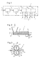
- the meat which still has all the constituents, such as muscle tissue, bones, ligaments, cartilage, fascia, connective tissue, fat and the like, is obtained via meat with an arrow 5 schematically marked transport device fed into the cutting device 2.
- the meat, including its components is divided into flat pieces. These flat pieces are fed to the unlocking device 3 via a conveyor device schematically indicated by an arrow 6, in which they are mechanically unlocked according to a precisely specified pattern.
- the separating device 4 consists of two or three stages, as is shown in the block diagram according to FIG. 1 with dashed lines.
- the second and third stages are identified in the block diagram according to FIG. 1 with 4b and 4c.
- stages 4a, 4b and 4c the separation process described in the introduction takes place, which can be carried out according to the invention with a very high degree of separation due to the upstream and precisely coordinated mechanical unlocking process in the unlocking device 3.
- the main amount of muscle tissue is already separated in the first stage 4a of the separating device 4, which is symbolized by an arrow 8 in the block diagram according to FIG.
- the second stage 4b When moving to the second stage 4b, only residual muscle tissue, soft connective tissue, fatty tissue, tendons, fasciae, ligaments, cartilage and bone remain.
- the degree of separation can, if necessary, be improved further by using intermediate stages in accordance with an advantageous development of the invention.
- These intermediate stages are not shown in FIG. 1. As already described, they are used for fine separation.
- the components separated in these intermediate stages are indicated schematically in the block diagram according to FIG. 1 with the arrows 12a and 12b.
- the exemplary embodiment of a cutting device 2 shown in FIG. 2 consists of a screw conveyor 13 which, through a drive shaft 14 and a drive 15, gently presses the meat fed in via a funnel 16 through a gate knife 17 on the discharge side.
- Gate knives are known in principle and produce pieces of meat with a precise geometric dimension, which are then cut to a desired length by a downstream rotating knife 18.
- the meat is divided into flat pieces of defined thickness in the cutting device 2.
- FIG. 3 schematically shows an exemplary embodiment of a disintegrating device 3 in which the flat pieces of a certain thickness are mechanically disintegrated in accordance with a precisely specified pattern.
- the unlocking device 3 comprises a transport device 19, which is shown in a channel-like manner for the sake of simplicity.
- Toothed disks 22 are arranged axially next to one another on the drive shafts 20, so that opening rollers 23 are formed which act on the flat pieces of a certain thickness from both sides.
- the toothed disks 22 are equipped in their circumferential area with puncturing or incision teeth 24 which are shaped in accordance with the unlocking pattern already mentioned and are arranged with respect to one another.
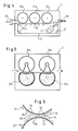
- the separating device 4 shown schematically in FIG. 4 is a three-stage sieve drum press belt arrangement.
- three sieve drums 25a, 25b and 25c are arranged at a certain distance one behind the other with axes parallel to one another.
- a press belt 26 is guided over rollers 27 in such a way that the flat pieces of meat mechanically disrupted in the opening device 3 are passed one after the other first under the sieve drum 25a and then under the sieve drums 25b and 25c.
- the working direction of the separating device shown in FIG. 4 is indicated by arrows 28.
- the press belt 26 is driven by a drive 29 or a plurality of drive press rolls. The drive of the sieve drums is not shown.
- the size of the perforation of the sieve drums, the length of the press nip between the press belt 26 and the associated sieve drum surface, the height of the press nip and the pressure on the flat pieces of meat are determined and set according to the respective requirements by tests for the respective type and consistency of meat in a known manner. While the harder meat components leave the separating device 4 on the output side via the press belt 26, the softer meat components are removed from the interior of the sieve drums in a manner known per se by scraping or conveying devices, not shown.
- Screen drums 30a and 30b are also used in the two-stage separating device 4 shown schematically in FIG. Instead of a press belt, the screen drums 30a and 30b are opposed by pressure rollers 31a and 31b, which are made of an elastically deformable material, such as special rubber or plastic, and are designed as a hollow pressure body. Devices, not shown, act on the inside of the hollow pressure body with a pressure medium, such as air or liquid.
- a pressure medium such as air or liquid.
- the arrangement is such that the pressure rollers 31a and 31b enclose the screening drums 30a and 30b over a certain angle of their circumference.
- the angle is chosen according to the meat to be processed and the dimensions of the flat pieces and is preferably between 30 ° and 50 °.
- the pressure in turn can be controlled via the pressure of the pressure medium.
- the embodiment variant according to FIG. 5 works in the same way as the embodiment according to FIG. 4.
- FIG. 1 A detail of a further embodiment is shown in FIG.
- the working gap through which the flat meat pieces of a certain thickness are mechanically disrupted in the opening device 3 is formed by the gap between two toothed drums 32, of which only a part of the circumference is shown schematically.
- These toothed drums 32 have rounded teeth 33 in the area of their circumference. These teeth have rounded tooth tips 34.
- a tooth base 35 which is designed in accordance with the shape of the opposite tooth tips 34 is provided and has openings or slots 36 through which a connection from the Toothed drum peripheral surface is made to the interior.
- the toothed drums 32 are thus sieve drums with a toothed peripheral surface.
- the toothed drums 32 of each pair of toothed drums are arranged at a distance from one another to form the working gap, as can be seen from FIG. They are driven synchronously, in such a way that the tooth tip 34 of a toothed drum is opposite the tooth base 35 of the adjacent toothed drum.
- a “wave-shaped” working gap is formed, as can be clearly seen from FIG. 6.
- the soft components of the meat are pressed out into the interior of the toothed drums via the openings or slots 36 and then withdrawn from them in a known manner.
- the peculiarity of this arrangement is that the squeezing process takes place alternately, and thus pulsates to one side and the other, while the meat is moved through the undulating working gap. Such an arrangement results in a particularly good degree of separation with gentle treatment.
Landscapes
- Life Sciences & Earth Sciences (AREA)
- Engineering & Computer Science (AREA)
- Wood Science & Technology (AREA)
- Zoology (AREA)
- Food Science & Technology (AREA)
- Meat, Egg Or Seafood Products (AREA)
- Processing Of Meat And Fish (AREA)
- Crushing And Pulverization Processes (AREA)
Claims (49)
- Procédé de traitement de viande, la viande étant, dans une première étape, fractionnée et, dans une autre étape, subséquente, soumise à un processus de séparation, lui-même effectué en une ou plusieurs étapes caractérisé en ce que,- le fractionnement s'effectue à la première étape par subdivision de la viande en morceaux plats d'épaisseur déterminée,- et en ce que, dans une deuxième étape, située entre la première étape et l'autre étape subséquente, est effectuée une préparation mécanique, adaptée au processus de séparation, des morceaux plats, de sorte que leur structure soit cassée, à dessein.
- Procédé selon la revendication 1, caractérisé en ce que le processus de séparation subséquent au processus de préparation mécanique s'effectue en deux ou trois étapes.
- Procédé selon la revendication 2, caractérisé en ce que la pression, appliquée sur la viande pendant le processus de séparation, est augmentée d'une étape à l'autre.
- Procédé selon la revendication 2, caractérisé en ce qu'une pression spécifique comparativement élevée agit sur la viande pendant un intervalle de temps relativement court.
- Procédé selon la revendication 3, caractérisé en ce que la pression est exercée sur la viande par des surfaces, dont l'espacement est réglable et va en diminuant d'une étape à l'autre.
- Procédé selon la revendication 1 ou 2, caractérisé en ce que, pour effectuer la séparation fine, au moins une étape intermédiaire est prévue entre le processus de préparation mécanique et le processus de séparation subséquent.
- Procédé selon la revendication 2, caractérisé en ce qu'au moins un étage intermédiaire est prévu entre les deux étapes pour effectuer la séparation fine.
- Procédé selon la revendication 6 ou 7, caractérisé en ce que l'étape intermédiaire travaille comme étape de flottation.
- Procédé selon la revendication 6 ou 7, caractérisé en ce que l'étape intermédiaire travaille comme étape de tamisage aéro-séparateur.
- Procédé selon la revendication 6 ou 7, caractérisé en ce que l'étape intermédiaire travaille comme étape de séparation optique.
- Procédé selon la revendication 6 ou 7, caractérisé en ce que l'étage intermédiaire travaille selon le procédé de séparation-adhésion.
- Procédé selon la revendication 6 ou 7, caractérisé en ce que l'étage intermédiaire travaille selon le procédé de séparation à table vibrante.
- Procédé selon la revendication 6 ou 7, caractérisé en ce que l'étape intermédiaire travaille selon le procédé de séparation centrifuge.
- Dispositif pour mettre en oeuvre le procédé selon la revendication 1 ou 2, caractérisé en ce que le dispositif présente un dispositif de coupe (2), pour subdiviser la viande en morceaux plats d'épaisseur déterminée, un dispositif de préparation mécanique (3), lui étant connexe, cassant à dessein la structure des morceaux plats, et un dispositif de séparation (4) en un ou plusieurs étages, se raccordant à ce dispositif de préparation (3) et adapté en fonction de celui-ci.
- Dispositif selon la revendication 14, caractérisé en ce que le dispositif de coupe (2), le dispositif de préparation (3) et le dispositif de séparation (4) sont mis en circuit les uns derrière les autres.
- Dispositif selon la revendication 15, caractérisé en ce que le dispositif de coupe (2), le dispositif de préparation (3) et le dispositif de séparation (4) sont groupés pour constituer un ensemble machine (1).
- Dispositif selon la revendication 14, caractérisé en ce que le dispositif de coupe (2) présente un transporteur à vis (13) équipé d'une lame tournante (18), mise en circuit en amont, côté alimentation.
- Dispositif selon la revendication 14, caractérisé en ce que le dispositif de coupe (2) présente un transporteur à vis (13) équipé d'une lame râtelier, simple ou double, mise en circuit en amont, côté alimentation.
- Dispositif selon la revendication 17, caractérisé en ce qu'une lame râtelier (17) est mise en circuit en amont de la lame tournante (18).
- Dispositif selon la revendication 14, caractérisé en ce que le dispositif de coupe (2) comprend un dispositif à lame disque, guidé sur un axe horizontal et coopérant avec une bande de transport.
- Dispositif selon la revendication 14, caractérisé en ce que le dispositif de coupe est réalisé sous forme de trancheur de blocs de viande congelée.
- Dispositif selon la revendication 21, caractérisé en ce que le trancheur de blocs de viande congelée est réalisé sous forme de dispositif de sciage ou de fraisage.
- Dispositif selon la revendication 14, caractérisé en ce que le dispositif de préparation (3) présente des rouleaux de préparation (23) placés en regard les uns des autres et tournant en sens inverse.
- Dispositif selon la revendication 23, caractérisé en ce que les morceaux de viande plats peuvent être transportés entre les rouleaux de préparation (23) par l'intermédiaire d'un dispositif de transport (19).
- Dispositif selon la revendication 23, caractérisé en ce que les axes des rouleaux de préparation (23) sont situés dans un plan horizontal et les morceaux de viande plats peuvent être transportés sous l'effet de la gravité entre les rouleaux de préparation.
- Dispositif selon la revendication 14, caractérisé en ce que le dispositif de préparation (3) présente un rouleau de préparation et une bande transporteuse coopérant avec celui-ci.
- Dispositif selon la revendication 23, 24, 25 ou 26, caractérisé en ce que les rouleaux de préparation (23) comprennent des arbres d'entraînement (20), sur lesquels sont disposés, axialement, les uns à côté des autres, un certain nombre de disques dentés (22).
- Dispositif selon la revendication 27, caractérisé en ce que les arbres d'entraînement (20) sont disposés les uns à côté des autres avec un espacement réglable.
- Dispositif selon la revendication 27, caractérisé en ce que les disques dentés (22) peuvent être groupés ensemble pour constituer des jeux de disques dentés.
- Dispositif selon la revendication 27, 28 ou 29 caractérisé en ce que les disques dentés (22) présentent des dents de piquage ou d'entaillage (22) conçues pour le processus de séparation dans le dispositif de séparation (4) mis en circuit en aval.
- Dispositif selon la revendication 14, caractérisé en ce que le dispositif de séparation (4) présente au moins un ensemble bandes de pressage-tambour de tamisage.
- Dispositif selon la revendication 14, caractérisé en ce que le dispositif de séparation (4) présente au moins un ensemble bandes de tamisage-tambour de pressage.
- Dispositif selon la revendication 14, caractérisé en ce que le dispositif de séparation (4) présente au moins un tambour de tamisage (30a, 30b) situé en regard, avec son axe orienté parallèlement, d'un rouleau de pressage (31a, 31b) respectif.
- Dispositif selon la revendication 14, caractérisé en ce que le dispositif de séparation (4) présente au moins un ensemble tambour de tamisage-tambour de tamisage.
- Dispositif selon la revendication 14, caractérisé en ce que le dispositif de séparation (4) présente un tambour de pressage ou de tamisage et un tambour de tamisage ou de pressage, tournant avec un axe décalé dans son espace intérieur et présentant un diamètre plus petit.
- Dispositif selon la revendication 33, caractérisé en ce que le rouleau de pressage (31a, 31b) est en matériau élastique.
- Dispositif selon la revendication 36, caractérisé en ce que le rouleau de pressage (31a, 31b) est déformable élastiquement.
- Dispositif selon la revendication 37, caractérisé en ce que le rouleau de pressage couvre le tambour de tamisage (30a, 30b) sur une plage angulaire d'à peu près 30 à 50°.
- Dispositif selon la revendication 37 ou 38, caractérisé en ce que le rouleau de pressage (31a, 31b) est réalisé sous forme de corps de pressage creux et peut être alimenté avec un fluide sous pression du côté intérieur.
- Dispositif selon les revendications 36 à 39, caractérisé en ce que les tambours de tamisage (30a, 30b) sont équipés, du côté intérieur, d'un dispositif d'aspiration, dans la zone du recouvrement par les rouleaux de pressage (31a, 31b).
- Dispositif selon la revendication 40, caractérisé en ce que le dispositif d'aspiration est réalisé sous forme de hotte d'aspiration.
- Dispositif selon la revendication 14, caractérisé en ce que le dispositif de séparation (4) présente au moins une paire de tambours dentés.
- Dispositif selon la revendication 42, caractérisé en ce que les tambours dentés (32) de la paire de tambours dentés comportent, au fond de dent (35), des ouvertures ou fentes (36) reliées à l'espace intérieur des tambours.
- Dispositif selon la revendication 42 ou 43, caractérisé en ce que les tambours dentés (32) sont pourvus d'une denture rectiligne, oblique, ou en chevrons.
- Dispositif selon la revendication 42, caractérisé en ce que les dents des tambours dentés (32) sont constituées par des bandes de denture.
- Dispositif selon la revendication 43, caractérisé en ce que les ouvertures ou fentes (36) reliées à l'espace intérieur de tambours vont en s'agrandissant en direction de l'espace intérieur du tambour.
- Dispositif selon la revendication 46, caractérisé en ce que l'agrandissement est de forme sensiblement conique.
- Dispositif selon la revendication 46 ou 47, caractérisé en ce que la transition entre les ouvertures ou les fentes (36) est réalisée en forme de tranchants, situées sur la surface périphérique de tambour.
- Dispositif selon la revendication 42, 43 ou 44 caractérisé en ce que les tambours dentés (32) sont disposés à distance les uns des autres et entraînées de façon synchrone, chaque fois pour une pointe de dents (34) par rapport à un fond de dent (35).
Priority Applications (9)
| Application Number | Priority Date | Filing Date | Title |
|---|---|---|---|
| EP90122740A EP0487772B1 (fr) | 1990-11-28 | 1990-11-28 | Procédé et dispositif de traitement de viande |
| AT90122740T ATE112936T1 (de) | 1990-11-28 | 1990-11-28 | Verfahren und vorrichtung zum aufbereiten von fleisch. |
| DE59007522T DE59007522D1 (de) | 1990-11-28 | 1990-11-28 | Verfahren und Vorrichtung zum Aufbereiten von Fleisch. |
| ES90122740T ES2062272T3 (es) | 1990-11-28 | 1990-11-28 | Procedimiento y dispositivo para el tratamiento de carne. |
| DK90122740.5T DK0487772T3 (da) | 1990-11-28 | 1990-11-28 | Fremgangsmåde og apparatur til bearbejdning af kød |
| US07/652,581 US5205777A (en) | 1990-11-28 | 1991-02-08 | Process and apparatus for processing meat |
| AU88126/91A AU649283B2 (en) | 1990-11-28 | 1991-11-26 | Process and apparatus for processing meat |
| NZ240730A NZ240730A (en) | 1990-11-28 | 1991-11-26 | Processing meat by cutting, tenderising, and separating muscle tissue |
| AR91321356A AR247658A1 (es) | 1990-11-28 | 1991-11-28 | Proceso y aparato para procesar carne |
Applications Claiming Priority (1)
| Application Number | Priority Date | Filing Date | Title |
|---|---|---|---|
| EP90122740A EP0487772B1 (fr) | 1990-11-28 | 1990-11-28 | Procédé et dispositif de traitement de viande |
Publications (2)
| Publication Number | Publication Date |
|---|---|
| EP0487772A1 EP0487772A1 (fr) | 1992-06-03 |
| EP0487772B1 true EP0487772B1 (fr) | 1994-10-19 |
Family
ID=8204765
Family Applications (1)
| Application Number | Title | Priority Date | Filing Date |
|---|---|---|---|
| EP90122740A Expired - Lifetime EP0487772B1 (fr) | 1990-11-28 | 1990-11-28 | Procédé et dispositif de traitement de viande |
Country Status (9)
| Country | Link |
|---|---|
| US (1) | US5205777A (fr) |
| EP (1) | EP0487772B1 (fr) |
| AR (1) | AR247658A1 (fr) |
| AT (1) | ATE112936T1 (fr) |
| AU (1) | AU649283B2 (fr) |
| DE (1) | DE59007522D1 (fr) |
| DK (1) | DK0487772T3 (fr) |
| ES (1) | ES2062272T3 (fr) |
| NZ (1) | NZ240730A (fr) |
Cited By (1)
| Publication number | Priority date | Publication date | Assignee | Title |
|---|---|---|---|---|
| DE19815343A1 (de) * | 1998-04-06 | 1999-10-07 | Hermann Hohenester | Scheibenschneidvorrichtung zum Inscheibenschneiden von insbesondere inhomogenen Lebensmitteln |
Families Citing this family (14)
| Publication number | Priority date | Publication date | Assignee | Title |
|---|---|---|---|---|
| AT394927B (de) * | 1990-09-12 | 1992-07-27 | Inject Star Poekelmasch | Vorrichtung zur gewinnung nahrhafter substanzen durch auslaugung aus knochen und gegebenenfalls daran anhaftendem fleisch |
| US5847382A (en) * | 1996-10-22 | 1998-12-08 | Jay Koch | Bone detector |
| DE19707080A1 (de) * | 1997-02-24 | 1998-08-27 | Hermann Dr Hohenester | Verfahren und Vorrichtung zur Herstellung von Fleischprodukten und Lebensmitteln |
| DE19756797A1 (de) * | 1997-12-23 | 1999-06-24 | Nordischer Maschinenbau | Vorrichtung zur Erzeugung von Materialansammlungen |
| DE19846876A1 (de) * | 1998-10-13 | 2000-04-20 | Hermann Hohenester | Verfahren und Vorrichtung zum Standardisieren von Fleisch |
| US6264543B1 (en) * | 2000-07-03 | 2001-07-24 | The United States Of America As Represented By The Secretary Of The Navy | Meat tenderization and sterilization using axial planer shockwaves |
| ATE270393T1 (de) * | 2001-04-03 | 2004-07-15 | Cfs Slagelse As | Schneckenfördereinrichtung für flüssigkeiten und/oder materialbrocken |
| AUPR606801A0 (en) * | 2001-07-03 | 2001-07-26 | Beef Company Pty Ltd, The | Apparatus for the production of extended meat products |
| WO2008043370A1 (fr) * | 2006-10-06 | 2008-04-17 | Nordischer Maschinenbau Rud. Baader Gmbh + Co.Kg | Procédé et dispositif pour traiter des produits à base de poisson, volaille, ou d'autres produits carnés transportés en quantités le long d'une chaîne de traitement |
| ES2556226B1 (es) * | 2015-06-30 | 2016-11-02 | Produalsa Alimentación, S.L. | Proceso de obtención de productos cárnicos exentos de apófisis neurosas (fascias) y producto cárnico obtenido por dicho proceso |
| CN111802433B (zh) * | 2019-04-12 | 2022-08-19 | 饶喜钊 | 肉类起筋器 |
| US11832623B2 (en) | 2019-11-08 | 2023-12-05 | Provisur Technologies, Inc. | Separating machine with feeding wheel |
| WO2021092170A1 (fr) | 2019-11-08 | 2021-05-14 | Provisur Technologies, Inc. | Machine de séparation |
| CN112568268A (zh) * | 2020-12-12 | 2021-03-30 | 南宁学院 | 一种牛肉沫切割机构 |
Family Cites Families (18)
| Publication number | Priority date | Publication date | Assignee | Title |
|---|---|---|---|---|
| US2199088A (en) * | 1935-03-20 | 1940-04-30 | Fauth Philipp Lorenz | Process and apparatus for comminuting and washing whale meat |
| US2840849A (en) * | 1955-01-20 | 1958-07-01 | Campbell Soup Co | Poultry boning machine |
| DE1507972A1 (de) * | 1966-12-21 | 1971-08-12 | Shinji Kurihara | Vorrichtung und Verfahren zum Trennen essbarer und nicht essbarer Anteile fleischenthaltenden Materials |
| US3631794A (en) * | 1970-04-22 | 1972-01-04 | Albert Wehner | Apparatus for condensing and squeezing a medium |
| DE2032774A1 (en) * | 1970-07-02 | 1972-01-05 | Nordischer Maschinenbau, Rud. Baader, 2400 Lübeck | Meat crusher rolls - remove fat and albumina by large piece crushing |
| US3962751A (en) * | 1975-02-07 | 1976-06-15 | Hollymatic Corporation | Scoring apparatus |
| NL7907620A (nl) * | 1979-10-15 | 1981-04-21 | Tech Handelsonderneming De Jon | Inrichting voor het platslaan van vlees. |
| US4567050A (en) * | 1982-09-20 | 1986-01-28 | Roth Eldon N | Method for processing meat products |
| US4531259A (en) * | 1983-10-31 | 1985-07-30 | Bridge Jr Edward W | Meat tenderizer apparatus |
| US4660253A (en) * | 1984-03-19 | 1987-04-28 | Senza Gel Corporation | Apparatus for maceration of meat |
| DE3439888A1 (de) * | 1984-10-31 | 1986-04-30 | Peter-Carl 4834 Harsewinkel Garber | Verfahren zur gewinnung hoch-proteinhaltiger fleischbestandteile aus den bei der fettschmelze anfallenden grieben |
| DE3676055D1 (de) * | 1985-06-05 | 1991-01-17 | Tendapak Tech Pty Ltd | Vorrichtung zur herstellung von behandelten fleischerzeugnissen. |
| AU596801B2 (en) * | 1985-06-28 | 1990-05-17 | Dallas Varney Chapman | Method of processing meat and products made therefrom |
| AU600559B2 (en) * | 1985-06-28 | 1990-08-16 | Dallas Varney Chapman | Preparation of low fat and low cholesterol meat product |
| DE3535458C1 (de) * | 1985-10-04 | 1987-01-08 | Kleinewefers Textilmaschinen G | Verfahren zum Regeln der Feuchtigkeit einer textilen Warenbahn oder dgl.durch Abquetschen und Vorrichtung zur Durchfuehrung dieses Verfahrens |
| JPS631464A (ja) * | 1986-06-20 | 1988-01-06 | 株式会社 花畑油圧 | ミンチ機 |
| NL8800786A (nl) * | 1988-03-29 | 1989-10-16 | Ben Langen B V | Werkwijze en inrichting voor het behandelen van vlees. |
| DE3844301C2 (de) * | 1988-12-30 | 1995-11-09 | Modernpack Hoppe Gmbh | Trennmaschine |
-
1990
- 1990-11-28 ES ES90122740T patent/ES2062272T3/es not_active Expired - Lifetime
- 1990-11-28 DK DK90122740.5T patent/DK0487772T3/da active
- 1990-11-28 AT AT90122740T patent/ATE112936T1/de not_active IP Right Cessation
- 1990-11-28 EP EP90122740A patent/EP0487772B1/fr not_active Expired - Lifetime
- 1990-11-28 DE DE59007522T patent/DE59007522D1/de not_active Expired - Fee Related
-
1991
- 1991-02-08 US US07/652,581 patent/US5205777A/en not_active Expired - Lifetime
- 1991-11-26 AU AU88126/91A patent/AU649283B2/en not_active Ceased
- 1991-11-26 NZ NZ240730A patent/NZ240730A/en unknown
- 1991-11-28 AR AR91321356A patent/AR247658A1/es active
Cited By (2)
| Publication number | Priority date | Publication date | Assignee | Title |
|---|---|---|---|---|
| DE19815343A1 (de) * | 1998-04-06 | 1999-10-07 | Hermann Hohenester | Scheibenschneidvorrichtung zum Inscheibenschneiden von insbesondere inhomogenen Lebensmitteln |
| DE19815343C2 (de) * | 1998-04-06 | 2000-07-13 | Hermann Hohenester | Scheibenschneidvorrichtung zum Inscheibenschneiden von inhomogenen Lebensmitteln |
Also Published As
| Publication number | Publication date |
|---|---|
| AU8812691A (en) | 1992-06-04 |
| DE59007522D1 (de) | 1994-11-24 |
| DK0487772T3 (da) | 1994-11-14 |
| EP0487772A1 (fr) | 1992-06-03 |
| US5205777A (en) | 1993-04-27 |
| ATE112936T1 (de) | 1994-11-15 |
| NZ240730A (en) | 1994-04-27 |
| AR247658A1 (es) | 1995-03-31 |
| ES2062272T3 (es) | 1994-12-16 |
| AU649283B2 (en) | 1994-05-19 |
Similar Documents
| Publication | Publication Date | Title |
|---|---|---|
| EP0487772B1 (fr) | Procédé et dispositif de traitement de viande | |
| EP0091982B1 (fr) | Procédé et dispositif pour la séparation des bourres de cellulose et de leurs enveloppes dans les articles hygiéniques en cellulose | |
| EP0164489B1 (fr) | Dispositif pour le broyage de matériau granuleux et/ou fibreux | |
| DE68911915T2 (de) | Methode und gerät zur verwendung bei der herstellung wiederverstärkter holzerzeugnisse. | |
| DE2653956A1 (de) | Verfahren und vorrichtung zum trennen von fleisch und knochen | |
| DE69822114T2 (de) | Verfahren und Vorrichtung zum Mürbmachen von Fleisch | |
| DE2911251A1 (de) | Verfahren zur herstellung von gummigranulat aus altreifen | |
| DE2256524A1 (de) | Verfahren und vorrichtung zum zerkleinern von gut in kleine stuecke | |
| EP1237656B1 (fr) | Dispositif de broyage d'un materiau a broyer | |
| DE1211901B (de) | Verfahren und Vorrichtung zur Vermahlung von Getreide und aehnlichen Koernerfruechten | |
| DE2922245A1 (de) | Zerkleinerungsmaschine | |
| DE68908328T2 (de) | Würfelschneidvorrichtung. | |
| DE3234485A1 (de) | Zerkleinerungsvorrichtung fuer abfall | |
| DE3509735A1 (de) | Verfahren und vorrichtung zum aufschliessen von fleisch | |
| DE3306068A1 (de) | Zerkleinerungsvorrichtung und verfahren insbesondere zur herstellung von holzspaenen | |
| DE102016011596B4 (de) | Vorrichtung zum Zerfasern von gegarten Fleischstücken | |
| DE405356C (de) | Verfahren und Vorrichtung zum Zerkleinern von Bambusrohr und aehnlichen holzigen Stoffen | |
| CH648730A5 (en) | Device for preparing fruits, in particular pomegranates, which contain juice sacs | |
| DE3430087A1 (de) | Zerkleinerungsvorrichtung fuer abfall | |
| DE4135529A1 (de) | Verfahren zum aufbereiten von lebensmittelgemengen, insbesondere fleisch | |
| DE19634298C2 (de) | Vorrichtung zum Würfelschneiden von Fleisch, Wurstwaren und dergleichen Lebensmitteln | |
| DE19847532C1 (de) | Verfahren und Vorrichtung zum Auflockern von gepreßtem papierfaserhaltigen Material | |
| DE10037108A1 (de) | Schneidevorrichtung | |
| DE3215950A1 (de) | Schneidsatz fuer fleischwoelfe | |
| DE4410566A1 (de) | Feinstzerkleinerungsanlage zur Herstellung von Brät |
Legal Events
| Date | Code | Title | Description |
|---|---|---|---|
| PUAI | Public reference made under article 153(3) epc to a published international application that has entered the european phase |
Free format text: ORIGINAL CODE: 0009012 |
|
| AK | Designated contracting states |
Kind code of ref document: A1 Designated state(s): AT BE CH DE DK ES FR GB IT LI LU NL SE |
|
| 17P | Request for examination filed |
Effective date: 19921006 |
|
| 17Q | First examination report despatched |
Effective date: 19931117 |
|
| GRAA | (expected) grant |
Free format text: ORIGINAL CODE: 0009210 |
|
| AK | Designated contracting states |
Kind code of ref document: B1 Designated state(s): AT BE CH DE DK ES FR GB IT LI LU NL SE |
|
| REF | Corresponds to: |
Ref document number: 112936 Country of ref document: AT Date of ref document: 19941115 Kind code of ref document: T |
|
| REG | Reference to a national code |
Ref country code: DK Ref legal event code: T3 |
|
| REF | Corresponds to: |
Ref document number: 59007522 Country of ref document: DE Date of ref document: 19941124 |
|
| ET | Fr: translation filed | ||
| GBT | Gb: translation of ep patent filed (gb section 77(6)(a)/1977) |
Effective date: 19941103 |
|
| REG | Reference to a national code |
Ref country code: ES Ref legal event code: FG2A Ref document number: 2062272 Country of ref document: ES Kind code of ref document: T3 |
|
| ITF | It: translation for a ep patent filed | ||
| EAL | Se: european patent in force in sweden |
Ref document number: 90122740.5 |
|
| PLBE | No opposition filed within time limit |
Free format text: ORIGINAL CODE: 0009261 |
|
| STAA | Information on the status of an ep patent application or granted ep patent |
Free format text: STATUS: NO OPPOSITION FILED WITHIN TIME LIMIT |
|
| 26N | No opposition filed | ||
| REG | Reference to a national code |
Ref country code: GB Ref legal event code: IF02 |
|
| PGFP | Annual fee paid to national office [announced via postgrant information from national office to epo] |
Ref country code: ES Payment date: 20031127 Year of fee payment: 14 Ref country code: DK Payment date: 20031127 Year of fee payment: 14 |
|
| PGFP | Annual fee paid to national office [announced via postgrant information from national office to epo] |
Ref country code: SE Payment date: 20031128 Year of fee payment: 14 Ref country code: NL Payment date: 20031128 Year of fee payment: 14 Ref country code: FR Payment date: 20031128 Year of fee payment: 14 Ref country code: AT Payment date: 20031128 Year of fee payment: 14 |
|
| PGFP | Annual fee paid to national office [announced via postgrant information from national office to epo] |
Ref country code: LU Payment date: 20031202 Year of fee payment: 14 Ref country code: GB Payment date: 20031202 Year of fee payment: 14 |
|
| PGFP | Annual fee paid to national office [announced via postgrant information from national office to epo] |
Ref country code: CH Payment date: 20031209 Year of fee payment: 14 |
|
| PGFP | Annual fee paid to national office [announced via postgrant information from national office to epo] |
Ref country code: BE Payment date: 20031223 Year of fee payment: 14 |
|
| PG25 | Lapsed in a contracting state [announced via postgrant information from national office to epo] |
Ref country code: LU Free format text: LAPSE BECAUSE OF NON-PAYMENT OF DUE FEES Effective date: 20041128 Ref country code: GB Free format text: LAPSE BECAUSE OF NON-PAYMENT OF DUE FEES Effective date: 20041128 Ref country code: AT Free format text: LAPSE BECAUSE OF NON-PAYMENT OF DUE FEES Effective date: 20041128 |
|
| PG25 | Lapsed in a contracting state [announced via postgrant information from national office to epo] |
Ref country code: SE Free format text: LAPSE BECAUSE OF NON-PAYMENT OF DUE FEES Effective date: 20041129 Ref country code: ES Free format text: LAPSE BECAUSE OF NON-PAYMENT OF DUE FEES Effective date: 20041129 |
|
| PG25 | Lapsed in a contracting state [announced via postgrant information from national office to epo] |
Ref country code: LI Free format text: LAPSE BECAUSE OF NON-PAYMENT OF DUE FEES Effective date: 20041130 Ref country code: DK Free format text: LAPSE BECAUSE OF NON-PAYMENT OF DUE FEES Effective date: 20041130 Ref country code: CH Free format text: LAPSE BECAUSE OF NON-PAYMENT OF DUE FEES Effective date: 20041130 Ref country code: BE Free format text: LAPSE BECAUSE OF NON-PAYMENT OF DUE FEES Effective date: 20041130 |
|
| PGFP | Annual fee paid to national office [announced via postgrant information from national office to epo] |
Ref country code: DE Payment date: 20050524 Year of fee payment: 15 |
|
| BERE | Be: lapsed |
Owner name: *HOHENESTER HERMANN Effective date: 20041130 |
|
| PG25 | Lapsed in a contracting state [announced via postgrant information from national office to epo] |
Ref country code: NL Free format text: LAPSE BECAUSE OF NON-PAYMENT OF DUE FEES Effective date: 20050601 |
|
| REG | Reference to a national code |
Ref country code: DK Ref legal event code: EBP |
|
| EUG | Se: european patent has lapsed | ||
| REG | Reference to a national code |
Ref country code: CH Ref legal event code: PL |
|
| GBPC | Gb: european patent ceased through non-payment of renewal fee |
Effective date: 20041128 |
|
| PG25 | Lapsed in a contracting state [announced via postgrant information from national office to epo] |
Ref country code: FR Free format text: LAPSE BECAUSE OF NON-PAYMENT OF DUE FEES Effective date: 20050729 |
|
| NLV4 | Nl: lapsed or anulled due to non-payment of the annual fee |
Effective date: 20050601 |
|
| REG | Reference to a national code |
Ref country code: FR Ref legal event code: ST |
|
| PG25 | Lapsed in a contracting state [announced via postgrant information from national office to epo] |
Ref country code: IT Free format text: LAPSE BECAUSE OF NON-PAYMENT OF DUE FEES;WARNING: LAPSES OF ITALIAN PATENTS WITH EFFECTIVE DATE BEFORE 2007 MAY HAVE OCCURRED AT ANY TIME BEFORE 2007. THE CORRECT EFFECTIVE DATE MAY BE DIFFERENT FROM THE ONE RECORDED. Effective date: 20051128 |
|
| REG | Reference to a national code |
Ref country code: ES Ref legal event code: FD2A Effective date: 20041129 |
|
| PG25 | Lapsed in a contracting state [announced via postgrant information from national office to epo] |
Ref country code: DE Free format text: LAPSE BECAUSE OF NON-PAYMENT OF DUE FEES Effective date: 20060601 |
|
| BERE | Be: lapsed |
Owner name: *HOHENESTER HERMANN Effective date: 20041130 |