EP0487844B1 - Schnellverschluss-Kupplung für Betankungsvorrichtung mit Gasrückführung - Google Patents
Schnellverschluss-Kupplung für Betankungsvorrichtung mit Gasrückführung Download PDFInfo
- Publication number
- EP0487844B1 EP0487844B1 EP91115036A EP91115036A EP0487844B1 EP 0487844 B1 EP0487844 B1 EP 0487844B1 EP 91115036 A EP91115036 A EP 91115036A EP 91115036 A EP91115036 A EP 91115036A EP 0487844 B1 EP0487844 B1 EP 0487844B1
- Authority
- EP
- European Patent Office
- Prior art keywords
- quick
- coupling
- tank
- control sleeve
- throughflow channel
- Prior art date
- Legal status (The legal status is an assumption and is not a legal conclusion. Google has not performed a legal analysis and makes no representation as to the accuracy of the status listed.)
- Expired - Lifetime
Links
- 230000008878 coupling Effects 0.000 title claims abstract description 89
- 238000010168 coupling process Methods 0.000 title claims abstract description 89
- 238000005859 coupling reaction Methods 0.000 title claims abstract description 89
- 238000007789 sealing Methods 0.000 claims abstract description 18
- 230000006698 induction Effects 0.000 claims abstract description 9
- 239000007788 liquid Substances 0.000 claims abstract description 9
- 239000000945 filler Substances 0.000 claims description 4
- 239000003999 initiator Substances 0.000 claims description 4
- 230000001681 protective effect Effects 0.000 claims description 4
- 238000000926 separation method Methods 0.000 claims description 4
- 238000005192 partition Methods 0.000 claims description 3
- 230000002093 peripheral effect Effects 0.000 claims description 3
- 230000007613 environmental effect Effects 0.000 abstract 1
- 210000002445 nipple Anatomy 0.000 description 6
- 238000000034 method Methods 0.000 description 4
- 238000011161 development Methods 0.000 description 3
- 230000018109 developmental process Effects 0.000 description 3
- 238000006073 displacement reaction Methods 0.000 description 3
- 230000002349 favourable effect Effects 0.000 description 3
- 238000011144 upstream manufacturing Methods 0.000 description 3
- 230000000903 blocking effect Effects 0.000 description 2
- 230000006835 compression Effects 0.000 description 2
- 238000007906 compression Methods 0.000 description 2
- 239000000446 fuel Substances 0.000 description 2
- 239000000126 substance Substances 0.000 description 2
- 244000287680 Garcinia dulcis Species 0.000 description 1
- 241001295925 Gegenes Species 0.000 description 1
- 230000005540 biological transmission Effects 0.000 description 1
- 230000015572 biosynthetic process Effects 0.000 description 1
- 238000010276 construction Methods 0.000 description 1
- 239000002283 diesel fuel Substances 0.000 description 1
- 238000007599 discharging Methods 0.000 description 1
- 230000000694 effects Effects 0.000 description 1
- 239000002904 solvent Substances 0.000 description 1
- 230000001960 triggered effect Effects 0.000 description 1
- 239000003039 volatile agent Substances 0.000 description 1
Images




Classifications
-
- B—PERFORMING OPERATIONS; TRANSPORTING
- B67—OPENING, CLOSING OR CLEANING BOTTLES, JARS OR SIMILAR CONTAINERS; LIQUID HANDLING
- B67D—DISPENSING, DELIVERING OR TRANSFERRING LIQUIDS, NOT OTHERWISE PROVIDED FOR
- B67D7/00—Apparatus or devices for transferring liquids from bulk storage containers or reservoirs into vehicles or into portable containers, e.g. for retail sale purposes
- B67D7/06—Details or accessories
- B67D7/32—Arrangements of safety or warning devices; Means for preventing unauthorised delivery of liquid
- B67D7/34—Means for preventing unauthorised delivery of liquid
-
- B—PERFORMING OPERATIONS; TRANSPORTING
- B67—OPENING, CLOSING OR CLEANING BOTTLES, JARS OR SIMILAR CONTAINERS; LIQUID HANDLING
- B67D—DISPENSING, DELIVERING OR TRANSFERRING LIQUIDS, NOT OTHERWISE PROVIDED FOR
- B67D7/00—Apparatus or devices for transferring liquids from bulk storage containers or reservoirs into vehicles or into portable containers, e.g. for retail sale purposes
- B67D7/06—Details or accessories
- B67D7/38—Arrangements of hoses, e.g. operative connection with pump motor
-
- B—PERFORMING OPERATIONS; TRANSPORTING
- B67—OPENING, CLOSING OR CLEANING BOTTLES, JARS OR SIMILAR CONTAINERS; LIQUID HANDLING
- B67D—DISPENSING, DELIVERING OR TRANSFERRING LIQUIDS, NOT OTHERWISE PROVIDED FOR
- B67D7/00—Apparatus or devices for transferring liquids from bulk storage containers or reservoirs into vehicles or into portable containers, e.g. for retail sale purposes
- B67D7/06—Details or accessories
- B67D7/42—Filling nozzles
- B67D7/54—Filling nozzles with means for preventing escape of liquid or vapour or for recovering escaped liquid or vapour
-
- F—MECHANICAL ENGINEERING; LIGHTING; HEATING; WEAPONS; BLASTING
- F16—ENGINEERING ELEMENTS AND UNITS; GENERAL MEASURES FOR PRODUCING AND MAINTAINING EFFECTIVE FUNCTIONING OF MACHINES OR INSTALLATIONS; THERMAL INSULATION IN GENERAL
- F16L—PIPES; JOINTS OR FITTINGS FOR PIPES; SUPPORTS FOR PIPES, CABLES OR PROTECTIVE TUBING; MEANS FOR THERMAL INSULATION IN GENERAL
- F16L37/00—Couplings of the quick-acting type
- F16L37/28—Couplings of the quick-acting type with fluid cut-off means
- F16L37/30—Couplings of the quick-acting type with fluid cut-off means with fluid cut-off means in each of two pipe-end fittings
- F16L37/36—Couplings of the quick-acting type with fluid cut-off means with fluid cut-off means in each of two pipe-end fittings with two lift valves being actuated to initiate the flow through the coupling after the two coupling parts are locked against withdrawal
-
- F—MECHANICAL ENGINEERING; LIGHTING; HEATING; WEAPONS; BLASTING
- F16—ENGINEERING ELEMENTS AND UNITS; GENERAL MEASURES FOR PRODUCING AND MAINTAINING EFFECTIVE FUNCTIONING OF MACHINES OR INSTALLATIONS; THERMAL INSULATION IN GENERAL
- F16L—PIPES; JOINTS OR FITTINGS FOR PIPES; SUPPORTS FOR PIPES, CABLES OR PROTECTIVE TUBING; MEANS FOR THERMAL INSULATION IN GENERAL
- F16L37/00—Couplings of the quick-acting type
- F16L37/56—Couplings of the quick-acting type for double-walled or multi-channel pipes or pipe assemblies
Definitions
- the invention relates to a quick-release coupling with locking in the coupling position of two coupling halves which can be triggered by manual actuation, adjacent passage cross-sections, one of which is used for filling liquid and the other for discharging air from the filling tank, preferably a motor vehicle, and with both Passage channel cross sections of the tank-side coupling half closing, spring-loaded closure valve which can be actuated by means of a control sleeve of the one coupling half in the sense of the release.
- the quick release coupling listed in the genus is known from DE-A-3 831 467. It is used in the context of a connection system for the supply of substances from several delivery stations to several receiving stations.
- the quick-release coupling shown there in FIG. 16 has passageway cross sections that can be used in opposite directions.
- One coupling half is connected to a supply line, the other coupling half sits in the neck of a tank.
- the latter is controlled with respect to both passage cross sections by a common closure valve which is cushioned in the direction of the closed position. This is moved in the course of the coupling of a control sleeve acting as a tappet into the open position, so that the media flow is released.
- the coupling half connected to the line has no closure valve.
- the central flow cross section is provided for the discharge of the substance from the tank, the adjacent passage cross section serves for the introduction of steam, for example, in order to press the tank contents practically via a riser pipe into the conduit path. When uncoupled, residual quantities in the pipe ends can leak out.
- this clutch contains a proximity initiator, via which the completed clutch is converted into a signal.
- the object of the invention is to provide a generic quick-release coupling, via which perfect gas recirculation is possible, with a simple construction of such a coupling.
- a closure valve is also assigned to one coupling half, such that both passage channel cross-sections close at the same time when the coupling halves are separated, for which purpose the control sleeve, which is displaceably mounted in a housing of the coupling half, lies sealingly on a sealing ring assigned to both passage channel cross-sections and with lateral, rear parts (valve seat surface and jacket wall) seals the area of the two passage cross-sections facing away from the tank neck. Housing all of this in a common housing and also in the vicinity leads to a compact design that can be easily mastered by the user. The parting plane of the passage cross-sections thus experiences an optimal, totally leak-free closure acting from both sides thereof.
- the liquid passage channel cross-section runs centrally.
- the decentralized environment is best developed for the return journey or for gas discharge.
- Advantageous solvents are also found on the tank connection side, which consist in the air outlet passage channel cross-section opening into an annular space between the connection piece and the filler pipe of the tank on the vehicle side.
- Such an annular space advantageously opens up the possibility of further development in that a plurality of air outlet passage duct cross sections are provided which are concentrically grouped around the central passage duct cross section. This results in the gas / air discharge taking up very little time.
- Leak-free (clean break) shut-off valves which can be operated together by a control sleeve in the opening direction.
- the control sleeve not only forms the corresponding plunger-like actuating member, but also assumes a further function in such a way that the control sleeve acts in the valve locking plane as a partition of the closure channel cross sections.
- the slide sleeve which can be actuated in the manner of a slide, at no time gives up the separation of the passage cross sections from one another.
- control sleeve In terms of use, it also proves to be advantageous for the control sleeve to be displaceable by a piston which is acted upon by auxiliary media on both sides. It also proves to be favorable that the control sleeve forms a widened head on the valve side, which rests with its free end face on the sealing ring. In order to use the spring force of the closure valves, it also proves to be advantageous for the sealing ring to be seated on an annular flange of the closure valve of the coupling half on the tank neck side.
- edge zones of the sealing ring which are formed so as to project above the end face, are opposite concentric valve seat surfaces of a common ring gate of the passage channel cross sections, which ring gate receives the end of the control sleeve there.
- a proximity initiator is assigned to the piston designed as an annular piston in the associated cylinder of the housing. This can be integrated into a data transmission system.
- the invention also proposes that the connections for the passage cross-sections, those for the supply of the piston / cylinder unit and for an electrical line for the transmitter / receiver elements are located in the back of the housing of the quick-release coupling and surrounded by a protective chamber are, which continues in a flexible hose bundled leading all lines. In addition to the full protection achieved in this way, there is also no risk of tangling, as can often be observed with double hoses.
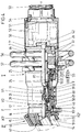
- the quick-release coupling shown in the drawing consists of a coupling half I practically forming a tap of a fuel supply point and another coupling half II seated on a tank 1 of a motor vehicle 2.
- the wall contour on the tank neck side is shown, including the tank neck chamber 3, the opening 4 of which can be closed in the usual way with the aid of a flap 5.
- tank connector 6 In a zone near the corner of the ceiling of the tank 1 there is a tank connector 6 shown in dash-dotted lines. With its free end, the coupling half II is connected, which is the vehicle side Part of the housing of the quick-release coupling designated 7 in its entirety.
- the coupling half II carries a free-standing nipple 8. This can be brought into a sealing, locked plug connection with a sleeve or bushing 9 of the coupling half I.
- the bushing 9 is firmly flanged to the housing 7.
- the flange-extending fastening means have the reference number 10.
- Each coupling half I, II contains a leak-free shut-off valve. That of the coupling half I is denoted by V1 and that of the coupling half II by V2.
- the valve body of both closure valves is in the usual way under pressure spring loading in the direction of the closed position.
- the valve spring of the shut-off valve I is designated 11, the other of the shut-off valve 12. They load the shut-off valves V1, V2 against each other, so they rest on correspondingly spaced, fixed abutments of the housing 7, namely on the ring shoulders of the same.
- the quick-release coupling is constructed in such a way that the air displaced in the tank 1 and also the gasifying fuel portion can be discharged in a fully disposable manner during the refueling process, specifically via the quick-release coupling. This is achieved by adjacent passage cross sections K1 and K2 in the housing 7.
- the passage channel cross-section designated K1 is reserved for filling liquids with diesel fuel, for example. Except in the cross-sectional area of the shut-off valves V1, V2, it (K1) takes a central course and forms the largest single cross-section of this clean-break coaxial coupling. Both passageway cross sections are pro rata from the two coupling halves I, II.
- the passage channel cross-section K2 provided for the air outlet from the filling tank 1 is accommodated in the ring area not occupied by the essentially central passage channel cross-section K1 and is provided there in pairs (see FIG. 6), namely by means of diametrically lying cable runs.
- the passage channel sections K2 'passing the coupling half II' open on the vehicle side into an annular space 13 between connecting piece 6 and a centrally located fill pipe 14 of the tank 1.
- the base body of the coupling half II which is located directly on the connecting piece, is designated by 15 . It has a socket-side recess 16 with the outside of the channel mouths of K2 'lying sealing ring 17.
- a protruding sleeve 15' attaches to the filling tube 14, which runs at a distance from the bottom of the tank 1. From the base body 15 take the two line systems, i.e. passage channel cross sections K1 and K2, an obtuse angled course - the sections K2 'and K1' fall - to the essentially horizontally aligned coupling half I.
- the flange 18 forms an annular distribution chamber 19 into which the overall channel of the passage channel cross section, which is annular here K2 flows out and from the base side then the slightly diverging aligned passage channel sections K2 'of the coupling half II emanate.
- the closure valves V1, V2 are actuated by means of an auxiliary medium, specifically via an annular piston 20 which can be acted upon on both sides or alternately.
- the latter moves in a cylinder 21 provided by the housing 7.
- the piston end positions are limited by stops.
- the surface of the annular piston 20 on the tank neck side is located in front of a proximity initiator 22.
- the latter is located in an axial bore in the flange-shaped region of the housing 7 and is electrically connected to a data registration device.
- the direct valve-side control attack is formed by a control sleeve 23, which is referred to as a tappet.
- a control sleeve 23 which is referred to as a tappet.
- This is connected to the end face of a piston shaft 24, which is designed in two parts.
- the second shaft part which forms the piston skirt and is attached by means of a flange connection, is called 25 and, with its central bore, provides a proportion of the passage channel cross section K1.
- the entire shaft 24/25 leads sealed on all sides in a central bore 26 of the housing 7 and forms sections of the passage channel cross sections K2 on the outside of the central passage channel cross section K1 through radial bores in its wall.
- the end of the shaft part 25, which forms a deflection channel section extends on the inner surface of the foot of the control sleeve 23 mentioned, and in this case is also sealed off from it.
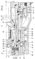
- control sleeve 23 with its body in the area of the valve locking level represents a kind of movable partition of the passage cross-sections K1, K2. see in particular Figures 3 and 5).
- the latter lies with its free end face 28 sealingly against a sealing ring 29 of the closure valve V2.
- This valve, or rather its sealing ring 29, closes both passage channel cross sections K1 and K2 in the closed position shown in FIG. 3, but also in the disconnected position.
- Said sealing ring 29 has a long rectangular cross-section and is seated with its one broad surface tired of an annular flange 30 of the shut-off valve V2 of this coupling half II on the tank neck.
- the latter are concentric and extend on a common transverse plane to the longitudinal central axis x-x of the coaxial coupling.
- the housing 7 forms an annular lock 33 receiving the head 27 and the end of the control sleeve 23 there.
- valve seat surface 31 is formed by a central valve tappet 34 associated with the closure valve V2 and connected to the nipple 8.
- the valve tappet 34 is used for the partial formation of the passage channel cross section K1 reserved for filling the liquid and is consequently of hollow design, but its piston-side end is closed.
- Cross passages 35 are located immediately behind the closing wall there.
- the surrounding jacket zone of the cross passages 35 is an annular groove-like recess 36 upstream.
- the head 27 enters with lateral, rear parts in sealing contact with the central closing valve V1 of the coupling half I, which is in the closed position and the disconnected position of the coupling.
- One part forms a valve seat surface 37 on the head side, against which the edge edge of the correspondingly spring-loaded valve body of the closure valve V1 is covered by the sealing ring.
- This movable valve seat surface 37 which is practically formed by the chin of the head 27, is designed as a rotationally symmetrical oblique flank with centering directed toward the tank neck.
- the head 27 receives a sealing ring on the wall side in an annular groove, which seals the peripheral section of the passage channel cross section K2 against an inner sleeve 38 flanged on the housing, that is to say closes when separated.
- the control sleeve is offset on the outside, facing away from the head.
- annular shaft 39 is left, into which the nipple 8 enters in a sealed manner in the course of the coupling connection.
- connection-side continuation of this channel section in the connection direction which is in the back of the quick-release coupling lies, form angular channels 41 in the thick-walled area of the housing 7.
- FIG. 6 A view of Fig. 6 illustrates the distribution of the individual connections in the back F 'of the housing 7. These are a central connection 42 for filling liquid, that is, for the passage cross section K1, two connections 43 for gas / air discharge and two connections 44 for feeding the piston / cylinder unit 20/21 with said auxiliary medium and a decentralized connection 45 for electrical lines. In all cases, it can be a screw socket to which the union ring nuts of the corresponding cable runs are assigned.
- an induction coil is located on each side of the peripheral section of a parting line F (see FIG. 7) of both coupling halves I, II.
- One is designated 46 and the other 47. They extend back to back and are embedded in corresponding annular grooves 48 of the housing 7 on the one hand and 49 of the nipple 8 on the other.
- the favorable congruent position of the housing faces facing each other is used sensibly as an information bridge.
- the induction coils 46, 47 surround the explained passage cross sections K1, K2.
- One 47 of the two induction coils 46, 47 is connected as a transmitter to an encoder (not shown) arranged in tank 1.
- the other of the two induction coils 46, 47 connects to a receiver, which in turn is connected to a data recording device (not shown). In this way, the customary refueling information and values can be displayed and used for control purposes.
- connections 42 to 45 mentioned are surrounded by a protective chamber wall 50.
- the latter is releasably connected to the back 7 'of the housing 7.
- the back-facing calculation narrows to a through opening 51 for the lines designated in their entirety by 52.
- these lines 52 are bundled and protected in a so-called flexible hose 53.
- the attachment-side end of the hose 53 carries a flange 54, which is detachably connected to the protective chamber wall 50.
- a control unit 55 which effects the program-controlled or sequence-controlled displacement process of the piston 20, is only shown schematically, as are the lines emanating from it and alternately acting on the piston along with their connections.
- the manually operable quick-release coupling has a gripping ring 56 connected to the housing.
- a second gripping ring 57 extends in front of this gripping ring, with an upstream opening.
- the latter is connected to a locking sleeve 58.
- This is spring-loaded in the direction of its locking position. It is a compression spring 59 supported on the housing side.
- Locking balls 60 serve as locking elements, which are captively located in radial bores of a ball cage on the housing side. In the decoupling position, the locking balls 60 are in an evasive position, that is to say they enter an annular groove 61 of the locking sleeve 60 provided with actuating surfaces.
- a control bevel raises the locking balls 60 to such an extent that they engage in a correspondingly located annular groove 62 on the lateral surface of the nipple 8.
- the locking sleeve side The blocking edge has the reference number 63.
- the locking sleeve 58 is withdrawn against the force of the compression spring 59, which is permanently loading it, by passing through the predetermined displacement stroke y.
- the coupling half I is then pushed onto the coupling half II, the locking balls 60 engaging in the nipple-side annular groove 62 in the correct end position.
- the locking sleeve 58 then advances.
- the locking balls are locked.
- the loops of the induction coils 46, 47 are approached to one another.
- the correctly executed blocking position is sent to the data registration device as information.
- the path for actuating the piston 20 is then opened. Its displacement on the nozzle side, caused by the auxiliary medium, moves the piston-connected locking sleeve 23.
- both passage channel cross sections K1, K2 are opened. About the passage cross section K1 and the passage section K1 'the liquid filling occurs. In return, the air displaced in the tank 1, etc., is evacuated in opposite directions via the passageway sections K2 'and passageway cross sections K2 arranged for disposal. If the information "tank full" is given via the transmitter / receiver elements, the auxiliary medium is set to reverse in a program-controlled manner. The piston 20 is thus retracted.
- a push-button actuated emergency switch 64 is assigned to the quick-release coupling lying in the protection of the gripping ring 56 on the housing side.
Landscapes
- Engineering & Computer Science (AREA)
- Mechanical Engineering (AREA)
- General Engineering & Computer Science (AREA)
- Quick-Acting Or Multi-Walled Pipe Joints (AREA)
- Hydraulic Clutches, Magnetic Clutches, Fluid Clutches, And Fluid Joints (AREA)
- Control Of Combustion (AREA)
Applications Claiming Priority (2)
| Application Number | Priority Date | Filing Date | Title |
|---|---|---|---|
| DE4036901A DE4036901A1 (de) | 1990-11-20 | 1990-11-20 | Schnellverschluss-kupplung |
| DE4036901 | 1990-11-20 |
Publications (2)
| Publication Number | Publication Date |
|---|---|
| EP0487844A1 EP0487844A1 (de) | 1992-06-03 |
| EP0487844B1 true EP0487844B1 (de) | 1994-07-13 |
Family
ID=6418589
Family Applications (1)
| Application Number | Title | Priority Date | Filing Date |
|---|---|---|---|
| EP91115036A Expired - Lifetime EP0487844B1 (de) | 1990-11-20 | 1991-09-06 | Schnellverschluss-Kupplung für Betankungsvorrichtung mit Gasrückführung |
Country Status (5)
| Country | Link |
|---|---|
| EP (1) | EP0487844B1 (da) |
| AT (1) | ATE108419T1 (da) |
| DE (2) | DE4036901A1 (da) |
| DK (1) | DK0487844T3 (da) |
| ES (1) | ES2057689T3 (da) |
Cited By (4)
| Publication number | Priority date | Publication date | Assignee | Title |
|---|---|---|---|---|
| US10975993B2 (en) | 2017-08-11 | 2021-04-13 | Norma U.S. Holding Llc | Fluid line connector and assembly with securement detection |
| US11048994B2 (en) | 2017-08-11 | 2021-06-29 | Norma U.S. Holding Llc | Fluid line connector and assembly with securement detection |
| US11199282B2 (en) | 2017-08-11 | 2021-12-14 | Norma U.S. Holding Llc | Fluid line connector and assembly with securement detection |
| US11306857B2 (en) | 2017-08-11 | 2022-04-19 | Norma U.S. Holding Llc | Fluid line connector and assembly with securement detection |
Families Citing this family (11)
| Publication number | Priority date | Publication date | Assignee | Title |
|---|---|---|---|---|
| EP0607351A1 (en) * | 1991-10-18 | 1994-07-27 | Royal Packaging Industries Van Leer N.V. | Fluid dispense system |
| US5404909A (en) * | 1992-06-11 | 1995-04-11 | Parker-Hannifin Corporation | Coupling device |
| DE4405687A1 (de) * | 1994-02-22 | 1995-08-24 | Harald Dr Ing Gruber | Betankungsanlage |
| JP2986419B2 (ja) * | 1997-02-25 | 1999-12-06 | 本田技研工業株式会社 | 燃料注入装置 |
| FR2806353B1 (fr) * | 2000-03-17 | 2002-07-12 | Staubli Sa Ets | Embout de raccord rapide, raccord rapide comprenant un tel embout et systeme de remplissage d'un reservoir embarque comprenant un tel raccord |
| DE20203248U1 (de) | 2002-03-02 | 2003-04-17 | Weh, Erwin, 89257 Illertissen | Anschlußkupplung |
| DE20203246U1 (de) | 2002-03-02 | 2003-04-17 | Weh, Erwin, 89257 Illertissen | Anschlußkupplung mit Schiebehülse und Spannzangen |
| DE20203247U1 (de) * | 2002-03-02 | 2003-04-17 | Weh, Erwin, 89257 Illertissen | Anschlußkupplung mit Datenschnittstelle |
| FR2861382B1 (fr) | 2003-10-22 | 2005-12-30 | Staubli Sa Ets | Dispositif de remplissage de reservoir de vehicule en carburant liquide |
| CA2597275A1 (en) * | 2004-08-03 | 2006-02-09 | Solution Specialists Limited | Improved fuel filling apparatus |
| CN107840300B (zh) * | 2017-09-27 | 2024-04-30 | 洛阳源和科技有限公司 | 一种流体装卸鹤管上配套双通道回转器的操作方法 |
Family Cites Families (5)
| Publication number | Priority date | Publication date | Assignee | Title |
|---|---|---|---|---|
| US3635264A (en) * | 1970-04-27 | 1972-01-18 | Outboard Marine Corp | Fueling means |
| FR2266076A1 (en) * | 1974-03-28 | 1975-10-24 | Hopfma Anstalt | Valve for draining containers by pressurised gas - connects gas supply and simultaneously opens drain |
| US4500881A (en) * | 1982-09-23 | 1985-02-19 | Liquidometer Corporation | Inductively-coupled signalling system |
| DE3831467A1 (de) * | 1987-09-17 | 1989-04-06 | Walther Carl Kurt Gmbh | Verbindungsanlage |
| US4763683A (en) * | 1987-09-21 | 1988-08-16 | Catlow, Inc. | Breakaway coupling for a coaxial fuel supply hose |
-
1990
- 1990-11-20 DE DE4036901A patent/DE4036901A1/de not_active Withdrawn
-
1991
- 1991-09-06 EP EP91115036A patent/EP0487844B1/de not_active Expired - Lifetime
- 1991-09-06 ES ES91115036T patent/ES2057689T3/es not_active Expired - Lifetime
- 1991-09-06 DE DE59102176T patent/DE59102176D1/de not_active Expired - Fee Related
- 1991-09-06 AT AT91115036T patent/ATE108419T1/de not_active IP Right Cessation
- 1991-09-06 DK DK91115036.5T patent/DK0487844T3/da active
Cited By (4)
| Publication number | Priority date | Publication date | Assignee | Title |
|---|---|---|---|---|
| US10975993B2 (en) | 2017-08-11 | 2021-04-13 | Norma U.S. Holding Llc | Fluid line connector and assembly with securement detection |
| US11048994B2 (en) | 2017-08-11 | 2021-06-29 | Norma U.S. Holding Llc | Fluid line connector and assembly with securement detection |
| US11199282B2 (en) | 2017-08-11 | 2021-12-14 | Norma U.S. Holding Llc | Fluid line connector and assembly with securement detection |
| US11306857B2 (en) | 2017-08-11 | 2022-04-19 | Norma U.S. Holding Llc | Fluid line connector and assembly with securement detection |
Also Published As
| Publication number | Publication date |
|---|---|
| DK0487844T3 (da) | 1994-11-07 |
| DE59102176D1 (de) | 1994-08-18 |
| DE4036901A1 (de) | 1992-05-21 |
| ATE108419T1 (de) | 1994-07-15 |
| EP0487844A1 (de) | 1992-06-03 |
| ES2057689T3 (es) | 1994-10-16 |
Similar Documents
| Publication | Publication Date | Title |
|---|---|---|
| EP0487844B1 (de) | Schnellverschluss-Kupplung für Betankungsvorrichtung mit Gasrückführung | |
| EP0804701B1 (de) | Schnellanschlusskupplung | |
| EP1350896B1 (de) | Ventilanordnung für einen Rohrtrenner | |
| DE3030989C2 (da) | ||
| DE3304264C2 (de) | Flüssigkeitskupplung mit Rückschlagventil | |
| DE4035453C2 (de) | Schnellverschlußkupplung für hydraulische Bremssysteme, insbesondere Anhängerkupplungen | |
| EP1483523B1 (de) | Anschlusskupplung mit schalteinheit | |
| DE10001236C1 (de) | Sicherheitsentlüftungskupplung für Druckgas, insbesondere Druckluftleitungen | |
| DE19709096A1 (de) | Ventilarmatur für einen Druckbehälter | |
| DE1650143A1 (de) | Stroemungsmittelkupplung | |
| DE29808654U1 (de) | Kupplung mit Abreißsicherung | |
| DE102011003864B4 (de) | Einsatz für den Wasserauslass aus einer Sanitärarmatur | |
| DE2302220A1 (de) | Vorrichtung zum fuellen von behaeltern | |
| DE19715868A1 (de) | Zapfschlauch-Anordnung mit einer Zapfpistole mit einem handbetätigbaren Zapfventil | |
| LU85379A1 (de) | Schnellkupplung fuer ein doppelcontainment-fluidleitungssystem | |
| DE1078826B (de) | Ventilkupplung fuer Schlauchleitungen | |
| DE1505404A1 (de) | Kupplung fuer Druckmittelleitungen | |
| DE1290017B (de) | Ventilkupplung fuer Rohr- oder Schlauchleitungen, insbesondere zum Anschluss an eine Rakete | |
| DE69202742T2 (de) | Fluiddruck-Steuerventil. | |
| DE2757003C3 (de) | Ventilkupplung | |
| DE2119941A1 (de) | Trägheitsgesteuertes Ventil | |
| DE2339397A1 (de) | Ein, insbesondere fuer zweikreisige anhaengerbremsung bestimmtes anhaengerbremsventil | |
| DE3406271C2 (da) | ||
| DE29505161U1 (de) | Verschlußventil für Absauganlagen | |
| EP0325099A1 (de) | Umschaltvorrichtung für sanitäre Armaturen |
Legal Events
| Date | Code | Title | Description |
|---|---|---|---|
| PUAI | Public reference made under article 153(3) epc to a published international application that has entered the european phase |
Free format text: ORIGINAL CODE: 0009012 |
|
| AK | Designated contracting states |
Kind code of ref document: A1 Designated state(s): AT BE CH DE DK ES FR GB GR IT LI LU NL SE |
|
| 17P | Request for examination filed |
Effective date: 19921023 |
|
| 17Q | First examination report despatched |
Effective date: 19930426 |
|
| GRAA | (expected) grant |
Free format text: ORIGINAL CODE: 0009210 |
|
| AK | Designated contracting states |
Kind code of ref document: B1 Designated state(s): AT BE CH DE DK ES FR GB GR IT LI LU NL SE |
|
| PG25 | Lapsed in a contracting state [announced via postgrant information from national office to epo] |
Ref country code: GR Free format text: LAPSE BECAUSE OF FAILURE TO SUBMIT A TRANSLATION OF THE DESCRIPTION OR TO PAY THE FEE WITHIN THE PRESCRIBED TIME-LIMIT Effective date: 19940713 |
|
| REF | Corresponds to: |
Ref document number: 108419 Country of ref document: AT Date of ref document: 19940715 Kind code of ref document: T |
|
| REF | Corresponds to: |
Ref document number: 59102176 Country of ref document: DE Date of ref document: 19940818 |
|
| ET | Fr: translation filed | ||
| GBT | Gb: translation of ep patent filed (gb section 77(6)(a)/1977) |
Effective date: 19940810 |
|
| ITF | It: translation for a ep patent filed | ||
| REG | Reference to a national code |
Ref country code: ES Ref legal event code: FG2A Ref document number: 2057689 Country of ref document: ES Kind code of ref document: T3 |
|
| REG | Reference to a national code |
Ref country code: DK Ref legal event code: T3 |
|
| EAL | Se: european patent in force in sweden |
Ref document number: 91115036.5 |
|
| PLBE | No opposition filed within time limit |
Free format text: ORIGINAL CODE: 0009261 |
|
| STAA | Information on the status of an ep patent application or granted ep patent |
Free format text: STATUS: NO OPPOSITION FILED WITHIN TIME LIMIT |
|
| 26N | No opposition filed | ||
| PGFP | Annual fee paid to national office [announced via postgrant information from national office to epo] |
Ref country code: DK Payment date: 19980807 Year of fee payment: 9 |
|
| PGFP | Annual fee paid to national office [announced via postgrant information from national office to epo] |
Ref country code: GB Payment date: 19990728 Year of fee payment: 9 |
|
| PGFP | Annual fee paid to national office [announced via postgrant information from national office to epo] |
Ref country code: LU Payment date: 19990812 Year of fee payment: 9 Ref country code: BE Payment date: 19990812 Year of fee payment: 9 Ref country code: AT Payment date: 19990812 Year of fee payment: 9 |
|
| PGFP | Annual fee paid to national office [announced via postgrant information from national office to epo] |
Ref country code: SE Payment date: 19990813 Year of fee payment: 9 Ref country code: NL Payment date: 19990813 Year of fee payment: 9 Ref country code: FR Payment date: 19990813 Year of fee payment: 9 Ref country code: CH Payment date: 19990813 Year of fee payment: 9 |
|
| PGFP | Annual fee paid to national office [announced via postgrant information from national office to epo] |
Ref country code: DE Payment date: 19990903 Year of fee payment: 9 |
|
| PGFP | Annual fee paid to national office [announced via postgrant information from national office to epo] |
Ref country code: ES Payment date: 19990920 Year of fee payment: 9 |
|
| PG25 | Lapsed in a contracting state [announced via postgrant information from national office to epo] |
Ref country code: LU Free format text: LAPSE BECAUSE OF NON-PAYMENT OF DUE FEES Effective date: 20000906 Ref country code: GB Free format text: LAPSE BECAUSE OF NON-PAYMENT OF DUE FEES Effective date: 20000906 Ref country code: DK Free format text: LAPSE BECAUSE OF NON-PAYMENT OF DUE FEES Effective date: 20000906 Ref country code: AT Free format text: LAPSE BECAUSE OF NON-PAYMENT OF DUE FEES Effective date: 20000906 |
|
| PG25 | Lapsed in a contracting state [announced via postgrant information from national office to epo] |
Ref country code: ES Free format text: LAPSE BECAUSE OF NON-PAYMENT OF DUE FEES Effective date: 20000907 |
|
| PG25 | Lapsed in a contracting state [announced via postgrant information from national office to epo] |
Ref country code: SE Free format text: THE PATENT HAS BEEN ANNULLED BY A DECISION OF A NATIONAL AUTHORITY Effective date: 20000929 |
|
| PG25 | Lapsed in a contracting state [announced via postgrant information from national office to epo] |
Ref country code: LI Free format text: LAPSE BECAUSE OF NON-PAYMENT OF DUE FEES Effective date: 20000930 Ref country code: CH Free format text: LAPSE BECAUSE OF NON-PAYMENT OF DUE FEES Effective date: 20000930 Ref country code: BE Free format text: LAPSE BECAUSE OF NON-PAYMENT OF DUE FEES Effective date: 20000930 |
|
| BERE | Be: lapsed |
Owner name: CARL KURT WALTHER G.M.B.H. & CO. K.G. Effective date: 20000930 |
|
| PG25 | Lapsed in a contracting state [announced via postgrant information from national office to epo] |
Ref country code: NL Free format text: LAPSE BECAUSE OF NON-PAYMENT OF DUE FEES Effective date: 20010401 |
|
| GBPC | Gb: european patent ceased through non-payment of renewal fee |
Effective date: 20000906 |
|
| REG | Reference to a national code |
Ref country code: CH Ref legal event code: PL |
|
| EUG | Se: european patent has lapsed |
Ref document number: 91115036.5 |
|
| REG | Reference to a national code |
Ref country code: DK Ref legal event code: EBP |
|
| PG25 | Lapsed in a contracting state [announced via postgrant information from national office to epo] |
Ref country code: FR Free format text: LAPSE BECAUSE OF NON-PAYMENT OF DUE FEES Effective date: 20010531 |
|
| NLV4 | Nl: lapsed or anulled due to non-payment of the annual fee |
Effective date: 20010401 |
|
| PG25 | Lapsed in a contracting state [announced via postgrant information from national office to epo] |
Ref country code: DE Free format text: LAPSE BECAUSE OF NON-PAYMENT OF DUE FEES Effective date: 20010601 |
|
| REG | Reference to a national code |
Ref country code: FR Ref legal event code: ST |
|
| REG | Reference to a national code |
Ref country code: ES Ref legal event code: FD2A Effective date: 20011011 |
|
| PG25 | Lapsed in a contracting state [announced via postgrant information from national office to epo] |
Ref country code: IT Free format text: LAPSE BECAUSE OF NON-PAYMENT OF DUE FEES;WARNING: LAPSES OF ITALIAN PATENTS WITH EFFECTIVE DATE BEFORE 2007 MAY HAVE OCCURRED AT ANY TIME BEFORE 2007. THE CORRECT EFFECTIVE DATE MAY BE DIFFERENT FROM THE ONE RECORDED. Effective date: 20050906 |