EP0487907A1 - Dispositif de positionnement pour mettre des bobines, en particulier de bande métallique, sur un mandrin de dévidage - Google Patents
Dispositif de positionnement pour mettre des bobines, en particulier de bande métallique, sur un mandrin de dévidage Download PDFInfo
- Publication number
- EP0487907A1 EP0487907A1 EP91118308A EP91118308A EP0487907A1 EP 0487907 A1 EP0487907 A1 EP 0487907A1 EP 91118308 A EP91118308 A EP 91118308A EP 91118308 A EP91118308 A EP 91118308A EP 0487907 A1 EP0487907 A1 EP 0487907A1
- Authority
- EP
- European Patent Office
- Prior art keywords
- collar
- reel drum
- measuring head
- positioning device
- coil
- Prior art date
- Legal status (The legal status is an assumption and is not a legal conclusion. Google has not performed a legal analysis and makes no representation as to the accuracy of the status listed.)
- Granted
Links
Images

Classifications
-
- B—PERFORMING OPERATIONS; TRANSPORTING
- B65—CONVEYING; PACKING; STORING; HANDLING THIN OR FILAMENTARY MATERIAL
- B65H—HANDLING THIN OR FILAMENTARY MATERIAL, e.g. SHEETS, WEBS, CABLES
- B65H19/00—Changing the web roll
- B65H19/10—Changing the web roll in unwinding mechanisms or in connection with unwinding operations
- B65H19/12—Lifting, transporting, or inserting the web roll; Removing empty core
- B65H19/123—Lifting, transporting, or inserting the web roll; Removing empty core with cantilever supporting arrangements
-
- B—PERFORMING OPERATIONS; TRANSPORTING
- B21—MECHANICAL METAL-WORKING WITHOUT ESSENTIALLY REMOVING MATERIAL; PUNCHING METAL
- B21C—MANUFACTURE OF METAL SHEETS, WIRE, RODS, TUBES, PROFILES OR LIKE SEMI-MANUFACTURED PRODUCTS OTHERWISE THAN BY ROLLING; AUXILIARY OPERATIONS USED IN CONNECTION WITH METAL-WORKING WITHOUT ESSENTIALLY REMOVING MATERIAL
- B21C47/00—Winding-up, coiling or winding-off metal wire, metal band or other flexible metal material characterised by features relevant to metal processing only
- B21C47/24—Transferring coils to or from winding apparatus or to or from operative position therein; Preventing uncoiling during transfer
-
- B—PERFORMING OPERATIONS; TRANSPORTING
- B65—CONVEYING; PACKING; STORING; HANDLING THIN OR FILAMENTARY MATERIAL
- B65H—HANDLING THIN OR FILAMENTARY MATERIAL, e.g. SHEETS, WEBS, CABLES
- B65H2301/00—Handling processes for sheets or webs
- B65H2301/40—Type of handling process
- B65H2301/41—Winding, unwinding
- B65H2301/413—Supporting web roll
- B65H2301/4132—Cantilever arrangement
- B65H2301/41324—Cantilever arrangement linear movement of roll support
-
- B—PERFORMING OPERATIONS; TRANSPORTING
- B65—CONVEYING; PACKING; STORING; HANDLING THIN OR FILAMENTARY MATERIAL
- B65H—HANDLING THIN OR FILAMENTARY MATERIAL, e.g. SHEETS, WEBS, CABLES
- B65H2301/00—Handling processes for sheets or webs
- B65H2301/40—Type of handling process
- B65H2301/41—Winding, unwinding
- B65H2301/417—Handling or changing web rolls
- B65H2301/4171—Handling web roll
- B65H2301/41745—Handling web roll by axial movement of roll
Definitions
- the invention relates to a positioning device for bundles to be placed on a reel drum, in particular made of metal strip, consisting of a lifting carriage for the coil and a measuring device for detecting the position of the inner coil diameter, the measured values of which are a control device for height adjustment and for moving the lifting carriage relative to the reel drum recycled.
- the cause of such a collision can be that when the position of the inner diameter is detected indirectly via the outer diameter, the inner diameter is eccentric to the outer diameter. If the inside diameter is recorded directly at diametrically opposite points, collisions can occur because the inside diameter is oval-shaped and / or the inside winding protrudes laterally inwards with the beginning of the strip and / or the inside diameter is offset eccentrically to the side.
- a further error when attaching the collar can be that the beginning of the band or the band tongue does not get into the recess provided for this on the reel. When the reel spreader is spread, this means that the bundle sits eccentrically on the reel drum, which can lead to fluctuations in tape tension when the bundle runs out of the reel drum.
- the invention has for its object to provide a positioning device for bundles to be placed on a reel drum, which ensures trouble-free placement of the bundles on the reel drum.
- the measuring device has a 360 o be measured, the inner contour of the Federal sensing measuring head and the control device from a comparison of said contour with corresponding values for the coiling drum actuators for the height adjustment of the lifting carriage and / or the lateral displacement of the bundle on the pallet truck and / or the relative rotation between the collar and the reel drum.
- the inside diameter of the collar is measured over the entire circumference, so that it can be determined by comparison with the corresponding values for the reel drum whether there is sufficient play between the inside diameter of the collar and the reel drum over the entire circumference for trouble-free attachment exists or not.
- the collar can be positioned using the various positioning movements so that the overlaps are eliminated.
- the correction can be carried out with one or more adjustment processes.
- the measuring head is adjustable in the direction of the collar axis to detect the position of the collar on the pallet truck the control device determines the travel of the lifting truck as a function of these measured values.
- the measuring head can be set up to detect the end face of the collar and can be adjusted radially to the collar. A possible axial offset of the collar can be determined from the distance values found in this way and taken into account when determining the travel path.
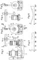
- a lifting carriage 3 In order to push a collar 1 onto a reel drum 2, a lifting carriage 3 is provided, which can be moved on rails between a receiving position shown on the right in FIG. 1 and a transfer position shown on the left in FIG. 1.
- the pallet truck 3 is with a height and side-adjustable, trough-shaped support element 5, on which the collar 1 rests during the process.
- rollers 6, 7 arranged parallel to one another on both sides are provided as support and centering elements for the collar 1. With the support element 5 lowered, it is possible to rotate the collar 1 with these rollers 6, 7.
- a carriage 9 can be moved on a rail 8 by means of a drive 10.
- the carriage 9 carries, on an arm 11, a measuring device 13 with a rotating measuring head 13.
- the measuring head 13 comprises a distance sensor 13a.
- the measuring head 13 can be moved into the inner opening of the collar 1 by means of the driven slide 9.
- the inner contour of the collar 1 can then be detected by means of the measuring head 13.
- An inwardly projecting band tongue 14 is also detected.
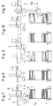
- FIG. 3 shows the diagram of the inner contour recorded in this way.
- the diagram shows that the band tongue 14 is at about 300 o . Since the diagram provides a constant value, the figure is centered on the measuring head and circular.
- This measurement result is delivered to the control device, which compares it with the position of the reel drum 2. Since the central opening of the collar 1 is already centered, only height positioning and possibly a twisting of the collar with regard to a recess on the circumference of the reel drum 2 are considered for the band tongue 14.
- Figures 4 and 5 differs from that of Figures 1 and 2 only in that the collar 1 'has a smaller outer diameter.
- the result is that the inner diameter of the collar 1 'is eccentric with respect to the fixed measuring head 12. This is also expressed in the diagram in FIG. 6.
- the eccentricity can be determined by comparing the values 0 o / 360 o and 180 o , so that, depending on this eccentricity, the lifting truck 3 can be raised until the central opening is eccentric. If the measurement were repeated, the diagram in FIG. 3 would be measured.
- FIGS. 7 to 11 show that the measuring device 12 can be adjusted in height with the measuring head 13 and moved axially over the collar 1. 7, the measuring head 13 is moved axially.
- a distance meter integrated in the drive 10 delivers corresponding measured values to the control device.
- the travel path begins from the initial position shown in FIG. 7.
- a first signal is delivered when the distance sensor 13a strikes the front edge of the bundle 1, that is the position in FIG. 8.
- the path covered so far is recorded because it provides information about the position of the bundle 1 on the pallet truck 3.
- a second signal is provided when the distance sensor 13a leaves the rear edge of the collar 1.
- the value between these two signals is the fret width b.
- the control device can determine the travel path of the bundle 1 placed in any axial position on the lifting truck 3, so that the bundle is plugged onto the reel drum 2 in a specific desired axial position.
- the measuring head 12 After the axial position of the collar 1 on the pallet truck 3 and the width of the collar 1 have been detected, the measuring head 12 is moved into the position for detecting the inner contour of the collar 1, as shown in FIG. The previously recorded measured values are used for this positioning. Since the measuring head 13 has the distance sensor 13a, it also detects the distance h 1 from the apex of the federal government 1. Taking into account its known distance h 1 from the supporting element 5, the distance h m can be determined in the measuring device in order to move the measuring head 13 to the central position , as shown in Figure 11. This position corresponds to that in Figure 1.
- the measuring head 13, as shown in FIGS. 12 to 14, can be equipped with a further distance sensor 13b arranged on the end face.
- the end face of the collar 1 can be detected with this distance sensor 13b.
- This measurement is used to record any axial displacements of the individual layers of the federal government 1, but it can also be used to record the top and bottom vertices of the inner opening.
- the detection of a possible layer shift is important in connection with the detection of the width b. If the outer layers are axially offset from one another, the distance sensor 13a which detects the width does not determine the actual width, but rather a larger width. This incorrect measurement result can be corrected by detecting the end face, so that, as a result, the collar 1 can be positioned axially correctly on the reel drum 2.
- the position value h m for the measuring head 13 for detecting the inner contour can also be determined, so that the measuring device detects a diagram corresponding to FIG. 15 for a circular, non-offset contour.
Landscapes
- Engineering & Computer Science (AREA)
- Mechanical Engineering (AREA)
- Winding, Rewinding, Material Storage Devices (AREA)
- Length Measuring Devices With Unspecified Measuring Means (AREA)
- Replacement Of Web Rolls (AREA)
- Storage Of Web-Like Or Filamentary Materials (AREA)
- Manipulator (AREA)
Applications Claiming Priority (2)
| Application Number | Priority Date | Filing Date | Title |
|---|---|---|---|
| DE4037671A DE4037671A1 (de) | 1990-11-27 | 1990-11-27 | Positioniervorrichtung fuer auf eine haspeltrommel aufzusteckende bunde, insbesondere aus metallband |
| DE4037671 | 1990-11-27 |
Publications (2)
| Publication Number | Publication Date |
|---|---|
| EP0487907A1 true EP0487907A1 (fr) | 1992-06-03 |
| EP0487907B1 EP0487907B1 (fr) | 1995-02-08 |
Family
ID=6418988
Family Applications (1)
| Application Number | Title | Priority Date | Filing Date |
|---|---|---|---|
| EP91118308A Expired - Lifetime EP0487907B1 (fr) | 1990-11-27 | 1991-10-28 | Dispositif de positionnement pour mettre des bobines, en particulier de bande métallique, sur un mandrin de dévidage |
Country Status (5)
| Country | Link |
|---|---|
| US (1) | US5248109A (fr) |
| EP (1) | EP0487907B1 (fr) |
| JP (1) | JPH04268408A (fr) |
| AT (1) | ATE118198T1 (fr) |
| DE (2) | DE4037671A1 (fr) |
Cited By (5)
| Publication number | Priority date | Publication date | Assignee | Title |
|---|---|---|---|---|
| EP0708048A1 (fr) * | 1994-09-21 | 1996-04-24 | Bayer Corporation | Méthode et appareil pour installer une cassette d'alimentation de supports dans un compositeur d'image |
| EP0697359A3 (fr) * | 1994-08-19 | 1997-02-05 | Sucker Mueller Hacoba Gmbh | Procédé de serrage d'un arbre porte-bobine |
| EP0775659A3 (fr) * | 1992-06-30 | 1997-07-30 | Focke & Co | Dispositif pour manipuler des bobines de bandes |
| EP0995706A1 (fr) * | 1998-10-13 | 2000-04-26 | Hauni Maschinenbau AG | Changeur de bobines |
| EP1074472B1 (fr) * | 1997-03-14 | 2002-11-06 | Focke & Co. (GmbH & Co.) | Dispositif pour transporter des bobines de materiau d'emballage |
Families Citing this family (13)
| Publication number | Priority date | Publication date | Assignee | Title |
|---|---|---|---|---|
| US5315700A (en) * | 1992-02-18 | 1994-05-24 | Neopath, Inc. | Method and apparatus for rapidly processing data sequences |
| KR0162970B1 (ko) * | 1993-03-01 | 1998-12-01 | 에모또 간지 | 스태카 크레인의 포크장치와 그 제어방법 및 제어장치 |
| US5655870A (en) * | 1993-03-01 | 1997-08-12 | Kawasaki Steel Corporation | Stacker crane in a warehouse |
| DE19535568C1 (de) * | 1995-09-13 | 1997-04-10 | Mannesmann Ag | Anlage zum Coilhandling zwischen einem Coilmagazin und einem vor einer Weiterverarbeitungsanlage angeordneten Abwickelhaspel |
| FI105803B (fi) * | 1999-03-30 | 2000-10-13 | Valmet Corp | Menetelmä ja laitteisto paperirullan jatkuvatoimisessa aukirullauksessa |
| DE102004006659A1 (de) * | 2004-02-11 | 2005-09-08 | Koenig & Bauer Ag | Rollenwechsler und Verfahren zum Betrieb eines Rollenwechslers |
| US9969587B2 (en) | 2014-08-28 | 2018-05-15 | The Procter & Gamble Company | Web material unwind apparatus |
| US10898211B2 (en) | 2015-01-14 | 2021-01-26 | Crossroads Extremity Systems, Llc | Opening and closing wedge osteotomy guide and method |
| JP6292150B2 (ja) * | 2015-03-16 | 2018-03-14 | Jfeスチール株式会社 | アンローダ設備のコイル持上げ検出方法および装置 |
| JP7355000B2 (ja) * | 2020-12-17 | 2023-10-03 | Jfeスチール株式会社 | コイルの挿入方法および装置 |
| CN112660733A (zh) * | 2020-12-29 | 2021-04-16 | 上海骄成机电设备有限公司 | 自动上料装置 |
| EP4067274B1 (fr) * | 2021-03-31 | 2023-12-20 | Primetals Technologies Austria GmbH | Manipulation sécurisée des manchons ou bobines métalliques présentant un petit diamètre extérieur sur un mandrin de bobineuse |
| DE102023136651A1 (de) * | 2023-12-22 | 2025-06-26 | Voestalpine Stahl Gmbh | Verfahren zum Behandeln von Warmbandcoils und Vorrichtung hierfür |
Citations (2)
| Publication number | Priority date | Publication date | Assignee | Title |
|---|---|---|---|---|
| DE8501277U1 (de) * | 1985-01-19 | 1988-11-17 | Niepmann Traylift Transportsysteme GmbH & Co KG, 5820 Gevelsberg | Vorrichtung zum Entladen einzelner Bobinen von einer Unterlage |
| WO1989008598A1 (fr) * | 1988-03-10 | 1989-09-21 | Cams S.R.L. | Appareil de chargement automatique de rouleaux de papier et d'autres materiaux |
Family Cites Families (13)
| Publication number | Priority date | Publication date | Assignee | Title |
|---|---|---|---|---|
| GB1155386A (en) * | 1965-10-25 | 1969-06-18 | United Eng Foundry Co | Coil Handling Apparatus |
| DE1266094B (de) * | 1966-08-18 | 1968-04-11 | Demag Ag | Einrichtung zur automatischen Zentrierung eines Metallband-Bundes zum Dorn einer Haspelstation |
| AT277124B (de) * | 1967-11-06 | 1969-12-10 | Voest Ag | Vorrichtung zum Aufbringen von Bunden auf eine Abwickelhaspel |
| JPS5240942B2 (fr) * | 1972-06-14 | 1977-10-15 | ||
| JPS55136511A (en) * | 1979-04-13 | 1980-10-24 | Hitachi Ltd | Aligning apparatus for width of coil |
| JPS61269933A (ja) * | 1985-05-24 | 1986-11-29 | Mitsubishi Electric Corp | コイル転倒防止装置 |
| JPS62187517A (ja) * | 1987-01-09 | 1987-08-15 | Nippon Kokan Kk <Nkk> | 移動コイルのセンタリング方法 |
| JPS6451317A (en) * | 1987-08-22 | 1989-02-27 | Agency Ind Science Techn | Production of ammonia |
| JPH0630304B2 (ja) * | 1987-09-05 | 1994-04-20 | 富士電機株式会社 | 変圧器 |
| JPS6466017A (en) * | 1987-09-07 | 1989-03-13 | Mitsubishi Electric Corp | Preventing device for coil tumbling on coil car |
| JPH026016A (ja) * | 1988-06-27 | 1990-01-10 | Kawasaki Steel Corp | コイルの装着異常検出方法 |
| DE3822572A1 (de) * | 1988-07-04 | 1990-02-22 | Kleinewefers Gmbh | Rollen-abwickelvorrichtung, insbesondere fuer eine druckmaschine |
| JP2523375B2 (ja) * | 1989-06-15 | 1996-08-07 | 株式会社小松製作所 | 液晶調光素子 |
-
1990
- 1990-11-27 DE DE4037671A patent/DE4037671A1/de active Granted
-
1991
- 1991-10-28 DE DE59104543T patent/DE59104543D1/de not_active Expired - Fee Related
- 1991-10-28 EP EP91118308A patent/EP0487907B1/fr not_active Expired - Lifetime
- 1991-10-28 AT AT91118308T patent/ATE118198T1/de active
- 1991-10-30 US US07/785,319 patent/US5248109A/en not_active Expired - Fee Related
- 1991-11-26 JP JP3310824A patent/JPH04268408A/ja active Pending
Patent Citations (2)
| Publication number | Priority date | Publication date | Assignee | Title |
|---|---|---|---|---|
| DE8501277U1 (de) * | 1985-01-19 | 1988-11-17 | Niepmann Traylift Transportsysteme GmbH & Co KG, 5820 Gevelsberg | Vorrichtung zum Entladen einzelner Bobinen von einer Unterlage |
| WO1989008598A1 (fr) * | 1988-03-10 | 1989-09-21 | Cams S.R.L. | Appareil de chargement automatique de rouleaux de papier et d'autres materiaux |
Non-Patent Citations (2)
| Title |
|---|
| PATENT ABSTRACTS OF JAPAN vol. 12, no. 164 (M-698)(3011) 18. Mai 1988 & JP-A-62 280 151 ( MITSUBISHI HEAVY IND. LTD. ) 5. Dezember 1987 * |
| PATENT ABSTRACTS OF JAPAN vol. 12, no. 73 (M-674)(2920) 8. März 1988 & JP-A-62 215 451 ( YASKAWA ELECTRIC MFG CO LTD ) 22. September 1987 * |
Cited By (6)
| Publication number | Priority date | Publication date | Assignee | Title |
|---|---|---|---|---|
| EP0775659A3 (fr) * | 1992-06-30 | 1997-07-30 | Focke & Co | Dispositif pour manipuler des bobines de bandes |
| EP0697359A3 (fr) * | 1994-08-19 | 1997-02-05 | Sucker Mueller Hacoba Gmbh | Procédé de serrage d'un arbre porte-bobine |
| EP0708048A1 (fr) * | 1994-09-21 | 1996-04-24 | Bayer Corporation | Méthode et appareil pour installer une cassette d'alimentation de supports dans un compositeur d'image |
| EP1074472B1 (fr) * | 1997-03-14 | 2002-11-06 | Focke & Co. (GmbH & Co.) | Dispositif pour transporter des bobines de materiau d'emballage |
| EP0995706A1 (fr) * | 1998-10-13 | 2000-04-26 | Hauni Maschinenbau AG | Changeur de bobines |
| US6402083B1 (en) | 1998-10-13 | 2002-06-11 | Hauni Maschinenbau Ag | Bobbin loading and unloading apparatus |
Also Published As
| Publication number | Publication date |
|---|---|
| DE59104543D1 (de) | 1995-03-23 |
| JPH04268408A (ja) | 1992-09-24 |
| EP0487907B1 (fr) | 1995-02-08 |
| US5248109A (en) | 1993-09-28 |
| DE4037671A1 (de) | 1992-06-04 |
| ATE118198T1 (de) | 1995-02-15 |
| DE4037671C2 (fr) | 1993-05-19 |
Similar Documents
| Publication | Publication Date | Title |
|---|---|---|
| EP0487907B1 (fr) | Dispositif de positionnement pour mettre des bobines, en particulier de bande métallique, sur un mandrin de dévidage | |
| DE60015853T2 (de) | Halterung für Reifen und Verfahren zum Greifen derselben | |
| DE3687229T2 (de) | Zufuhrsystem eines bandes zu einer fertigungslinie. | |
| DE2556484C3 (de) | Kabelwickelmaschine | |
| WO2003079772A1 (fr) | Procede permettant de faire fonctionner un dispositif de traite et dispositif de traite | |
| EP0419822A2 (fr) | Organe de commande pour connecter lisière à lisière une nappe de tissu sortant du rouleau dévidant avec le commencement du rouleau nouveau d'une nappe de tissu | |
| DE1945840A1 (de) | Verfahren und Fuehler zum Erfassen der Lage des Endes eines Rundbunds aus Bandmaterial | |
| EP2305864B1 (fr) | Procédé de fonctionnement d'un agrégat de service et agrégat de service | |
| DE102018131305A1 (de) | Verfahren zum Anziehen von Schraubverbindungen | |
| EP0460712A2 (fr) | Méthode et dispositif pour poser des bandes de tissu ayant des défauts | |
| EP0033310B1 (fr) | Dispositif de mesure prévu à un chemin de roulement formé de rouleaux montés à rotation et méthode pour l'interprétation de la valeur mesurée | |
| EP0849181B1 (fr) | Dispositif et procédé pour emballer un rouleau de matériau en bande | |
| DE112017007612T5 (de) | Reifenfördervorrichtung, damit ausgestattetes Reifeninspektionssystem sowie Reifenförderverfahren | |
| EP0453909B1 (fr) | Procédé pour le positionnement et le réglage d'une plieuse | |
| DE4415544C1 (de) | Vorrichtung zur Erfassung und Korrektur der Verdrehung des zu einem Schlauch geschlossenen Fördergurtes eines Schlauchgurtförderers | |
| DE2145179C2 (de) | Vorrichtung zum automatischen zentrischen Ausrichten eines Bunds aus Bandmaterial zur Achse einer Abwickelmaschine | |
| EP0569719A1 (fr) | Système de transport de bande | |
| DE2007729A1 (de) | Verfahren und Vorrichtung zum automatischen Ausrichten einer Spule | |
| EP0017186A1 (fr) | Bobine démontable pour l'enroulement, en particulier de fils, et procédé pour monter un roule du sur une telle bobine | |
| DE3789254T2 (de) | Verfahren und Anlage zum Beschicken einer Abwickelvorrichtung mit einem Metallbandbund und zum Abwickeln des Metallbandes. | |
| DE2354117A1 (de) | Verfahren und vorrichtung zum messen der von einem durch eine rohrleitung bewegten inspektionsgeraet zurueckgelegten strecke | |
| DE2111213C2 (de) | Einrichtung zur berührungslosen Messung der Dicke einer Schicht aus Isoliermaterial über einem metallischen Teil | |
| DE4443503A1 (de) | Verfahren und Vorrichtung zur Drahtzuführung | |
| DE3438178C2 (fr) | ||
| DE4411366B4 (de) | Verfahren zum Aufnehmen und Transportieren einer Rolle aus aufgewickeltem Streifenmaterial zwischen zwei Funktionsstationen |
Legal Events
| Date | Code | Title | Description |
|---|---|---|---|
| PUAI | Public reference made under article 153(3) epc to a published international application that has entered the european phase |
Free format text: ORIGINAL CODE: 0009012 |
|
| AK | Designated contracting states |
Kind code of ref document: A1 Designated state(s): AT DE ES FR GB IT SE |
|
| 17P | Request for examination filed |
Effective date: 19920520 |
|
| 17Q | First examination report despatched |
Effective date: 19940329 |
|
| GRAA | (expected) grant |
Free format text: ORIGINAL CODE: 0009210 |
|
| AK | Designated contracting states |
Kind code of ref document: B1 Designated state(s): AT DE ES FR GB IT SE |
|
| PG25 | Lapsed in a contracting state [announced via postgrant information from national office to epo] |
Ref country code: IT Free format text: LAPSE BECAUSE OF FAILURE TO SUBMIT A TRANSLATION OF THE DESCRIPTION OR TO PAY THE FEE WITHIN THE PRE;WARNING: LAPSES OF ITALIAN PATENTS WITH EFFECTIVE DATE BEFORE 2007 MAY HAVE OCCURRED AT ANY TIME BEFORE 2007. THE CORRECT EFFECTIVE DATE MAY BE DIFFERENT FROM THE ONE RECORDED.SCRIBED TIME-LIMIT Effective date: 19950208 Ref country code: ES Free format text: THE PATENT HAS BEEN ANNULLED BY A DECISION OF A NATIONAL AUTHORITY Effective date: 19950208 |
|
| REF | Corresponds to: |
Ref document number: 118198 Country of ref document: AT Date of ref document: 19950215 Kind code of ref document: T |
|
| GBT | Gb: translation of ep patent filed (gb section 77(6)(a)/1977) |
Effective date: 19950211 |
|
| REF | Corresponds to: |
Ref document number: 59104543 Country of ref document: DE Date of ref document: 19950323 |
|
| ET | Fr: translation filed | ||
| PG25 | Lapsed in a contracting state [announced via postgrant information from national office to epo] |
Ref country code: SE Effective date: 19950508 |
|
| PG25 | Lapsed in a contracting state [announced via postgrant information from national office to epo] |
Ref country code: AT Effective date: 19951028 |
|
| PLBE | No opposition filed within time limit |
Free format text: ORIGINAL CODE: 0009261 |
|
| STAA | Information on the status of an ep patent application or granted ep patent |
Free format text: STATUS: NO OPPOSITION FILED WITHIN TIME LIMIT |
|
| 26N | No opposition filed | ||
| PGFP | Annual fee paid to national office [announced via postgrant information from national office to epo] |
Ref country code: FR Payment date: 19961016 Year of fee payment: 6 Ref country code: GB Payment date: 19961016 Year of fee payment: 6 |
|
| PGFP | Annual fee paid to national office [announced via postgrant information from national office to epo] |
Ref country code: DE Payment date: 19961203 Year of fee payment: 6 |
|
| PG25 | Lapsed in a contracting state [announced via postgrant information from national office to epo] |
Ref country code: GB Free format text: LAPSE BECAUSE OF NON-PAYMENT OF DUE FEES Effective date: 19971028 |
|
| PG25 | Lapsed in a contracting state [announced via postgrant information from national office to epo] |
Ref country code: FR Free format text: THE PATENT HAS BEEN ANNULLED BY A DECISION OF A NATIONAL AUTHORITY Effective date: 19971031 |
|
| GBPC | Gb: european patent ceased through non-payment of renewal fee |
Effective date: 19971028 |
|
| PG25 | Lapsed in a contracting state [announced via postgrant information from national office to epo] |
Ref country code: DE Free format text: LAPSE BECAUSE OF NON-PAYMENT OF DUE FEES Effective date: 19980701 |
|
| REG | Reference to a national code |
Ref country code: FR Ref legal event code: ST |