EP0487920A1 - Komponente mit positiven Temperaturkoeffizienten - Google Patents
Komponente mit positiven Temperaturkoeffizienten Download PDFInfo
- Publication number
- EP0487920A1 EP0487920A1 EP91118512A EP91118512A EP0487920A1 EP 0487920 A1 EP0487920 A1 EP 0487920A1 EP 91118512 A EP91118512 A EP 91118512A EP 91118512 A EP91118512 A EP 91118512A EP 0487920 A1 EP0487920 A1 EP 0487920A1
- Authority
- EP
- European Patent Office
- Prior art keywords
- ptc element
- polymer composition
- electrodes
- element according
- electrode
- Prior art date
- Legal status (The legal status is an assumption and is not a legal conclusion. Google has not performed a legal analysis and makes no representation as to the accuracy of the status listed.)
- Granted
Links
Images


Classifications
-
- H—ELECTRICITY
- H01—ELECTRIC ELEMENTS
- H01C—RESISTORS
- H01C7/00—Non-adjustable resistors formed as one or more layers or coatings; Non-adjustable resistors made from powdered conducting material or powdered semi-conducting material with or without insulating material
- H01C7/02—Non-adjustable resistors formed as one or more layers or coatings; Non-adjustable resistors made from powdered conducting material or powdered semi-conducting material with or without insulating material having positive temperature coefficient
- H01C7/027—Non-adjustable resistors formed as one or more layers or coatings; Non-adjustable resistors made from powdered conducting material or powdered semi-conducting material with or without insulating material having positive temperature coefficient consisting of conducting or semi-conducting material dispersed in a non-conductive organic material
-
- H—ELECTRICITY
- H01—ELECTRIC ELEMENTS
- H01C—RESISTORS
- H01C1/00—Details
- H01C1/14—Terminals or tapping points specially adapted for resistors; Arrangements of terminals or tapping points on resistors
- H01C1/1406—Terminals or electrodes formed on resistive elements having positive temperature coefficient
-
- H—ELECTRICITY
- H02—GENERATION; CONVERSION OR DISTRIBUTION OF ELECTRIC POWER
- H02H—EMERGENCY PROTECTIVE CIRCUIT ARRANGEMENTS
- H02H3/00—Emergency protective circuit arrangements for automatic disconnection directly responsive to an undesired change from normal electric working condition with or without subsequent reconnection ; integrated protection
- H02H3/02—Details
- H02H3/025—Disconnection after limiting, e.g. when limiting is not sufficient or for facilitating disconnection
Definitions
- the invention relates to a PTC element according to the precharacterising part of claim 1.
- a PTC element often comprises a body, provided with two parallel end surfaces, of an electrically conductive polymer composition with a *restivity with a positive temperature coefficient and two electrodes, arranged in contact with the end surfaces, for carrying current through the body, the polymer composition comprising a polymer material and an electrically conductive powdered material distributed in the polymer material.
- the expression PTC element is the accepted term for an element whose resistivity has a positive temperature coefficient. PTC elements are used in electric circuits as overcurrent protection.
- the resistance of a PTC element of the above described kind is low, for example a few m ⁇ , in the normal operating range of the element, which may extend to, for example, 80°C, and increases slightly with the temperature. If the temperature of the element exceeds this value, for example because of an overcurrent, the resistance increases more rapidly, and when exceeding a certain temperature, the element suddenly changes from a low resistance to a high resistance state, in which the resistance may amount to one or a few tens of k ⁇ . It is well-known that the resistance of the PTC element, after changing from low resistance to high resistance state, does not return to the initial resistance.
- the aim has been to secure the electrodes as efficiently as possible to the body of polymer composition to achieve the best possible electrical contact and hence minimize the contact resistance.
- they are normally formed with an uneven surface structure on the side facing the body of polymer composition, so that the polymer composition during the manufacturing of the PTC element is able to melt and penetrate into cavities in the electrode surface.
- the electrodes consist of metal foils and are applied by being pressed onto the body under heating.
- the invention aims at developing a PTC element of the above-mentioned kind, which does not loose its favorable properties after it has changed from the low resistance state to high resistance state under operation.
- the above result is obtained by producing at least one electrical contact between an electrode and a body of electrically conductive polymer composition or between two bodies of electrically conductive polymer composition in the PTC element by the electrode making free contact with the mentioned body or that the mentioned bodies make free contact with each other while maintaining a pressure directed perpendicular to the contact surface in question by means of a pressure device.
- a feasible explanation of the result obtained according to the invention may be the following.
- a low contact resistance is maintained between the elements which make free contact with each other due to the pressure exerted on the contact surface.
- electrodynamic repulsion forces occur between the elements making free contact with each other, which leads to a separation of the elements and hence a reduction of the number of contact points between electrode and conducting particles in the body of the polymer composition making free contact therewith or between conducting particles in bodies of the polymer composition making free contact with each other.
- the polymer composition maybe of a known kind and its composition or constituents constitute no part of the present invention.
- the polymer material may consist of thermoplastic resins, *elstomers, thermosetting resins or mixtures thereof, used in prior art polymer compositions with PTC behaviour.
- suitable polymer materials may be particularly mentioned polyolefins such as polyethylene, crosslinked polyethylene, polypropylene, polybutene and copolymers or ethylene and propylene.
- the polymer material preferably has a crystallinity of at least 5%.
- the conducting powdered material preferably consists of conducting carbon black or conducting soot.
- a suitable particle size of the powdered material is 0.01 to 10 ⁇ m and a suitable content of the powdered filler is 10 to 60 per cent of the total volume of the powdered filler and the polymer material.
- the *restivity of the polymer composition is preferably within the range of 10 m ⁇ cm to 100 ⁇ cm and has the ability, after a transition, to exhibit a resistivity of 1 ⁇ cm to 1 k ⁇ cm. If more than one body of electrically conductive polymer composition is included in the PTC element, the bodies may be of the same or different polymer composition and then with the same or different resistivity.
- such an electrode or such electrodes may be of a conventional kind. They may consist of metal foils or of thin metal plates or metal nettings which are rolled on the polymer composition in heated state or fixed in some other way thereto, such as by spraying or vapour deposition. Usually, the surface facing the polymer composition has an irregular structure.
- the electrodes may also consist of a combination of two or more elements, for example a thin foil of nickel and a thicker plate of copper fixed thereto.
- such fixed electrodes may consist of a tight plate or foil or metal, which on the side facing the polymer composition is coated with a layer of metal with an irregular surface structure, applied by thermal spraying such as plasma spraying, flame spraying or arc spraying, which metal layer comprises protruding portions with a height of 1 to 50 ⁇ m and a width of 1 to 50 ⁇ m.
- such an electrode may in itself, that is, apart from the fact that it is not fixed to the body of conducting polymer composition, be of the same kind as indicated in the preceding paragraph. It may also consist of a more or less thick plate with a surface with an even structure facing the body of conducting polymer composition. It is also possible, per se, to use other high conductivity materials than metallic materials in the electrodes, such as polymer material containing very high contents of electrically conductive powdered fillers, such as conducting carbon black, conducting soot, copper or nickel.
- the pressure which is maintained on the electrodes perpendicularly to the parallel surfaces on the body, or bodies, of polymer composition preferably amounts to at least 0.1 MPa. Especially preferred is a pressure of 0.1 MPa to 10 MPa.
- the pressure on the electrodes of the PTC element may be achieved purely mechanically or by utilizing forces generated by electric currents.
- the pressure device may, for example, consist of two plates arranged in parallel with the parallel surfaces of the body, or bodies, of electrically conductive polymer composition and arranged outside the electrodes, and of drawing devices or clamping devices arranged in or adjacent the plates.
- the pressure device may comprise plates of high conductivity material making contact with the electrodes, in which the current paths are adapted to be substantially parallel to the parallel surfaces of the body, or bodies, and directed in substantially the same direction as the plates, or yokes of a ferromagnetic material arranged outside the plates of high conductivity material.
- the pressure device is provided with pressure-exerting devices with the ability to be resilient.
- the pressure device significantly facilitates a separation of the electrode and the body of polymer composition making free contact with each other, or of bodies of polymer composition making free contact with each other, at short-circuit currents.
- the pressure device comprises two pressure-exerting parts, making contact with the electrodes of the PTC element by abutment, and a layer of rubber or another elastic material, for example an elastic plastic, is arranged between one of the electrodes and one of the pressure-exerting parts.
- the pressure device comprises parts exerting pressure against the electrodes of the PTC element, and at least one resilient element arranged between the pressure-exerting parts outside an electrode.
- a PTC element according to the invention is stacked on top of another PTC element according to the invention in the same pressure device, which is thereby adapted to exert a pressure directed perpendicularly to the parallel surfaces of the body, or the bodies, of polymer composition in each one of the PTC elements, and the outwardly-facing electrodes are electrically parallel-connected as are the inwardly-facing ones, which may possibly be designed to form one single electrode.
- the device is formed with separate inwardly-facing electrodes and with a layer of rubber or other elastic material, such as elastic plastics, arranged between the electrodes.
- the body of polymer composition if only one such body is included in the PTC element, or the bodies of polymer composition, if more than one such body is included in the PTC element, at surfaces exposed between the electrodes is/are surrounded by a casing of insulating material, which may advantageously be of the same kind and thus have the same physical properties as the polymer material which is included in the polymer composition.
- the casing of insulating material increases the dielectric strength of the PTC element. The reason is that the casing prevents flashover between particles of the conducting powdered material, which may be exposed at surfaces of the polymer composition, which are exposed between the electrodes, when the PTC element is subjected to short-circuit currents.
- the pressure device comprises a pressure-absorbing frame arranged around the electrodes and the body, or bodies, of electrically conducting polymer composition, with wedge-shaped elements insertable into the frame.
- the frame may have the shape of an apparatus housing provided with a lid and at least one of the wedge-shaped elements may be arranged in the apparatus housing itself and at least one of the wedge-shaped elements may be secured to the lid.
- Another embodiment of the invention is characterized in that the parallel surfaces on the body, or bodies, of electrically conductive polymer composition consist of concentric surfaces.
- the electrodes are thereby concentric with the mentioned concentric surfaces of the body, or bodies, of polymer composition. This embodiment requires an extremely small space.
- a PTC element of the kind mentioned in the preceding paragraph may be designed such that, inside an electrode which is arranged at an inwardly-facing concentric surface on the body, or on that body of polymer composition which is arranged furthest towards the interior, there is arranged a body which is expansible in a direction perpendicular to the concentric surface and that, outside an electrode which is arranged at an outwardly-facing concentric surface of the body, or on that body of polymer composition which is located furthest towards the exterior, there is arranged a counter-support or this electrode is itself designed to constitute a counter-support.
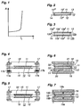
- Figure 1 shows the resistivity R as a function of the temperature T for an electrically conductive polymer composition which is included in the PTC element according to the present invention.
- T t is the transition temperature, at which the polymer composition changes from a low resistance to a high resistance state.
- the PTC element according to Figure 2 comprises a centrally arranged body 10 of an electrically conductive polymer composition with a positive temperature coefficient, for example consisting of 67 per cent by volume polyethylene (e.g. LUPOLEN 6031 M from BASF, Germany) and 33 per cent by volume carbon black (e.g. N 550 from Degussa AG, Germany), in the form of a rectangular 1 mm thick plate as well as two electrodes 11 and 12 with associated terminals 13 and 14, respectively, arranged at the parallel large end surfaces 10' and 10'' of the body (the flat sides of the plate).
- the electrode 11 consists of an 0.5 mm thick plate of nickel with an even surface structure on both sides. On the outside, the plate is coated with a thin layer of copper.
- the plate makes free contact with the body, that is, makes contact only by abutting the body, and thus not being fixed to the body.
- the electrode 12 consists of an 0.3 mm thick copper foil which on the side facing the body 10 is coated with an 0.1 mm thick layer of copper with uneven surface structure, applied by plasma spraying.
- the electrode 12 is fixed to the polymer by being pressed against the body 10, when the body has been heated, so that the polymer material in liquid state may penetrate into irregularities on the inwardly-facing side of the electrode.
- the device according to Figure 3 includes two bodies, 10a and 10b, of the same electrically conductive polymer composition as that in the body 10 in Figure 1, in the form of 1 mm thick rectangular plates with the parallel surfaces 10a', 10a'' and 10b', 10b'', respectively. These plates make electrical contact with each other only by abutment without being fused or otherwise fixed to each other, that is, they make free contact with each other.
- the electrodes 11 and 12 may be of the same kind as the electrodes 11 and 12 in Figure 1. However, the electrode 11 may also be of the same kind as the electrode 12 and, like this electrode, be fixed to the body 10a.
- the bodies 10a and 10b may be of different electrically conductive polymer compositions and have different resistivities to modify the properties of the PTC element.
- the device may also be modified so as to comprise more than two bodies (10a and 10b) of conductive polymer composition with the same or a different resistivity. If the electrodes are fixed to adjacent bodies of electrically conductive polymer composition, at least one of the bodies must make free contact with another one of the bodies. If one or both of the electrodes make free contact with an adjacent body of electrically conductive polymer composition, all the polymer bodies may be fixed to each other, for example by fusion.
- FIG 4 illustrates a device according to the invention in which a PTC element according to Figure 2 is arranged in a pressure device comprising two plates 15, 16, which are parallel to the large parallel surfaces of the body 10 (the flat sides of the plate 10) and to the electrodes 11 and 12.
- the terminals 13 and 14 are not shown in the figure.
- the plates are of electrically insulating material, for example resin reinforced with glass fibre.
- the pressure against the electrodes and against the large surfaces of the body 10 is brought about by tightening a number of bolts 17.
- stiff springs 17b are arranged which are not completely compressed when the PTC element is pressurized and prepared for normal operation. In case of a short circuit, the springs may therefore be further compressed, which permits the electrode 11 to be separated from the body 10.
- the device according to Figure 5 differs from the device according to Figure 4 in that the springs 17b are not included and in that a 1 mm thick mat 30 of rubber is arranged between the electrode 11 and the plate 15. Such a mat of rubber may possibly be arranged between the electrode 12 and the plate 16 as well.
- a PTC element according to Figure 3 may be arranged, in an analogous manner, in the devices according to Figures 4 and 5.
- a PTC element according to Figure 2 or 3 is provided with plates 32, 33, arranged outside the electrodes 11,12, of copper or other high conductivity material between two opposite yokes 18 and 19, respectively, of iron or other ferromagnetic material.
- the iron yokes are U-shaped with a base 18a and 19a, respectively, of flat shape and with short legs 18b and 19b, respectively. Alternatively, only plates corresponding to the base 18a and 19a, respectively, may be used.
- two PTC element of the kind shown in Figure 2 are arranged one above the other with an intermediate mat 30a of rubber.
- the two electrodes 11 are parallel-connected as are the two electrodes 12.
- the PTC element can be subjected to pressure in a manner analogous to that of the PTC elements according to Figure 2 in the devices according to Figures 4 and 5 with the two electrodes 12 making contact with the plates 15 and 16.
- no advantage is gained by utilizing springs 17b according to Figure 4 or a rubber mat 30 according to Figure 5.
- the PTC element according to Figure 8 is formed without a rubber mat 30a, that is, with the two electrodes 11 making contact with each other or replaced by one single electrode which on both sides makes contact with bodies 10 of electrically conductive polymer composition and this PTC element is arranged in the pressure devices according to Figures 4 and 5, it is an advantage to retain the springs 17b and the rubber mat 30.
- a PTC element according to Figure 3 may be used in the cases describes with reference to Figure 8.
- a PTC element according to Figure 8 has particularly good current limiting properties.
- the PTC element according to Figure 9 is of the same kind as that shown in Figure 2 but is provided with a casing 35 of insulating material, preferably of polyethylene, which is the same polymer material as included in the body 10 of electrically conductive polymer composition.
- the casing 35 surrounds the surfaces 10''' on the body 10 which are exposed between the electrodes 11 and 12, which, as explained above, increases the dielectric strength of the PTC element.
- the PTC element according to Figure 9 may be arranged in the same way as the PTC element according to Figure 2 in the pressure devices according to Figures 4 and 5.
- a PTC element according to Figure 3 may be used, in an analogous manner, in a PTC element according to Figure 9, the casing surrounding the surfaces 10a''' and 10b''' on the bodies 10a and 10b.
- the casing 35 of insulating material may be applied around the body 10 or the bodies 10a and 10b by applying a ring of insulating material around the body 10 or the bodies 10a and 10b in a tool suitable therefore and be brought to fuse together, by heating, with the edges on the body 10 or the bodies 10a and 10b.
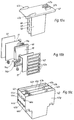
- the device according to Figures 10a to 10c and 11 comprises three identical PTC elements, one of which being shown with the parts separated in Figure 10b.
- the body 10 of electrically conductive polymer composition for example of the same kind as in Figure 2, is arranged in a plastic frame 40 which extends around the body.
- the two electrodes 11 and 12 consist of 1 mm thick silver-plated plates of copper, which make free contact with the body 10, that is, only by abutting it, and thus not being fixed to it.
- Each electrode is provided with alternative conductor terminals 13a and 14a for cable connection and 13b (not shown) and 14b for connection to a bar, respectively.
- a package comprising the plates 41 and 42 and electrodes 11 and 12 arranged therebetween and with an intermediate body 10 of conducting polymer composition is arranged in each one of three compartments 43a, 43b, and 43c in an apparatus housing 43 with two partitions 43d and 43e forming the compartments.
- the partitions are parallel to two opposite, parallel walls 43f and 43g in the apparatus housing.
- the apparatus housing is provided with hollows 44a and 44b for alternative connection of a conductor to the attachment 14a or 14b in the compartment 43a, with hollows 45a and 45b for alternative connection of a conductor to the attachment 14a or 14b in the compartment 43b, and with hollows 46a and 46b for alternative connection of a conductor to the attachments 14a or 14b on an electrode 12 in the compartment 43c.
- hollows 44a and 44b for alternative connection of a conductor to the attachment 14a or 14b in the compartment 43a
- hollows 45a and 45b for alternative connection of a conductor to the attachment 14a or 14b in the compartment 43b
- hollows 46a and 46b for alternative connection of a conductor to the attachments 14a or 14b on an electrode 12 in the compartment 43c.
- On the opposite, not visible wall of the apparatus housing there are corresponding recesses for connection of conductors to the attachments 13a and 13b on each electrode 11.
- the pressure between the electrode 11 and 12 and the body 10 in each one of the packages in the compartments 43a, 43b and 43c is brought about by applying a lid 47 with wedge-shaped plates 48, 49 and 50, fixed to the lid, on the apparatus housing.
- a wedge-shaped plate is thereby inserted into each one of the compartments 43a, 43b and 43c adjacent a plate 41 located therein.
- the lid is provided with mechanical attachments 47a, 47b, 47c and 47d for mounting.
- the apparatus housing is provided with plane-parallel reinforcing walls 51 and 52 on the pressure-absorbing sides.
- the device according to Figures 10a, 10b, 10c and 11 is intended to be connected into a three-phase cable with a PTC element connected into each of the three phase conductors.
- the apparatus housing 43 with outer walls 43f and 43g, reinforcing walls 51 and 52, lid 47 and wedge-shaped plates 41, 48, 49 and 50 are all manufactured form an electrical insulating material, for example a polyamide, to which a filler, for example in the form of short glass-fibres, has been added.
- the PTC element according to Figure 12 comprises a tubular body 10 of an electrically conductive polymer composition with a positive temperature coefficient, for example of the same composition as that used in the body 10 in Figure 2.
- the interior cylindrical envelope surface is designated 10' and the exterior also cylindrical envelope surface is designated 10''.
- each one of the envelope surfaces forms a circle.
- the wall thickness of the tubular body amounts to at least 1 mm.
- the PTC element also has two electrodes 11 and 12 which are arranged in contact with the envelope surfaces 10' and 10'' and concentric therewith. The electrodes are provided with terminals 13 and 14, respectively.
- the electrode 11 consists of an 0.5 mm thick tube of nickel with an even surface structure on both sides.
- the tube On the outside the tube is coated with a thin layer of copper.
- the tube is slitted in the longitudinal direction so that one edge at the slit is able to slide over the other.
- the electrode 11 makes free contact with the body 10, that is, makes contact only by abutting the body along the envelope surface 10' under pressure, without being fixed to the body.
- the electrode 12 consists of an 0.3 mm thick copper foil which on the side facing the body 10 is coated with an 0.1 mm thick layer of copper with an uneven surface structure, applied by plasma spraying.
- the electrode 12 is fixed to the polymer by being pressed against the body 10, after the body has been heated so that the polymer material in liquid state may penetrate into irregularities in the inwardly-facing side of the electrode.
- a body 31 which is expansible in a direction perpendicular to the envelope surface 10' and the electrode 11.
- a counter-support 32 for example in the form of a tube of resin reinforced with fibre-glass, which is manufactured in situ, for example by applying the glass-fibre material and the resin in uncured state onto the electrode 12, and thereafter curing the resin.
- the expansible body 31 consists in the exemplified case of a tubular body 31a of rubber or other elastic material, which by means of a bolt 31b, arranged centrally in the body, with a bolt head 31c and a nut 31d and with washers 31e and 31f arranged at the end surfaces, inside the bolt head and the nut, may be brought to expand while achieving a desired pressure against the electrode 11.
- the electrode 12 may be formed as a tube with sufficient thickness to serve itself as a counter-support, such as in the form of a tube of copper which has been drawn down, on the spot, to the intended dimension to make contact directly with the envelope surface 10'' on the body 10.
- both electrodes of the PTC element are adapted to make free contact, under pressure, with the envelope surfaces 10' and 10'' on the body 10.
- a copper tube may alternatively be adapted to serve only as a counter-support and then to make contact with the electrode 12.
- the electrode 12 may, instead of being fixed to the body 10, be adapted to make free contact with the body 10.
- a sleeve of memory metal may be used as a separate counter-support or both as a counter-support and an electrode, the sleeve in expanded state being arranged on the spot around the PTC element and thereafter brought to resume its smaller dimension before the expansion.
- the expansible body 31 consists of a body of metallic material, it may be suitable or necessary to arrange a layer of rubber or other electrically insulating material between the expansible body and the electrode 11.
- the device according to Figure 13 includes two bodies 10a and 10b, of the same electrically conductive polymer composition as that in the body 10 in Figure 12, in the form of concentric tubes with a wall thickness of 1 mm.
- the concentric envelope surfaces are designated 10a', 10a'' and 10b', 10b'', respectively.
- the two bodies 10a and 10b make free contact with each other, that is, make contact only by abutment under pressure, and thus not by being fused or otherwise fixed to each other.
- the electrodes 11 and 12 may be of the same kind as the electrodes 11 and 12 in Figure 12. However, the electrode 11 may also be of the same kind as the electrode 12 in the first exemplified case, when this is fixed to the body of polymer composition, and thus be fixed to the body 10a.
- the bodies 10a and 10b may be of different electrically conductive polymer composition and have different resistivity to modify the properties of the PTC element.
- the device can also be modified so as to contain more than two concentric bodies (10a and 10b) of conductive polymer composition with the same or with different resistivity. If the electrodes are fixed to adjacent bodies of electrically conductive polymer composition, at least one of the bodies must make free contact with another one of the bodies. If one or both of the electrodes make free contact with an adjacent body of electrically conductive polymer composition, all polymer bodies may be fixed to one another, for example by fusion.
- the device 31 with its parts for maintaining the electrodes 11 and 12 and the bodies 10a and 10b pressed against each other in the PTC element according to Figure 13 is in the exemplified case the same as that in the PTC element according to Figure 12.
- the PTC element according to Figure 14 differs from the PTC element according to Figure 12 in that a 1 mm thick layer 33 of rubber or other elastic material is arranged between the electrode 12 and the counter-support 32 to increase the elasticity of the pressure-exerting parts.
- the electrode 12 instead of being fixed to the body 10, the electrode 12 may make free contact with the body, that is, only by abutting the body along the envelope surface 10''.
- the electrode consists of a solid wire of copper or nickel with a thin coating of nickel.
- the electrode 11 makes free contact with the body 10, that is, only by abutting the body along the envelope surface 10'.
- the body 10 and the electrode 12 are of the same kind as the corresponding elements in the device according to Figure 12.
- a drawing or clamping device 34 which, for example, may consist of a plate 34a arranged around the electrode 12 with an intermediate elastic insulating layer (not shown), tha plate being provided with overlapping edges in the axial direction of the body 10, so that the diameter of the tubular body formed by the plate can be reduced by tightening a screw device 34b, in a manner analogous to that of a hose clamp, or by compressing two jaws with an internally semicylindrical shape in a direction perpendicular to the envelope surfaces 10'and 10'' of the body 10.
- the electrode 11 itself serves as a counter-support.
- an electrode 11 in the form of a solid wire in accordance with Figure 15, to use an electrode 11 in the form of a layer of the kind illustrated in Figures 12 to 14 and a counter-support arranged inside such an electrode in the form of a rigid body or an elastic device, for example of the kind designated 31 in Figure 12 to 14.
- the PTC element according to Figure 16 differs from the PTC element according to Figure 15 in that a 1 mm thick layer 33 of rubber or other elastic material is arranged between the electrode 12 and the plate 34a to increase the capacity of the pressure-exerting parts to be elastic.
- a sleeve of memory metal it is possible to use a sleeve of memory metal, the sleeve of memory metal in expanded state being arranged in place around the PTC element and thereafter being brought to assume a smaller diameter.
- Such a sleeve may at the same time serve as an electrode in the case illustrated in Figure 15.
- FIG 17 exemplifies the use of the PTC element according to the invention as overcurrent and short-circuit protective device in an electric circuit 26 comprising a motor 25.
- the PTC element 22 for example of the kind shown in Figure 4, 5, 12 or 13, is series-connected to a contact device 23.
- an excitation coil 24 which is included in a fast magnetic tripping device for the contact device.
- the tripping device is adapted to influence the contact device for opening this at an overcurrent.
Landscapes
- Engineering & Computer Science (AREA)
- Microelectronics & Electronic Packaging (AREA)
- Chemical & Material Sciences (AREA)
- Dispersion Chemistry (AREA)
- Ceramic Engineering (AREA)
- Physics & Mathematics (AREA)
- Electromagnetism (AREA)
- Thermistors And Varistors (AREA)
- Inorganic Insulating Materials (AREA)
- Amplifiers (AREA)
Applications Claiming Priority (4)
| Application Number | Priority Date | Filing Date | Title |
|---|---|---|---|
| SE9003448 | 1990-10-30 | ||
| SE9003448A SE9003448L (en) | 1990-10-30 | 1990-10-30 | PTC element for overcurrent protection - has surface of body of polymer composition that makes free contact with each other or with associated electrode |
| SE9003814A SE467513B (sv) | 1990-11-30 | 1990-11-30 | Ptc-element |
| SE9003814 | 1990-11-30 |
Publications (2)
| Publication Number | Publication Date |
|---|---|
| EP0487920A1 true EP0487920A1 (de) | 1992-06-03 |
| EP0487920B1 EP0487920B1 (de) | 1996-09-18 |
Family
ID=26660895
Family Applications (1)
| Application Number | Title | Priority Date | Filing Date |
|---|---|---|---|
| EP91118512A Expired - Lifetime EP0487920B1 (de) | 1990-10-30 | 1991-10-30 | Komponente mit positiven Temperaturkoeffizienten |
Country Status (7)
| Country | Link |
|---|---|
| US (1) | US5382938A (de) |
| EP (1) | EP0487920B1 (de) |
| JP (1) | JPH04266001A (de) |
| AT (1) | ATE143169T1 (de) |
| CA (1) | CA2054487C (de) |
| DE (1) | DE69122216T2 (de) |
| ES (1) | ES2094180T3 (de) |
Cited By (12)
| Publication number | Priority date | Publication date | Assignee | Title |
|---|---|---|---|---|
| WO1996002924A1 (en) * | 1994-07-14 | 1996-02-01 | Surgx Corporation | Single and multi-layer variable voltage protection devices and methods of making same |
| FR2733353A1 (fr) * | 1995-04-18 | 1996-10-25 | Gec Alsthom T & D Sa | Limiteur de courant de court-circuit pour reseau a haute tension |
| US5614881A (en) * | 1995-08-11 | 1997-03-25 | General Electric Company | Current limiting device |
| US5644283A (en) * | 1992-08-26 | 1997-07-01 | Siemens Aktiengesellschaft | Variable high-current resistor, especially for use as protective element in power switching applications & circuit making use of high-current resistor |
| DE19636932C1 (de) * | 1996-09-11 | 1998-01-02 | Siemens Ag | Relais mit Überlastschutz |
| US5793278A (en) * | 1993-09-09 | 1998-08-11 | Siemens Aktiengesellschaft | Limiter for current limiting |
| US5859579A (en) * | 1993-07-26 | 1999-01-12 | Siemens Aktiengesellschaft | Current--limiting switch |
| WO1999010903A1 (en) * | 1997-08-25 | 1999-03-04 | Square D Company | Current limiting circuit breakers with ptc (positive temperature coefficient resistivity) elements and arc extinguishing capabilities |
| ES2142263A1 (es) * | 1997-02-10 | 2000-04-01 | Gen Electric | Unidad de disyuntor de supresion de corrientes para proteccion de motores de induccion. |
| EP1213728A3 (de) * | 2000-11-27 | 2005-10-26 | Eaton Corporation | Strombegrenzungseinrichtung |
| EP1921637A3 (de) * | 2006-11-10 | 2009-01-14 | Epcos Ag | Elektrische Baugruppe mit PTC-Widerstandselementen |
| US7928828B2 (en) | 2006-11-10 | 2011-04-19 | Epcos Ag | Electrical assembly with PTC resistor elements |
Families Citing this family (81)
| Publication number | Priority date | Publication date | Assignee | Title |
|---|---|---|---|---|
| JP3605115B2 (ja) * | 1994-06-08 | 2004-12-22 | レイケム・コーポレイション | 導電性ポリマーを含有する電気デバイス |
| JPH07335408A (ja) * | 1994-06-10 | 1995-12-22 | Murata Mfg Co Ltd | 発熱電子部品 |
| KR100369681B1 (ko) * | 1994-07-14 | 2003-04-11 | 서직스 코퍼레이션 | 가변전압보호구조및그제조방법 |
| SE515262C2 (sv) * | 1995-02-16 | 2001-07-09 | Abb Research Ltd | Anordning för strömbegränsning och skydd mot kortslutningsströmmar i en elektrisk anläggning |
| AU5678496A (en) * | 1995-05-10 | 1996-11-29 | Littelfuse, Inc. | Ptc circuit protection device and manufacturing process for same |
| US5663702A (en) * | 1995-06-07 | 1997-09-02 | Littelfuse, Inc. | PTC electrical device having fuse link in series and metallized ceramic electrodes |
| ATE302465T1 (de) * | 1995-06-07 | 2005-09-15 | Tyco Electronics Corp | Elektrische vorrichtung mit ptc-verhalten |
| US6023403A (en) | 1996-05-03 | 2000-02-08 | Littlefuse, Inc. | Surface mountable electrical device comprising a PTC and fusible element |
| US5939968A (en) * | 1996-06-19 | 1999-08-17 | Littelfuse, Inc. | Electrical apparatus for overcurrent protection of electrical circuits |
| US6215388B1 (en) | 1996-09-27 | 2001-04-10 | Therm-Q-Disc, Incorporated | Parallel connected PTC elements |
| US5929744A (en) * | 1997-02-18 | 1999-07-27 | General Electric Company | Current limiting device with at least one flexible electrode |
| US6535103B1 (en) | 1997-03-04 | 2003-03-18 | General Electric Company | Current limiting arrangement and method |
| US5977861A (en) * | 1997-03-05 | 1999-11-02 | General Electric Company | Current limiting device with grooved electrode structure |
| US6606011B2 (en) | 1998-04-07 | 2003-08-12 | X2Y Attenuators, Llc | Energy conditioning circuit assembly |
| US7274549B2 (en) | 2000-12-15 | 2007-09-25 | X2Y Attenuators, Llc | Energy pathway arrangements for energy conditioning |
| US7336467B2 (en) | 2000-10-17 | 2008-02-26 | X2Y Attenuators, Llc | Energy pathway arrangement |
| US6603646B2 (en) * | 1997-04-08 | 2003-08-05 | X2Y Attenuators, Llc | Multi-functional energy conditioner |
| US7110235B2 (en) | 1997-04-08 | 2006-09-19 | Xzy Altenuators, Llc | Arrangement for energy conditioning |
| US6650525B2 (en) | 1997-04-08 | 2003-11-18 | X2Y Attenuators, Llc | Component carrier |
| US7336468B2 (en) | 1997-04-08 | 2008-02-26 | X2Y Attenuators, Llc | Arrangement for energy conditioning |
| US6954346B2 (en) | 1997-04-08 | 2005-10-11 | Xzy Attenuators, Llc | Filter assembly |
| US7301748B2 (en) | 1997-04-08 | 2007-11-27 | Anthony Anthony A | Universal energy conditioning interposer with circuit architecture |
| US9054094B2 (en) | 1997-04-08 | 2015-06-09 | X2Y Attenuators, Llc | Energy conditioning circuit arrangement for integrated circuit |
| US7106570B2 (en) | 1997-04-08 | 2006-09-12 | Xzy Altenuators, Llc | Pathway arrangement |
| US6018448A (en) | 1997-04-08 | 2000-01-25 | X2Y Attenuators, L.L.C. | Paired multi-layered dielectric independent passive component architecture resulting in differential and common mode filtering with surge protection in one integrated package |
| US20030161086A1 (en) | 2000-07-18 | 2003-08-28 | X2Y Attenuators, Llc | Paired multi-layered dielectric independent passive component architecture resulting in differential and common mode filtering with surge protection in one integrated package |
| US7042703B2 (en) | 2000-03-22 | 2006-05-09 | X2Y Attenuators, Llc | Energy conditioning structure |
| US6894884B2 (en) | 1997-04-08 | 2005-05-17 | Xzy Attenuators, Llc | Offset pathway arrangements for energy conditioning |
| US7110227B2 (en) | 1997-04-08 | 2006-09-19 | X2Y Attenuators, Llc | Universial energy conditioning interposer with circuit architecture |
| US7321485B2 (en) | 1997-04-08 | 2008-01-22 | X2Y Attenuators, Llc | Arrangement for energy conditioning |
| US6191681B1 (en) | 1997-07-21 | 2001-02-20 | General Electric Company | Current limiting device with electrically conductive composite and method of manufacturing the electrically conductive composite |
| US6104587A (en) * | 1997-07-25 | 2000-08-15 | Banich; Ann | Electrical device comprising a conductive polymer |
| US5886860A (en) * | 1997-08-25 | 1999-03-23 | Square D Company | Circuit breakers with PTC (Positive Temperature Coefficient resistivity |
| US5933311A (en) * | 1998-04-02 | 1999-08-03 | Square D Company | Circuit breaker including positive temperature coefficient resistivity elements having a reduced tolerance |
| IL121703A0 (en) * | 1997-09-03 | 1998-02-22 | Body Heat Ltd | Fabrication of PTC heating devices |
| EP1026705A4 (de) * | 1997-10-03 | 2008-03-05 | Tyco Electronics Raychem Kk | Elektrische zusammensetzung und vorrichtung |
| US6373372B1 (en) | 1997-11-24 | 2002-04-16 | General Electric Company | Current limiting device with conductive composite material and method of manufacturing the conductive composite material and the current limiting device |
| US6128168A (en) | 1998-01-14 | 2000-10-03 | General Electric Company | Circuit breaker with improved arc interruption function |
| US6282072B1 (en) | 1998-02-24 | 2001-08-28 | Littelfuse, Inc. | Electrical devices having a polymer PTC array |
| US6020802A (en) * | 1998-04-02 | 2000-02-01 | Square D Company | Circuit breaker including two magnetic coils and a positive temperature coefficient resistivity element |
| DE69937677T2 (de) | 1998-04-07 | 2008-11-20 | X2Y Attenuators, L.L.C. | Bauelementeträger |
| US7427816B2 (en) | 1998-04-07 | 2008-09-23 | X2Y Attenuators, Llc | Component carrier |
| US6606023B2 (en) | 1998-04-14 | 2003-08-12 | Tyco Electronics Corporation | Electrical devices |
| US6124780A (en) * | 1998-05-20 | 2000-09-26 | General Electric Company | Current limiting device and materials for a current limiting device |
| US6290879B1 (en) | 1998-05-20 | 2001-09-18 | General Electric Company | Current limiting device and materials for a current limiting device |
| US6133820A (en) * | 1998-08-12 | 2000-10-17 | General Electric Company | Current limiting device having a web structure |
| DE19842008A1 (de) * | 1998-09-15 | 2000-03-16 | Moeller Gmbh | Kontaktanordnung elektrisch leitfähiger Polymere |
| DE19842006A1 (de) * | 1998-09-15 | 2000-03-16 | Moeller Gmbh | Kontaktanordnung elektrisch leitfähiger Polymere |
| US6582647B1 (en) | 1998-10-01 | 2003-06-24 | Littelfuse, Inc. | Method for heat treating PTC devices |
| US5963121A (en) * | 1998-11-11 | 1999-10-05 | Ferro Corporation | Resettable fuse |
| US6157528A (en) | 1999-01-28 | 2000-12-05 | X2Y Attenuators, L.L.C. | Polymer fuse and filter apparatus |
| US6144540A (en) * | 1999-03-09 | 2000-11-07 | General Electric Company | Current suppressing circuit breaker unit for inductive motor protection |
| US6157286A (en) * | 1999-04-05 | 2000-12-05 | General Electric Company | High voltage current limiting device |
| US6854176B2 (en) * | 1999-09-14 | 2005-02-15 | Tyco Electronics Corporation | Process for manufacturing a composite polymeric circuit protection device |
| US6640420B1 (en) | 1999-09-14 | 2003-11-04 | Tyco Electronics Corporation | Process for manufacturing a composite polymeric circuit protection device |
| US6323751B1 (en) | 1999-11-19 | 2001-11-27 | General Electric Company | Current limiter device with an electrically conductive composite material and method of manufacturing |
| US6429533B1 (en) * | 1999-11-23 | 2002-08-06 | Bourns Inc. | Conductive polymer device and method of manufacturing same |
| JP2003520420A (ja) * | 2000-01-11 | 2003-07-02 | タイコ・エレクトロニクス・コーポレイション | 電気デバイス |
| US6388553B1 (en) | 2000-03-02 | 2002-05-14 | Eaton Corproation | Conductive polymer current-limiting fuse |
| US7113383B2 (en) | 2000-04-28 | 2006-09-26 | X2Y Attenuators, Llc | Predetermined symmetrically balanced amalgam with complementary paired portions comprising shielding electrodes and shielded electrodes and other predetermined element portions for symmetrically balanced and complementary energy portion conditioning |
| US7262949B2 (en) | 2000-08-15 | 2007-08-28 | X2Y Attenuators, Llc | Electrode arrangement for circuit energy conditioning |
| US6628498B2 (en) | 2000-08-28 | 2003-09-30 | Steven J. Whitney | Integrated electrostatic discharge and overcurrent device |
| US7193831B2 (en) * | 2000-10-17 | 2007-03-20 | X2Y Attenuators, Llc | Energy pathway arrangement |
| US7433168B2 (en) * | 2000-10-17 | 2008-10-07 | X2Y Attenuators, Llc | Amalgam of shielding and shielded energy pathways and other elements for single or multiple circuitries with common reference node |
| US6411191B1 (en) | 2000-10-24 | 2002-06-25 | Eaton Corporation | Current-limiting device employing a non-uniform pressure distribution between one or more electrodes and a current-limiting material |
| JP4030871B2 (ja) * | 2000-12-12 | 2008-01-09 | 独立行政法人科学技術振興機構 | 電気自動車の操舵機構 |
| US6798331B2 (en) * | 2001-02-08 | 2004-09-28 | Qortek, Inc. | Current control device |
| US7180718B2 (en) * | 2003-01-31 | 2007-02-20 | X2Y Attenuators, Llc | Shielded energy conditioner |
| EP1629582A2 (de) | 2003-05-29 | 2006-03-01 | X2Y Attenuators, L.L.C. | Verbinderbezogene strukturen mit einer energie-aufbereitungseinrichtung |
| US7515032B2 (en) * | 2003-07-02 | 2009-04-07 | Tyco Electronics Raychem K.K. | Combined PTC device |
| EP1698033A4 (de) | 2003-12-22 | 2010-07-21 | X2Y Attenuators Llc | Intern abgeschirmte energieaufbereitungsvorrichtung |
| WO2006093831A2 (en) | 2005-03-01 | 2006-09-08 | X2Y Attenuators, Llc | Energy conditioner with tied through electrodes |
| US7630188B2 (en) | 2005-03-01 | 2009-12-08 | X2Y Attenuators, Llc | Conditioner with coplanar conductors |
| US7586728B2 (en) | 2005-03-14 | 2009-09-08 | X2Y Attenuators, Llc | Conditioner with coplanar conductors |
| EP1991996A1 (de) | 2006-03-07 | 2008-11-19 | X2Y Attenuators, L.L.C. | Energiekonditionierungsstrukturen |
| US20090027821A1 (en) * | 2007-07-26 | 2009-01-29 | Littelfuse, Inc. | Integrated thermistor and metallic element device and method |
| DE102011077922B4 (de) * | 2011-06-21 | 2024-10-10 | Mahle International Gmbh | Wärmeübertrager |
| CN106165037B (zh) * | 2014-04-08 | 2019-03-22 | 西门子公司 | 用于保护电部件免受过电流损坏的方法 |
| JP6305816B2 (ja) * | 2014-04-11 | 2018-04-04 | Koa株式会社 | 金属板抵抗器 |
| CN110364321B (zh) * | 2018-03-26 | 2021-07-13 | 国巨电子(中国)有限公司 | 分流电阻器的制造方法 |
| DE102019108435B4 (de) * | 2019-04-01 | 2025-02-06 | Borgwarner Ludwigsburg Gmbh | Verfahren zum Herstellen eines Heizstabs |
Citations (3)
| Publication number | Priority date | Publication date | Assignee | Title |
|---|---|---|---|---|
| US2978665A (en) * | 1956-07-11 | 1961-04-04 | Antioch College | Regulator device for electric current |
| EP0026456A2 (de) * | 1979-09-28 | 1981-04-08 | Siemens Aktiengesellschaft | Kaltleiter-Heizeinrichtung |
| EP0240447A2 (de) * | 1986-04-04 | 1987-10-07 | Emerson Electric Co. | Thermische Schutze für PTC-Elemente |
Family Cites Families (5)
| Publication number | Priority date | Publication date | Assignee | Title |
|---|---|---|---|---|
| US3878501A (en) * | 1974-01-02 | 1975-04-15 | Sprague Electric Co | Asymmetrical dual PTCR package for motor start system |
| US3914727A (en) * | 1974-01-02 | 1975-10-21 | Sprague Electric Co | Positive-temperature-coefficient-resistor package |
| GB2090710B (en) * | 1980-12-26 | 1984-10-03 | Matsushita Electric Industrial Co Ltd | Thermistor heating device |
| JPH01143203A (ja) * | 1987-11-27 | 1989-06-05 | Murata Mfg Co Ltd | 有機正特性サーミスタ |
| JPH01220403A (ja) * | 1988-02-26 | 1989-09-04 | Murata Mfg Co Ltd | ケース内蔵型の正特性サーミスタ |
-
1991
- 1991-10-25 US US07/783,118 patent/US5382938A/en not_active Expired - Lifetime
- 1991-10-29 CA CA002054487A patent/CA2054487C/en not_active Expired - Fee Related
- 1991-10-29 JP JP3283174A patent/JPH04266001A/ja active Pending
- 1991-10-30 AT AT91118512T patent/ATE143169T1/de not_active IP Right Cessation
- 1991-10-30 DE DE69122216T patent/DE69122216T2/de not_active Expired - Fee Related
- 1991-10-30 EP EP91118512A patent/EP0487920B1/de not_active Expired - Lifetime
- 1991-10-30 ES ES91118512T patent/ES2094180T3/es not_active Expired - Lifetime
Patent Citations (3)
| Publication number | Priority date | Publication date | Assignee | Title |
|---|---|---|---|---|
| US2978665A (en) * | 1956-07-11 | 1961-04-04 | Antioch College | Regulator device for electric current |
| EP0026456A2 (de) * | 1979-09-28 | 1981-04-08 | Siemens Aktiengesellschaft | Kaltleiter-Heizeinrichtung |
| EP0240447A2 (de) * | 1986-04-04 | 1987-10-07 | Emerson Electric Co. | Thermische Schutze für PTC-Elemente |
Cited By (17)
| Publication number | Priority date | Publication date | Assignee | Title |
|---|---|---|---|---|
| US5644283A (en) * | 1992-08-26 | 1997-07-01 | Siemens Aktiengesellschaft | Variable high-current resistor, especially for use as protective element in power switching applications & circuit making use of high-current resistor |
| US5859579A (en) * | 1993-07-26 | 1999-01-12 | Siemens Aktiengesellschaft | Current--limiting switch |
| US5793278A (en) * | 1993-09-09 | 1998-08-11 | Siemens Aktiengesellschaft | Limiter for current limiting |
| EP1233427A1 (de) * | 1994-07-14 | 2002-08-21 | Surgx Corporation | Einschicht- und Mehrschicht-Schutzvorrichtungen gegen veränderliche Spannung |
| US5807509A (en) * | 1994-07-14 | 1998-09-15 | Surgx Corporation | Single and multi layer variable voltage protection devices and method of making same |
| WO1996002924A1 (en) * | 1994-07-14 | 1996-02-01 | Surgx Corporation | Single and multi-layer variable voltage protection devices and methods of making same |
| FR2733353A1 (fr) * | 1995-04-18 | 1996-10-25 | Gec Alsthom T & D Sa | Limiteur de courant de court-circuit pour reseau a haute tension |
| US5614881A (en) * | 1995-08-11 | 1997-03-25 | General Electric Company | Current limiting device |
| DE19636932C1 (de) * | 1996-09-11 | 1998-01-02 | Siemens Ag | Relais mit Überlastschutz |
| US5889453A (en) * | 1996-09-11 | 1999-03-30 | Siemens Aktiengesellschaft | Relay with overload protection |
| ES2142263A1 (es) * | 1997-02-10 | 2000-04-01 | Gen Electric | Unidad de disyuntor de supresion de corrientes para proteccion de motores de induccion. |
| WO1999010903A1 (en) * | 1997-08-25 | 1999-03-04 | Square D Company | Current limiting circuit breakers with ptc (positive temperature coefficient resistivity) elements and arc extinguishing capabilities |
| EP1213728A3 (de) * | 2000-11-27 | 2005-10-26 | Eaton Corporation | Strombegrenzungseinrichtung |
| EP1921637A3 (de) * | 2006-11-10 | 2009-01-14 | Epcos Ag | Elektrische Baugruppe mit PTC-Widerstandselementen |
| US7928828B2 (en) | 2006-11-10 | 2011-04-19 | Epcos Ag | Electrical assembly with PTC resistor elements |
| CN101178960B (zh) * | 2006-11-10 | 2011-05-25 | 埃普科斯股份有限公司 | 具有ptc电阻元件的电气部件 |
| US7986214B2 (en) | 2006-11-10 | 2011-07-26 | Epcos Ag | Electrical assembly with PTC resistor elements |
Also Published As
| Publication number | Publication date |
|---|---|
| US5382938A (en) | 1995-01-17 |
| CA2054487C (en) | 1998-02-17 |
| JPH04266001A (ja) | 1992-09-22 |
| CA2054487A1 (en) | 1992-05-01 |
| DE69122216T2 (de) | 1997-04-30 |
| DE69122216D1 (de) | 1996-10-24 |
| ATE143169T1 (de) | 1996-10-15 |
| ES2094180T3 (es) | 1997-01-16 |
| EP0487920B1 (de) | 1996-09-18 |
Similar Documents
| Publication | Publication Date | Title |
|---|---|---|
| US5382938A (en) | PTC element | |
| US5886324A (en) | Electrode attachment for high power current limiting polymer devices | |
| US6005470A (en) | Arc-quenching filler for high voltage current limiting fuses and circuit interrupters | |
| CA1111881A (en) | Electric fuse having folded fusible element and heat dams | |
| EP0363746B2 (de) | Überstromschutzeinrichtung für elektrische Netzwerke und Apparate | |
| US20030001716A1 (en) | Fusible link | |
| EP0537486B1 (de) | Überspannungsableiteranordnung | |
| US4298900A (en) | Overvoltage protective device | |
| US6388553B1 (en) | Conductive polymer current-limiting fuse | |
| US20020101323A1 (en) | High-voltage current-limiting fuse | |
| JPH08505731A (ja) | 保護装置 | |
| US20020125982A1 (en) | Surface mount electrical device with multiple ptc elements | |
| KR20010075545A (ko) | 전도성 폴리머 ptc 배터리 보호 장치 및 그 제조 방법 | |
| US6157286A (en) | High voltage current limiting device | |
| EP0607269A1 (de) | Überstrom und kurzschlussschutzeinrichtung für elektrische anlage | |
| JPH07505757A (ja) | 過負荷保護システム | |
| EP0092737B1 (de) | Blitzableiter | |
| US4638285A (en) | Surge suppressing resistor for a disconnect switch | |
| US5537286A (en) | Method of preparing planar PTC circuit protection devices | |
| CA1141427A (en) | Protected electrical inductive apparatus | |
| CA2146037C (en) | Current-limiting fuse and housing arrangement | |
| CN115938891A (zh) | 一种高压新能源柔性熔断器及其制备方法 | |
| CA2292935A1 (en) | Current limiting device with reduced resistance | |
| DE69309949T2 (de) | Vorrichtung zum schutz gegen überstrome | |
| KR100729011B1 (ko) | Ptc 한류 모듈 및 이를 이용한 3상 일괄형 한류기 |
Legal Events
| Date | Code | Title | Description |
|---|---|---|---|
| PUAI | Public reference made under article 153(3) epc to a published international application that has entered the european phase |
Free format text: ORIGINAL CODE: 0009012 |
|
| AK | Designated contracting states |
Kind code of ref document: A1 Designated state(s): AT BE CH DE ES FR GB IT LI NL SE |
|
| 17P | Request for examination filed |
Effective date: 19921117 |
|
| 17Q | First examination report despatched |
Effective date: 19941103 |
|
| GRAH | Despatch of communication of intention to grant a patent |
Free format text: ORIGINAL CODE: EPIDOS IGRA |
|
| GRAH | Despatch of communication of intention to grant a patent |
Free format text: ORIGINAL CODE: EPIDOS IGRA |
|
| GRAA | (expected) grant |
Free format text: ORIGINAL CODE: 0009210 |
|
| AK | Designated contracting states |
Kind code of ref document: B1 Designated state(s): AT BE CH DE ES FR GB IT LI NL SE |
|
| REF | Corresponds to: |
Ref document number: 143169 Country of ref document: AT Date of ref document: 19961015 Kind code of ref document: T |
|
| REF | Corresponds to: |
Ref document number: 69122216 Country of ref document: DE Date of ref document: 19961024 |
|
| ITF | It: translation for a ep patent filed | ||
| ET | Fr: translation filed | ||
| REG | Reference to a national code |
Ref country code: CH Ref legal event code: NV Representative=s name: PATENTANWAELTE SCHAAD, BALASS, MENZL & PARTNER AG |
|
| REG | Reference to a national code |
Ref country code: ES Ref legal event code: FG2A Ref document number: 2094180 Country of ref document: ES Kind code of ref document: T3 |
|
| PLBE | No opposition filed within time limit |
Free format text: ORIGINAL CODE: 0009261 |
|
| STAA | Information on the status of an ep patent application or granted ep patent |
Free format text: STATUS: NO OPPOSITION FILED WITHIN TIME LIMIT |
|
| 26N | No opposition filed | ||
| REG | Reference to a national code |
Ref country code: GB Ref legal event code: IF02 |
|
| PGFP | Annual fee paid to national office [announced via postgrant information from national office to epo] |
Ref country code: NL Payment date: 20061003 Year of fee payment: 16 |
|
| PGFP | Annual fee paid to national office [announced via postgrant information from national office to epo] |
Ref country code: SE Payment date: 20061004 Year of fee payment: 16 |
|
| PGFP | Annual fee paid to national office [announced via postgrant information from national office to epo] |
Ref country code: AT Payment date: 20061011 Year of fee payment: 16 |
|
| PGFP | Annual fee paid to national office [announced via postgrant information from national office to epo] |
Ref country code: GB Payment date: 20061025 Year of fee payment: 16 |
|
| PGFP | Annual fee paid to national office [announced via postgrant information from national office to epo] |
Ref country code: DE Payment date: 20061026 Year of fee payment: 16 |
|
| PGFP | Annual fee paid to national office [announced via postgrant information from national office to epo] |
Ref country code: CH Payment date: 20061027 Year of fee payment: 16 |
|
| PGFP | Annual fee paid to national office [announced via postgrant information from national office to epo] |
Ref country code: IT Payment date: 20061031 Year of fee payment: 16 |
|
| PGFP | Annual fee paid to national office [announced via postgrant information from national office to epo] |
Ref country code: ES Payment date: 20061124 Year of fee payment: 16 |
|
| PGFP | Annual fee paid to national office [announced via postgrant information from national office to epo] |
Ref country code: BE Payment date: 20061213 Year of fee payment: 16 |
|
| BERE | Be: lapsed |
Owner name: *ASEA BROWN BOVERI A.B. Effective date: 20071031 |
|
| EUG | Se: european patent has lapsed | ||
| GBPC | Gb: european patent ceased through non-payment of renewal fee |
Effective date: 20071030 |
|
| REG | Reference to a national code |
Ref country code: CH Ref legal event code: PL |
|
| NLV4 | Nl: lapsed or anulled due to non-payment of the annual fee |
Effective date: 20080501 |
|
| PG25 | Lapsed in a contracting state [announced via postgrant information from national office to epo] |
Ref country code: DE Free format text: LAPSE BECAUSE OF NON-PAYMENT OF DUE FEES Effective date: 20080501 Ref country code: LI Free format text: LAPSE BECAUSE OF NON-PAYMENT OF DUE FEES Effective date: 20071031 Ref country code: CH Free format text: LAPSE BECAUSE OF NON-PAYMENT OF DUE FEES Effective date: 20071031 |
|
| PG25 | Lapsed in a contracting state [announced via postgrant information from national office to epo] |
Ref country code: AT Free format text: LAPSE BECAUSE OF NON-PAYMENT OF DUE FEES Effective date: 20071030 |
|
| PG25 | Lapsed in a contracting state [announced via postgrant information from national office to epo] |
Ref country code: BE Free format text: LAPSE BECAUSE OF NON-PAYMENT OF DUE FEES Effective date: 20071031 |
|
| REG | Reference to a national code |
Ref country code: FR Ref legal event code: ST Effective date: 20080630 |
|
| PG25 | Lapsed in a contracting state [announced via postgrant information from national office to epo] |
Ref country code: SE Free format text: LAPSE BECAUSE OF NON-PAYMENT OF DUE FEES Effective date: 20071031 Ref country code: NL Free format text: LAPSE BECAUSE OF NON-PAYMENT OF DUE FEES Effective date: 20080501 |
|
| PGFP | Annual fee paid to national office [announced via postgrant information from national office to epo] |
Ref country code: FR Payment date: 20061010 Year of fee payment: 16 |
|
| PG25 | Lapsed in a contracting state [announced via postgrant information from national office to epo] |
Ref country code: GB Free format text: LAPSE BECAUSE OF NON-PAYMENT OF DUE FEES Effective date: 20071030 |
|
| REG | Reference to a national code |
Ref country code: ES Ref legal event code: FD2A Effective date: 20071031 |
|
| PG25 | Lapsed in a contracting state [announced via postgrant information from national office to epo] |
Ref country code: FR Free format text: LAPSE BECAUSE OF NON-PAYMENT OF DUE FEES Effective date: 20071031 Ref country code: ES Free format text: LAPSE BECAUSE OF NON-PAYMENT OF DUE FEES Effective date: 20071031 |
|
| PG25 | Lapsed in a contracting state [announced via postgrant information from national office to epo] |
Ref country code: IT Free format text: LAPSE BECAUSE OF NON-PAYMENT OF DUE FEES Effective date: 20071030 |